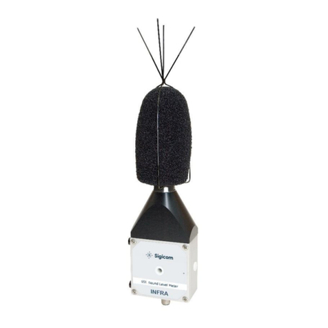
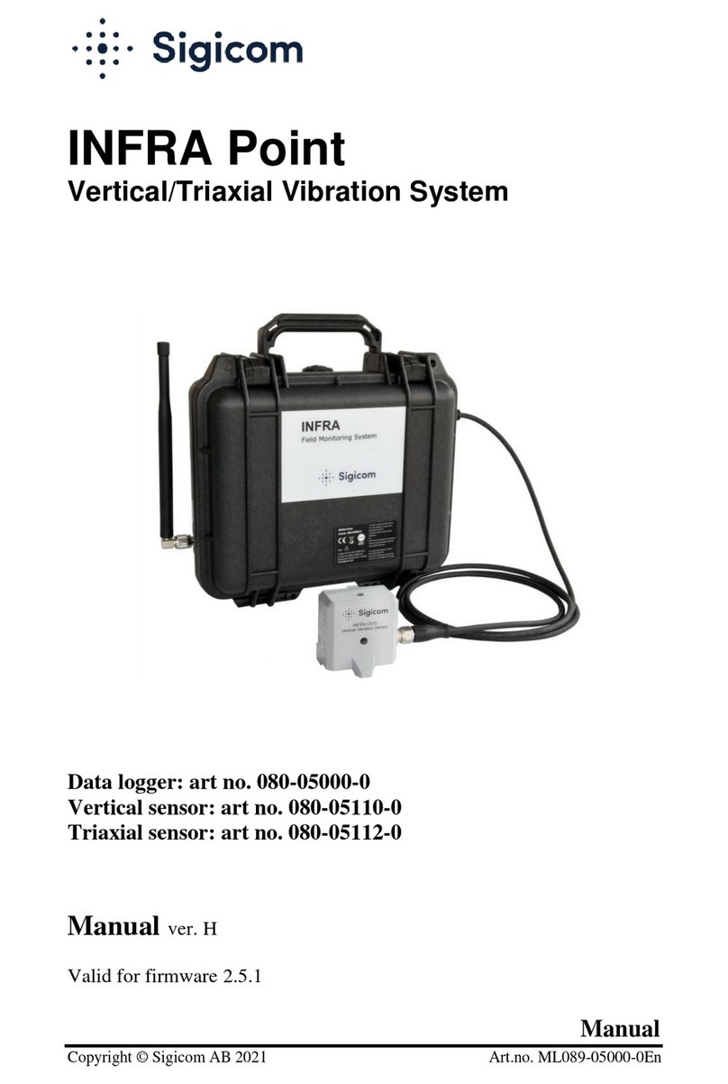
Sigicom INFRA S50 User manual

Manual
Copyright ©Sigicom AB 2003-2014 Art.no ML089B02850-0En
INFRA S50
Sound Level Meter
Art no. 080-02850-0
Manual ver. F Valid for firmware version 1.8.0


Copyright ©Sigicom AB 2003-2014
1
Developed and manufactured by:
Sigicom AB
Alfred Nobels Allé 214
SE –146 48 Tullinge, Sweden
IMPORTANT SAFETY INSTRUCTIONS –read this before use.
US customers:
This device complies with Part 15 of the FCC Rules. Operation is
subject to the following two conditions:
(1) this device may not cause harmful interference, and
(2) this device must accept any interference received, including
interference that may cause undesired operation.
Canadian customers:
This Class B digital apparatus complies with Canadian ICES-003.
Cet appareil numérique de la classe B est conforme à la norme
NMB-003 du Canada.
EU customers:
This equipment complies with directives: EMC 2004/108/EC and
LVD 2006/95/EC.
This equipment falls under the Waste Electrical and Electronic
Equipment Directive (WEEE directive) 2002/96/EC with its last
update 2009, category 9: monitoring and control instruments:
Scrapped equipment should be sent back to the manufacturer of
the equipment (Sigicom) for proper handling according to the
WEEE directive.
Sigicom’s partner for recycling of scrapped equipment is Hans
Andersson Recycling Stockholm AB, with transport certificate
no. 562-1372-2012 (Länsstyrelsen i Stockholms län).

2 Copyright ©Sigicom AB 2003-2014
Table of Contents
1 Introduction.....................................................................................4
1.1 About this manual.............................................................5
1.2 Features ............................................................................6
1.3 Unpacking and parts identification...................................7
1.4 Safety................................................................................7
2General description ....................................................................8
3Design features.........................................................................10
3.1 Acoustical quantities.......................................................10
3.2 Frequency weightings.....................................................10
3.3 Time weightings.............................................................10
3.4 Level ranges....................................................................11
3.5 Display devices...............................................................11
3.6 Interval files....................................................................12
3.7 Transient file...................................................................12
4Configuration and operation ....................................................14
4.1 Random-incidence microphone......................................14
4.2 Mounting ........................................................................15
4.3 Pressure reflection phenomena.......................................15
4.4 Parameters ......................................................................17
4.5 Measurements of low-level sounds ................................20
4.6 Quick Start......................................................................21
4.7 Periodical testing ............................................................22
5Consider this ............................................................................23
6Post-processing of data ............................................................24
7Maintenance and calibration ....................................................25
8Accessories ..............................................................................26
8.1 Specific accessories:...............................................................26
8.2 Other accessories: ..................................................................28
9Contact and support .................................................................29
Appendix A Specifications ..............................................................30
A.1 Reference conditions (factory calibration) ............................30
A.2 Accuracy ...............................................................................30
A.3 Linear operating range (sinusoidal signals)...........................31
A.4 Microphone ...........................................................................31

Copyright ©Sigicom AB 2003-2014
3
A.5 Electrical test method............................................................32
A.6 Overload handling.................................................................32
A.7 Power consumption...............................................................32
A.8 Mechanical data ....................................................................33
A.9 Approvals..............................................................................33
Appendix B Glossary.......................................................................34

4 Copyright ©Sigicom AB 2003-2014
1 Introduction
Welcome to S50, a Class 1 precision sound level meter with
integrated microphone.
The S50 Sound Level Meter is to be integrated with the INFRA Field
Monitoring System. See one example of this in the figure here
below.
Example of a setup of the INFRA Field Monitoring System
For a comprehensive description of the INFRA Monitoring System
please consult the INFRA Master manual.

Copyright ©Sigicom AB 2003-2014
5
1.1 About this manual
This manual covers the following topics:
Chapter 1 –Introduction: Overview of S50’s measurements
capabilities and some introductory information.
Chapter2 –General description: An overview of S50 and
the INFRA Field Monitoring System.
Chapter 3 –Design features: Description of standards,
parameter settings and measurement data files.
Chapter 4 –Configuration and operation: Mounting
description, and detailed description of S50’s standards and
parameter settings. It also includes a Quick start guide and
how periodical testing is performed.
Chapter 5 –Consider this: Important information about
different environmental aspects.
Chapter 6 –Post-processing of data: How data is transferred
and processed in the INFRA Field Monitoring System.
Chapter 7 –Maintenance and calibration: Information about
calibration interval etc.
Chapter 8 –Accessories: Lists the accessories for S50, and
S50-related accessories for the INFRA Field Monitoring
System.
Chapter 9 –Contact and support: Contains contact
information to Sigicom AB.

6 Copyright ©Sigicom AB 2003-2014
1.2 Features
INFRA S50 Sound Level Meter simultaneously measures both
maximum and equivalent sound pressure level. It meets the class 1
requirements of the standards:
ANSI S1.4-1983 (R2006), S1.4a-1985 (R2006)
ANSI S1.43-1997 (R2007)
IEC 61672-1:2002
INFRA S50 Sound Level Meter offers the following features:
Full integration with INFRA Field Monitoring System
which makes it possible to combine the sound level meter
with geophones (vibration) and a numerous of other sensor
types.
Interval and transient data are recorded in the Datalogger
(e.g. INFRA Master, Mini or Micro) and can be
automatically sent with for example GPRS to the database.
Possibility to connect more than one sound level meter to
each Datalogger.
Selectable time interval of the interval data.
A trigger level for recording a sound clip (transient) with up
to 10 seconds duration can optionally be set. The one
second period just before the trig (named pre-trig) is always
included in the sound clip.
Possibility (within INFRA software tools) to listen to the
sound clip, in order to identify the source of the noise.
Possibility in post processing to apply frequency analysis of
transients (e.g. third octave) up to 1250 Hz.
Simultaneous measuring in two channels: MAX or PEAK
(Lmax/Lpeak), and equivalent sound pressure level (Leq).
Frequency weighting: A or C.
Time weighting: SLOW (1s) or FAST (0.125s).
A number of level ranges.
A red LED for overload indication.

Copyright ©Sigicom AB 2003-2014
7
1.3 Unpacking and parts identification
Your S50 Sound Level Meter has been shipped in protective
packaging. Please verify the package content with the following list:
S50 Sound Level Meter, including (integrated) random-
incidence microphone, windscreen and bird spikes.
Foam (which protects your S50 from shock during
transportation).
Calibration Document.
Please, report immediately any damage or shortage to Sigicom AB.
Record the instrument’s serial number. You will be asked to give this
number in any S50 related communication you may have with
Sigicom AB.
1.4 Safety
Do never attempt to disassemble the instrument.
Do never attach your S50 Sound Level Meter to any other system or
current source than cables and units within the INFRA Field
Monitoring System.

8 Copyright ©Sigicom AB 2003-2014
2General description
The S50 Sound Level Meter is a class 1 precision sound level meter
to be integrated with INFRA Field Monitoring System. It can
simultaneously measure both maximum and equivalent sound
pressure level (Lmax and Leq, respectively).
The S50 Sound Level Meter has an integrated random-incidence
microphone for general purpose acoustic measurements, especially
suitable to use in diffuse sound fields. The microphone has a large
dynamic range and a wide frequency response.
The S50 Sound Level Meter is to be connected to the INFRA Field
Monitoring System by any of the available INFRA Sensor Cables.
The Sensor Cable supplies the S50 Sound Level Meter with both
electrical power and all necessary communication.
S50 Sound Level Meter connected with
INFRA Datalogger in a minimal configuration.

Copyright ©Sigicom AB 2003-2014
9
Within INFRA Field Monitoring System it is possible to measure a
number of other quantities simultaneously with the sound pressure
level measurements, for example:
vibration (geophone) in one direction
vibration (geophone) in three directions
air blast
dust monitoring
wind, speed and direction
air temperature
air humidity
atmospheric pressure
etc.
All quantities are synchronized, and can be viewed in any of the
INFRA presentation systems.

10 Copyright ©Sigicom AB 2003-2014
3Design features
3.1 Acoustical quantities
The S50 Sound Level Meter has a number of pre-defined
measurement standards, each including any of the pairs
Lmax and Leq
Lpeak and Leq
where
Lmax:The highest RMS reading over the selected interval time.
Lpeak:The absolute peak value over the selected interval time.
Measurement of Lpeak is normally used in the protection of
humans’ hearing against sudden large pressure peaks.
Leq:The time-averaged sound pressure level over the selected
interval time (see below). It has the formal symbol LAT (IEC
61672-1), but for mainly historical reasons LAT is commonly
referred to as Leq. It is usually called the equivalent sound level.
3.2 Frequency weightings
S50 Sound Level Meter handles both A- and C-frequency weighting
filtering. One of these frequency weightings can be selected at a
time.
3.3 Time weightings
S50 Sound Level Meter handles two time constants:
0.125 seconds for time weighting F (FAST)
1 second for time weighting S (SLOW)
One of the time weightings can be selected at a time.

Copyright ©Sigicom AB 2003-2014
11
3.4 Level ranges
S50 Sound Level Meter handles the level ranges (Lmax):
20-95 dBA
25-95 dBC
30-105 dBA/dBC
40-115 dBA/dBC
55-130 dBA/dBC
One of the level ranges can be selected at a time.
3.5 Display devices
S50 Sound Level Meter shall be connected to the INFRA Field
Monitoring System which has several capabilities of displaying the
measured signals. The resolution is 0.1 dB.

12 Copyright ©Sigicom AB 2003-2014
3.6 Interval files
Lmax/ Lpeak and Leq data are saved in separate files, named interval
files. For traceability of the registrated data, all files have an
extensive header where all necessary meta-data is saved. Attached to
each saved data there is information about overload, invalid data and
registration status changes.
3.7 Transient file
The S50 records a transient file (sound clip) after a trigger event. The
trigger event is fired when any of the following is valid:
The sound pressure level in the Lmax/Lpeak channel becomes
larger than the threshold level, and the threshold is
activated.
Another sensor connected to the same Datalogger triggers.
The operator of the Datalogger fires a manual trig.
.
Recording post-trig length is adjustable between 1 and 10 seconds.
Pre-trig is always 1 second.
Transient data:
The microphone signal is tapped from the signal chain after
the dBA or dBC filter, but before the RMS/PEAK detector
to enable post-processing.
Before the signal is saved in the transient file it is low-pass
filtered (-3dB at 1.5kHz) using a FIR filter and down-
sampled to 4096 Hz.
Limitations of possible amount of recordings:
The transient memory in the S50 has a length of 11 seconds,
and must be transferred to the Datalogger before a new
transient can be recorded.
In order to enable long cables and low power of the
communication, the transfer capabilities between S50 and
the Datalogger are rather slow. It transfers approx. 0.15 s of
S50-data per second or 0.4 s of vibration sensor data per
second.

Copyright ©Sigicom AB 2003-2014
13
All sensors connected to the same Datalogger shares the
transfer channel.
If the recording length is set short, the transient memory
will be splitted into two or more transient files. This enables
that more than one transient file may be recorded before the
memory becomes full.

14 Copyright ©Sigicom AB 2003-2014
4Configuration and operation
4.1 Random-incidence microphone
Random-incidence microphones are intended to measure sound in a
diffuse field where the sound is arriving from undefined directions,
for example in an area with many reflections or numerous sources.
The random-incidence microphone in S50 Sound Level Meter
measures the sound pressure which existed before it was placed in a
diffuse field. At higher frequencies it compensates for the effects of
reflection and diffractions because of its presence in the sound field.
The most ideal frequencies response is reached when the microphone
is pointed 90 degrees off the direction of the sound source. At
normal diffuse field measurements, the S50 shall be mounted with its
microphone pointing up-right. A little overcompensation will occur
at higher frequencies, but this is within the class 1 tolerances of the
standards. The figure below shows the microphone free field
responses for various angles of incidence and also, based on these,
random incidence. The definitions used here are described in the
standards IEC 61183 and ANSI S1.10.
Free-field frequency characteristics of the measured sound pressure level
for various angles of incidence. The calculated random incidence is also illustrated.

Copyright ©Sigicom AB 2003-2014
15
4.2 Mounting
As explained earlier in this manual, the S50 shall be mounted with
the microphone pointing upwards. The windscreen shall always be
used when measuring outdoors because it reduces possible wind
induced noise. The windscreen also offers protection against rain,
dust particles and mechanical damage.
The mounting wedge
1
shall be used when the S50 Sound Level
Meter is to be mounted to a wall, see picture below. The distance
between the wall and the center line (at the top) of the microphone is
then 15 mm.
S50 Sound Level Meter mounted with a Mounting Wedge against a wall.
4.3 Pressure reflection phenomena
With the S50 mounted on a wall, it implies that the sound pressure
reflects against the wall, which then is very close to the microphone.
This short distance implies that the measured sound pressure level
(of the lower frequencies) will be 6dB higher compared to a situation
1
See section 8 Accessories.

16 Copyright ©Sigicom AB 2003-2014
where the S50 is mounted far away from any object. However, the
higher frequencies of the sound pressure level are damped, because
their wavelength will be in the same magnitude as the distance
between the microphone and the wall. The figure below shows the
measured sound pressure level of sinusoidal sound waves
propagating perpendicular towards a wall (with perfect reflection) as
function of the frequency levels for the distances 6, 15 and 17 mm
between the center of the microphone and the wall. The illustrated
pressure level is relative to what should have been measured without
any reflections. Note that a maximal distance of 15 mm is a
requirement for wall mounted microphones in many regulations, and
this is the distance when S50 Sound Level Meter is mounted using
the Mounting Wedge, see the previous section. Compensation for the
6 dB increased measurement is not done in the S50, but can be setup
in the post-processing.
Measured sound pressure level as function of the frequency because of total
reflections for three distances between the center of the microphone and the wall
(sinusoidal sound wave).

Copyright ©Sigicom AB 2003-2014
17
4.4 Parameters
4.4.1 Standard selection
There are totally 18 selectable standards, which is the same as
combinations of the parameters:
acoustic quantity
time weighting
level range
frequency weighting
Standard
Acoustic
quantities
Time
weighting
Level range and
Frequency weighting
S01
Lmax and Leq
FAST
20 - 95 dBA
S02
Lmax and Leq
FAST
30 –105 dBA
S03
Lmax and Leq
FAST
40 - 115 dBA
S04
Lmax and Leq
FAST
55 - 130 dBA
S05
Lmax and Leq
FAST
25 - 95 dBC
S06
Lmax and Leq
FAST
30 - 105 dBC
S07
Lmax and Leq
FAST
40 - 115 dBC
S08
Lmax and Leq
FAST
55 - 130 dBC
S09
Lpeak and Leq
PEAK
55 - 130 dBA
S10
Lpeak and Leq
PEAK
55 - 130 dBC
S11
Lmax and Leq
SLOW
20 - 95 dBA
S12
Lmax and Leq
SLOW
30 - 105 dBA
S13
Lmax and Leq
SLOW
40 - 115 dBA
S14
Lmax and Leq
SLOW
55 - 130 dBA
S15
Lmax and Leq
SLOW
25 - 95 dBC
S16
Lmax and Leq
SLOW
30 - 105 dBC
S17
Lmax and Leq
SLOW
40 - 115 dBC
S18
Lmax and Leq
SLOW
55 - 130 dBC

18 Copyright ©Sigicom AB 2003-2014
Note that each standard has its own settings of the parameters:
Interval time, Upper thresholds, Record (transient) time and
Customer string. When another standard is selected, these parameters
need to be reviewed.
Select range according to the expected sound pressure levels. It is
preferred to analyze the measurements shortly after installation to
verify that proper range and threshold is set.
4.4.2 Interval time
The interval time is how often the measured value of each channel is
saved to an interval file. The interval time can be selected to one of:
1
2
, 2, 4, 5, 6, 10, 15, 20, 30 seconds
1, 2, 4, 5, 6, 10, 15, 20, 30, 60
3
minutes
4.4.3 Upper threshold on the Lmax / Lpeak channel
If the sound pressure level of the Lmax / Lpeak channel
becomes larger than its upper threshold level, the the Lmax /
Lpeak signal is recorded in a transient file.
The INFRA functionalities SMS and Server messages can
be activated such that each time the sound pressure level in
the Lmax / Lpeak channel becomes larger than the upper
threshold level, a message will be sent to one or several
recipients.
The upper threshold can be set to OFF which means that it
has no effect on the system.
When upper threshold is set to OFF, other sensors on the
same Datalogger can still trigger a transient file recording.
4.4.4 Upper threshold on the Leq channel
4
If the interval value of the Leq channel becomes larger than
its upper threshold level, new interval files are created and
uploaded to the data server.
2
1, 2 and 4 seconds are available if firmware version is 1.6.0 or newer.
3
60 minutes is available if firmware version is 1.8.0 or newer.
4
Upper threshold on the Leq channel is available if firmware version is 1.7.0 or newer.
This manual suits for next models
1
Table of contents
Other Sigicom Measuring Instrument manuals
