1U619-001 COMM / NAV / DME / ATC CONTROL PANEL
Pub. No. 86M066
Page 2 Issue C
1.0 GENERAL INFORMATION
1.1 INTRODUCTION
This manual contains operation and installation information for the 1U619-001COMM / NAV /
DME ATC Control Panel manufactured by Sigma Tek, Inc., 1001 Industrial Road, Augusta,
Kansas 67010. The 1U619-001 Control Panel is designed specifically to replace older
mechanical Control Panels installed in various 500 series Citation Jets manufactured by Cessna
Aircraft Company.
1.2 DESCRIPTION OF EQUIPMENT
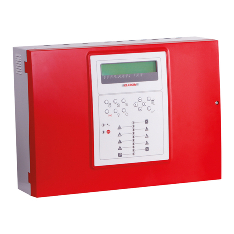
The 1U619-001 Control Panel is designed to provide remote tuning of two VHF COMM
Transceivers, two VHF NAV / DME Receivers and one or two Air Traffic Control Transponders.
The Control Panel is capable of tuning within a VHF COMM frequency range of 118.00(0) to
136.990 MHz in 25 KHz or 8.33 KHz increments (switch selectable). An optional extended
tuning range from 137.00(0) to 151.97(5) MHz in 25 KHz increments is available. The VHF
NAV frequency range is 108.00 to 117.95 MHz in 50 KHz increments. The capability of pre-
selecting frequencies for both the NAV and COMM provide a single level of memory. Up to
Ten (10) additional memory channels can be stored and retrieved with the “MEM” buttons on the
Control Panel. Audio Volume controls with integrated power Off switch are available for both
COMM and NAV radios. Other ancillary functions incorporated on the Control Panel are;
Squelch On/Off, Comm Test, Marker Sensitivity Hi/Lo, Nav Test, Transponder Ident, Test,
Normal/Standby/Lo, Altitude Reporting On/Off and Transponder 1 or 2 select.
Note: A small toggle switch Guard Plate is attached to all 1U619-001 units before
shipping. In installations that utilize only one (1) Transponder Radio, this Guard
Plate should remain attached to the Control Panel. Those installations that
contain two (2) Transponder Radios require the removal of this Guard Plate. This
will allow the selection of either Transponder 1 or 2.
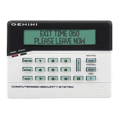
The Control Panel has five (5) dual line, five and a half (5½) digit, Liquid Crystal Display
modules. The displays offer a high degree of readability in bright sunlight, and are backlit for
low ambient light viewing. The Transponder display is “masked” to show only the top display
line.
The Comm & Nav displays are divided into two (2) lines. The top line is referred to as the
"Active" display (or frequency), while the bottom line is referred to as the "Pre-Select" display.
Frequency updating is performed by tuning the knobs associated with the display above it. All
updates target the bottom display line. The Pre-selected frequency is activated by pressing the
Transfer (TFR) switch on the tuning knob stack.
The 1U619-001has an integrally lighted plastic panel which includes all pertinent nomenclature
required to identify the function of each control. Dimming is controlled by the aircraft 5 volt DC
dimming buss accessed through the rear connector. The nomenclature is clearly visible in both
low and high ambient light conditions.
Internal circuitry of the Control Panel is comprised of five (5) independent Modules, one for each
radio. Each Module is similar in construction, containing three (3) electronic printed circuit
board (PCB) assemblies and a back plane circuit board. One electronic PCB assembly, which is
duplicated in all five Modules, is the micro controller (MCU) board. This board controls the
