2524
Instructions for installation, operation and maintenance
instruction manual for use translated from Italian
Lifting accessory
Kera lift 1A4 /1A5 / 1D2
INDEX
0.0. INTRODUCTION.
1. 0. ESSENTIAL SAFETY AND HEALTH REQUIREMENTS.
1.1. INTEGRATION OF SECURITY.
1.2. INFORMATION AND SAFETY OF MACHINE LIFTING MACHINE.
1.2.1. USE OF MACHINE LIFTING MACHINE.
1.2.2. INDICATIONS AND CONTRAINDICATIONS.
1.3 MAIN PLANTS FOR THE PLATE
LIFTING MACHINE.
1.3.1 MATERIALS COMPONENT THE MACHINE
1,3,2 DISPOSAL
1.4. SAFETY REQUIREMENTS.
1.4.1. INSTALLATION.
1.4.2. MACHINE TRANSPORT AND DISABLING.
ACCESSORIES.
1.4.3.1 ASSEMBLING COMPONENTS
1.4.4. POSITIONING.
2.0. MACHINE SAFETY SYSTEMS FOR PLASTER LIFTING.
2.1. IDENTIFICATION TARGETS.
3.0. TECHNICAL DATA.
4.0. HOW TO PREPARE FOR WORK.
4.1. HANDLING PRECAUTIONS.
6.0. MAINTENANCE.
7.0. DIAGNOSTICS.
7.1 ASSISTANCE.
7.1.1 MANUAL UPDATE
7.2 MANUFACTURING PROCESS.
7.3 COLLABORATION WITH USER
8.2. TABLES PARTS OF REPLACEMENT.
WARRANTY CERTIFICATE.
0.1. EC DECLARATION OF CONFORMITY.
0.0. INTRODUCTION.
This instruction manual is addressed to the user of the machine and con-
tains all the information regarding the installation, use and maintenance,
accompanied by all the necessary safety information.
The instruction manual must be kept close to the machine, protected from
dirt and moisture, always available for any reference.
This machine should only be used for the purpose for which it was
expressly designed.
Any other use is considered improper and therefore dangerous. The
manufacturer can not be held responsible for any damage resulting
from improper use or as a result of non-compliance with the safety and
operating rules stated in this instruction manual.
- Within this instruction manual, the highlighted character serves to
highlight an important warning to be given special attention.
- A sticker is attached to the machine with:
- The EC symbol attesting the conformity of the machine with the appli-
cable Community legislation at the time of construction of the machine.
- The circular symbols of obligation, serve to signal the obligation of the
use of protective systems such as gloves trousers shoes and glasses.
- The circular symbol with a book, indicates the presence of the instruction
manual and therefore requires reading before installing or using the
machine.
- The rectangular symbol with the maximum flow rate indicated.
1. 0. ESSENTIAL SAFETY AND HEALTH REQUIREMENTS.
1.1. INTEGRATION OF SECURITY.
The machine is designed to be capable of being operated, operated,
adjusted, and maintained if carried out under the intended conditions,
without the risk of exposing persons to such persons, while also
taking into account the reasonably foreseeable misuse.
The measures taken are intended to eliminate any risk during the fo-
reseeable existence of the machine, including the stages of transport,
assembly, dismantling, dismantling (dismantling) and scrapping.
The machine is designed and constructed taking into account the
limitations imposed on the operator by the necessary or predictable
use of personal protective equipment.
The machine is supplied with all the essential equipment and acces-
sories to be able to adjust, maintain, and use it in safe conditions.
1.2. INFORMATION AND SAFETY OF MACHINE LIFTING MACHINE.
Read this manual carefully before installing the machine and store it
for future reference.
1.2.1. USE OF MACHINE LIFTING MACHINE.
The machine can be used for lifting and handling large size tiles.
1.2.2. INDICATIONS AND CONTRAINDICATIONS.
Only the machine must be enabled:
1 in number to limit the effort to 25kg for men and 20kg for women.
2 pupils with adequate education to fully understand the information
contained in this manual (minimum recommended: lower school
license)
3 employees who have received instruction on using the machine
from responsible and experienced personnel.
4 It is forbidden to lift the machine with systems such as winches,
pulleys, other than operator hands.
5 It is forbidden to lift the machine and its load at greater heights than
1.1 meters from the ground
6 the use of glasses, safety shoes, gloves and long pants is compul-
sory.
7 Block all the knobs before lifting the tile.
8 Before lifting a new material, it is necessary to test the suction
cup take-up time, engaging a tile and keeping it 5 cm high. from
the ground for a triple time, compared to the one then needed for
handling.
This is because, if the vacuum holding time is hours, on a smooth
material with new suction cups, this can be reduced to a few seconds
on very rugged tiles or by using old or worn rubber suction cups.
10 This machine can not be used for lifting porous materials
11 The machine can not be used in ways other than those for which
it was designed.
12 Do not lift any material whose weight and dimensions are not
proportional to the structure of the machine.
13 Do not raise with room temperature or materials below 5 ° or
greater than 50 °. It is also good that the material and suction cups
are clean and dry.
14 Any modification that alters the characteristics of the machine
must only be carried out by the manufacturer that will attest confor-
mity. Therefore any modification or maintenance work not covered in
this manual is considered arbitrary.
15 The flow rate is guaranteed at a maximum altitude of 1000 m. on
the sea level16 Do not place suction cups on surfaces that are wet
with chemicals other than water.
17 To clean the suction cups, use only water and kitchen soap.
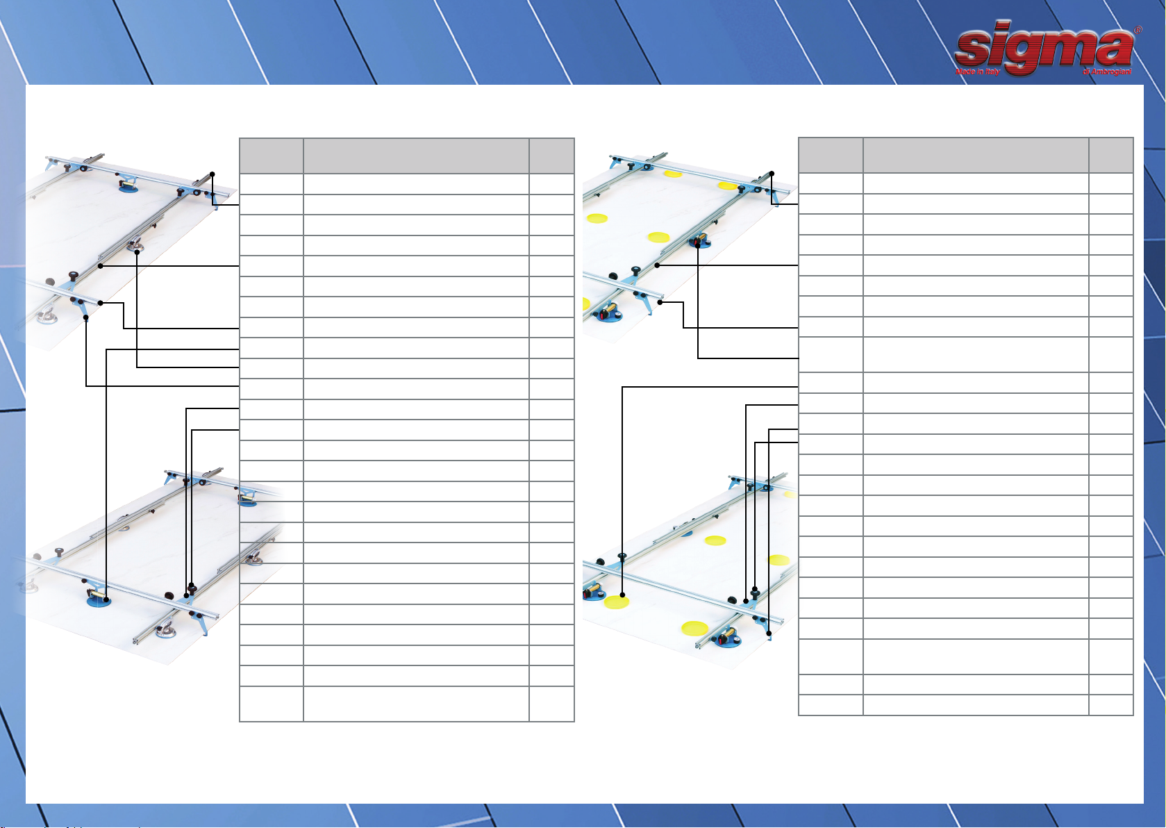
1.3. MAIN PARTS OF PLATE CUTTING MACHINE.
The machine consists of the following main parts:
Longitudinal and / or transverse extrusions
Suction Cups
Safe Anti Fall
-) - Further details are identifiable in the enclosed explosions.
1.3.1. MATERIALS THAT MAKE UP THE MACHINE:
Steel Ac
Aluminum Al
Rubber tire SBR
Nylon PA
5.0. DISPOSAL
When dismantling the machine, allocate each component to the corre-
sponding recycle to
avoid environmental pollution.
End-of-life cards are available on our website: www.sigmaitalia.com
1.4 SAFETY REQUIREMENTS.
1.4.1. INSTALLATION.
1.4.2. MACHINE TRANSPORT AND DISABLING.
The machine can get packed inside a cardboard box.
Check the integrity of the packaging by making sure that no obvious
damage has occurred
during transport and remove the machine from the packaging.
WARNING: Remove the packaging elements that may be a source of
danger.
1.4.3. ACCESSORIES.
Check for all accessories inside the machine:
Instruction manual + various anti falls.
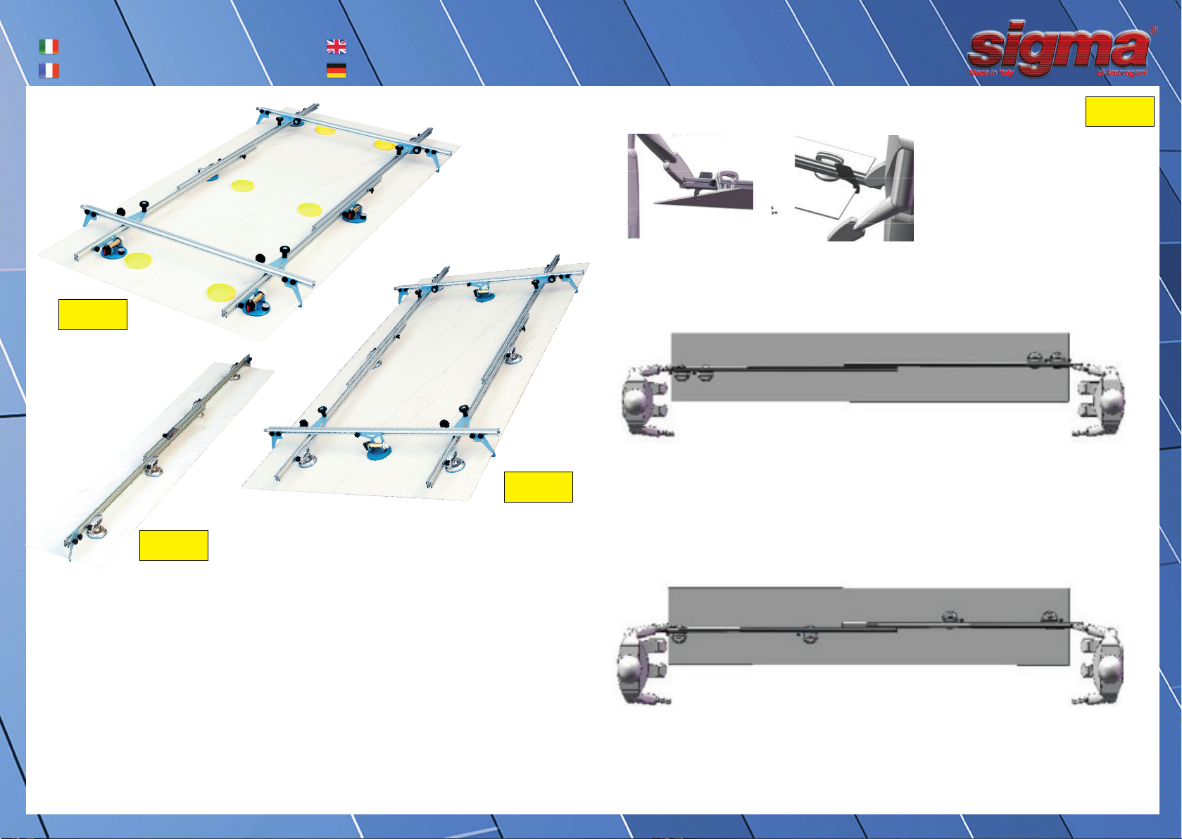
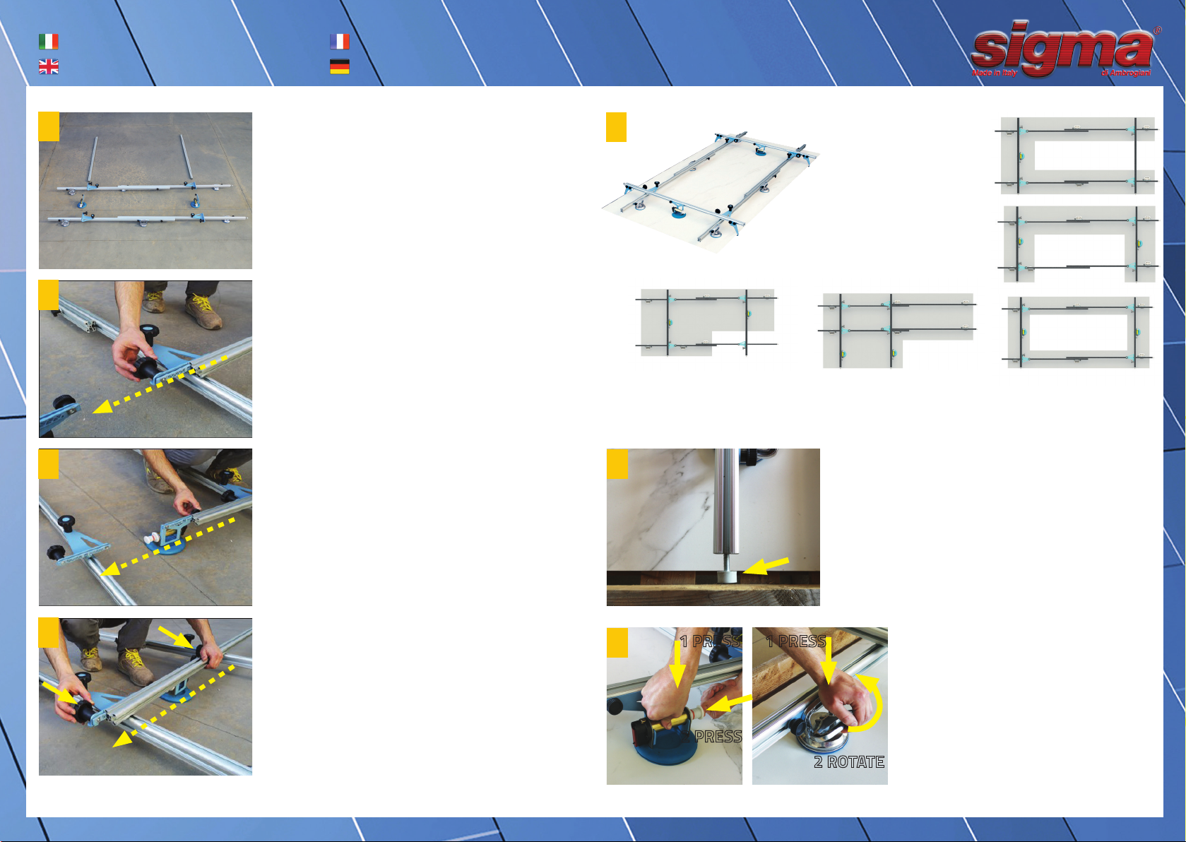
1.4.3.1 ASSEMBLING COMPONENTS
To facilitate transportation, the machine may have been partially disas-
sembled, follow the pictures as mounting instructions.
1.4.4. POSITIONING.
Identify a sufficiently wide planar area, with a solid, solid, flat surface.
Preferably sheltered from rain or snow.
Remove the work area from objects that can be a source of danger and
stumbling.
Always make sure that the plane on which the machine is placed is of
sufficient capacity to the weight to support and that it will provide the
necessary stability.
Keep clean and properly illuminate the work area.
2.0. MACHINE SAFETY SYSTEMS FOR PLASTER LIFTING.
The machine is equipped with the following mechanical protection
devices:
There are several anti-fall safety devices available to both low extruded
and high extruded.
It is advisable to mount them on the long sides of the tile.
The retaining tooth must fully engage the edge of the tile.
2.1. IDENTIFICATION TARGETS
The machine identification plates are:
1 ° Fixing plate with the following information: A + B + C + D + E + F
2 ° Plaque plate on the fixing plate containing the identification informa-
tion of the manufacturer.
A) Model of the machine
B) Max lifting weight
C) Accessory weight
D) Year of construction
E) CE marking
F) Obligatory pictograms
: Whenever the manufacturer is questioned, it is indispensable to indicate
the model of the machine specified on the 1st identification plate.