Noblelift ACX 10E User manual

Version 06/2013
ACX-SMS-001
WARNING
Do not use the truck before reading and
understanding these operating instructions.
NOTE:
•Please check the designation of your present
type at the last page of this document as well
as on the ID-plate.
•Keep for future reference.
OPERATING INSTRUCTION HANDBOOK
MANUAL SCISSOR LIFT PALLET TRUCK/
ELECTRICAL SCISSOR LIFT PALLET TRUCK WITH ELECTRIC
LIFTING

1

2
FOREWORD
Before operating the scissor lift pallet truck, read this ORIGINAL INSTRUCTION HANDBOOK carefully and
understand the usage of the truck completely. Improper operation could create danger.
This handbook describes the usage of a scissor lift pallet truck with manual or electric lifting function. When
operating and servicing the truck, make sure, that it applies to your type.
Chapter 11 describes specialized stipulations and regulations for the American market.
Follow these instructions and stipulations if you operate the truck within the American
market!
Keep this handbook for future reference. If this or the warning/ caution labels are damaged or got lost,
please contact your local dealer for replacement.
This truck complies, if applicable, with the requirements according to EN 3691-5 (Industrial trucks- safety
requirements and verification, part 5), EN 12895 (Industrial trucks- electromagnetic compatibility, only
electric lift version), EN 12053 (Safety of industrial trucks- test methods for measuring noise emissions, only
electric lift version), EN 1175 (Industrial truck safety – electrical requirements, only electrical lift version),
assumed the truck is used according to the described purpose.
ATTENTION:
•Environmentally hazardous waste, such as batteries, oil and electronics, will have a negative effect on
the environment, or health, if handled incorrectly.
•The waste packages should be sorted and put into solid dustbins according to the materials and be
collected disposal by local special environment protection bureau. To avoid pollution, it’s forbidden to
throw away the wastes randomly.
•To avoid leaking during the use of the products, the user should prepare some absorbable materials
(scraps of wooden or dry duster cloth) to absorb the leaking oil in time. To avoid second pollution to the
environment, the used absorbable materials should be handed in to special departments in terms of
local authorities.
•Our products are subject to ongoing developments. Because this handbook is only for the purpose of
operating /servicing the pallet truck, therefore please have understanding, that there is no guarantee
out of particular features out of this handbook.
NOTE: On this manual, the left sign means warning and danger, which can lead to death or
serious injury if not followed.
Copyright
The copyright remains with the company, mentioned on the CE- certificate at the end of this document or, if
sold within the USA, with the company, mentioned on the company sticker.

3

4
TABLE OF CONTENTS
1. CORRECT APPLICATION.......................................................................................6
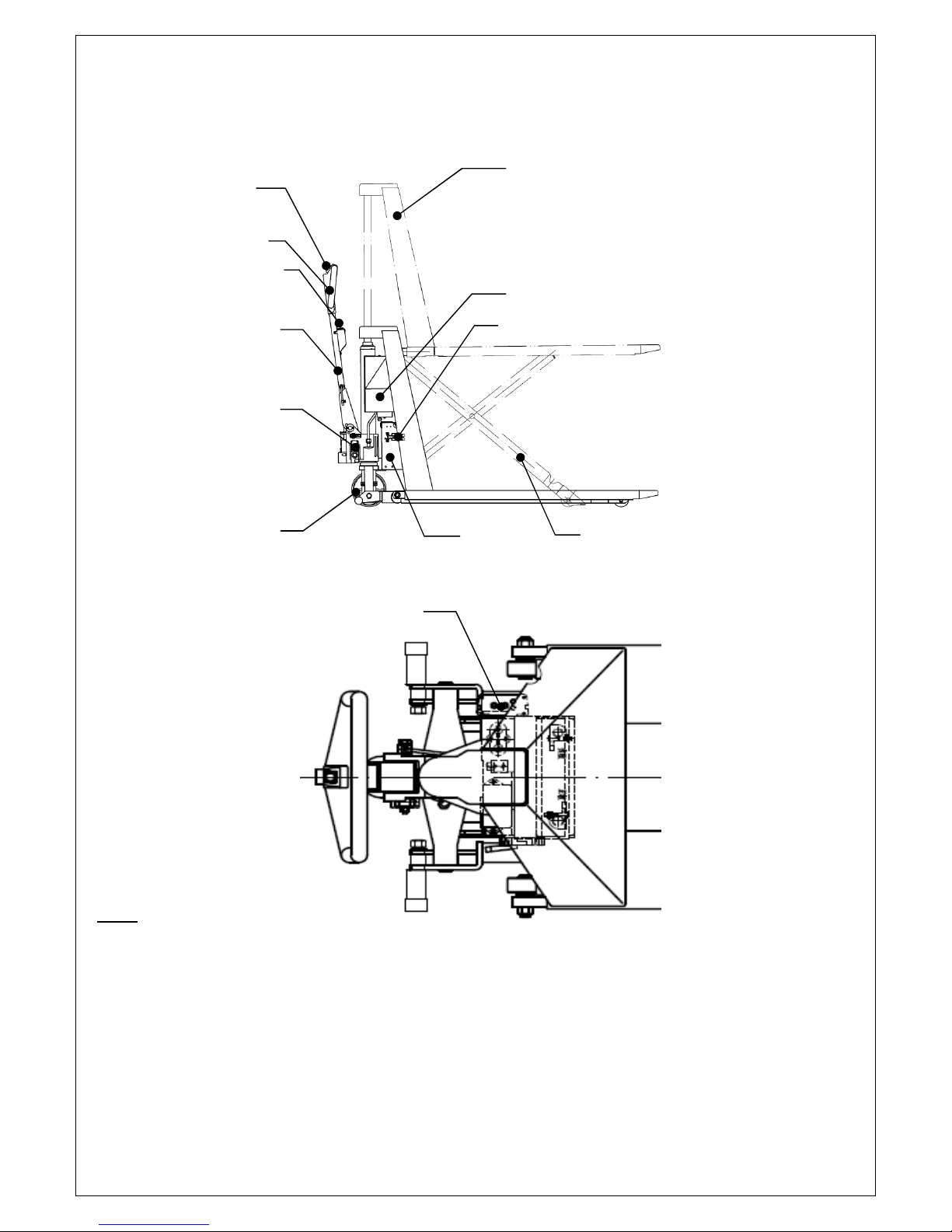
2. DESCRIPTION OF THE SCISSOR LIFT PALLET TRUCK......................................7
a. Main components ............................................................................................7
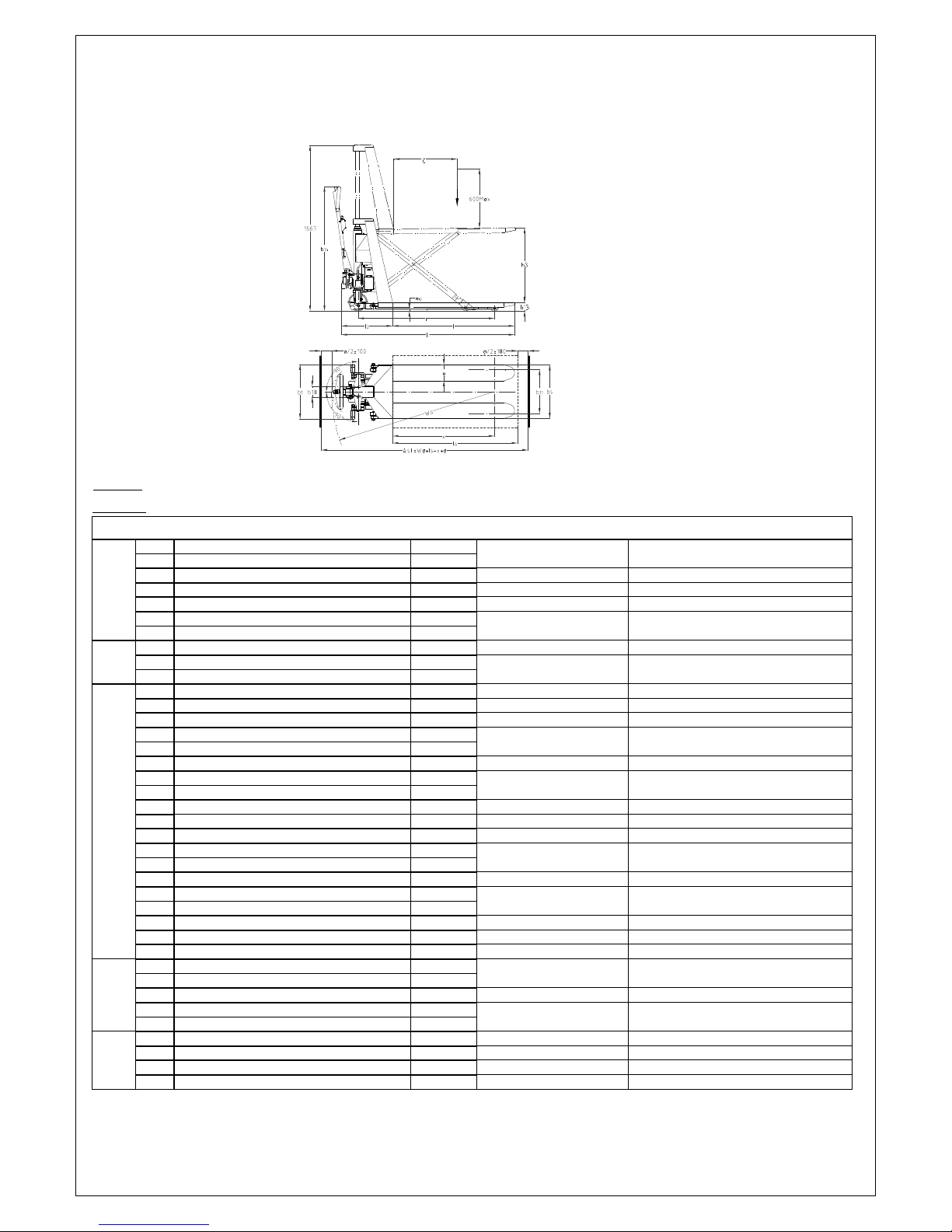
b. Main technical data..........................................................................................8
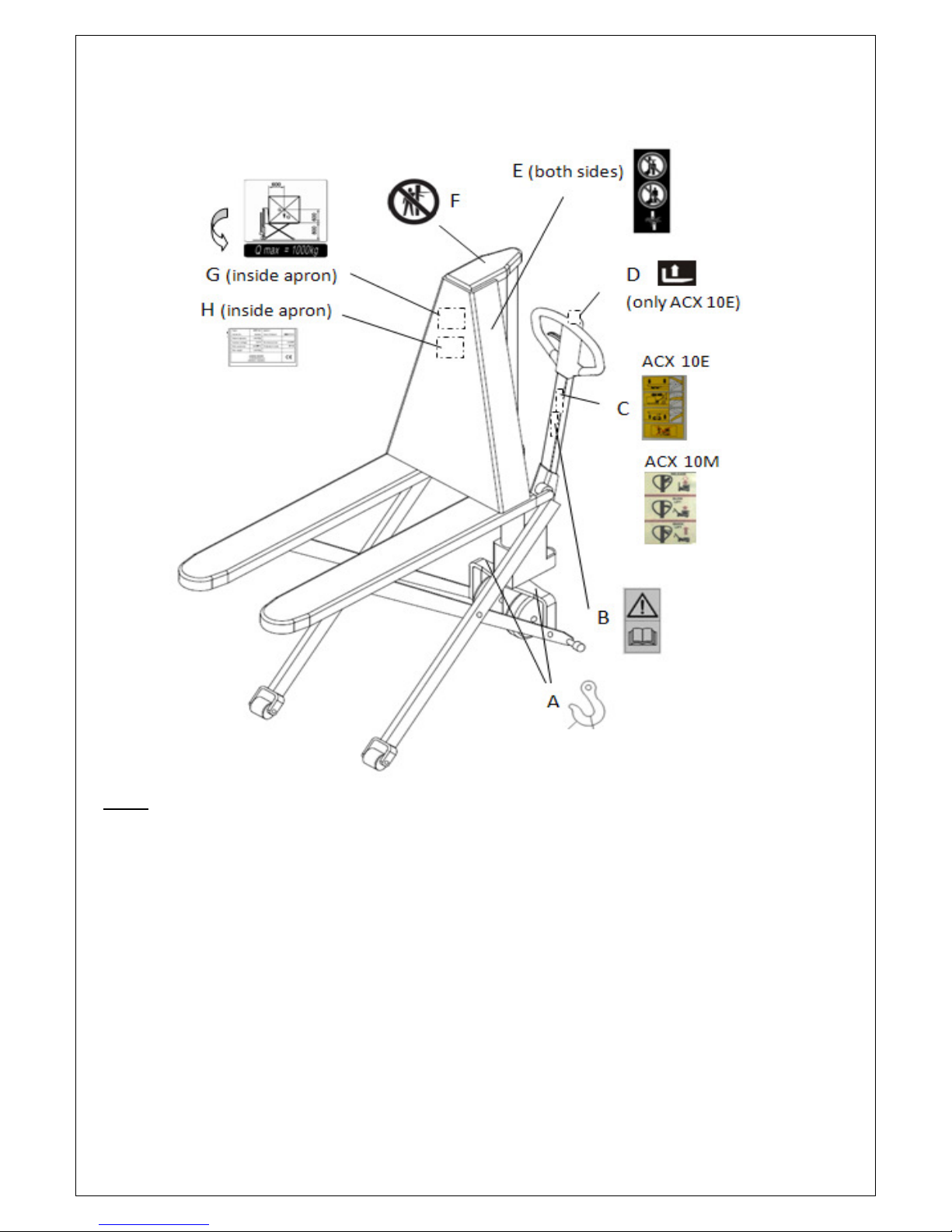
c. Description of the safety devices and warning labels ......................................9
d. Identification plate..........................................................................................10
3. WARNINGS AND SAFETY INSTRUCTIONS ........................................................10
4. COMMISSIONING, TRANSPORTING, STORAGE/ REASSEMBLING..................11
a. Commissioning – Tiller assembling ...............................................................11
b. Hydraulic valve adjustment............................................................................12
c. Lifting/transporting .........................................................................................13
d. Storage/ Reassembling .................................................................................13
5. DAILY INSPECTION..............................................................................................13
6. OPERATING INSTRUCTIONS..............................................................................14
a. Parking..........................................................................................................14
b. Lifting.............................................................................................................14
c. Lowering .......................................................................................................14
d. Moving...........................................................................................................14
e. Quick Lift (ACX 10M) ......................................................................................15
f. Malfunctions....................................................................................................15
7. BATTERY CHARGING AND REPLACEMENT (ACX 10E) ....................................15
a. Replacement .................................................................................................15
b. Battery indicator.............................................................................................16
d. Charging with Onboard charger (only ACX 10E, optional).............................16
e. Charging with external charger (only ACX 10E, optional)..............................17
8. REGULAR MAINTENANCE ..................................................................................17
9. TROUBLE SHOOTING..........................................................................................19
10. HYDRAULIC FLOW DIAGRAM AND CIRCUIT DIAGRAM..................................21
a. Hydraulic flow diagram ..................................................................................21
b. Circuit diagram (ACX 10E) ............................................................................21
11. SPECIALIZED STIPULATIONS FOR THE US- AMERICAN MARKET................22
a. Foreword/ Compliance..................................................................................22
b. Description warning labels (only US-market).................................................23
12. DECLARATION OF CONFORMITY (valid, if sold within the EU) ........................26

5

6
1. CORRECT APPLICATION
It is only allowed to use this scissor lift pallet truck according to this instruction handbook.
This truck is a manually operated scissor lift pallet truck with manual or electric lifting function designed for
transporting of palletized loads, or to be used stationary as a working platform on level ground. It is not suitable for
use in potentially explosive locations and hostile environments. Do not lift or carry person and don’t use this truck
for other purpose than its intended use. A wrong usage can cause human injuries or can damage equipment.
The “operator” or “user” is in the meaning of this instruction handbook is a natural or legal person who uses the
truck himself or on behalf it is used. The operator or user must ensure that the truck is used in the design limits. All
danger to life or danger to the user, operator or to third parties must be avoided. The operator/ the operating
company has to ensure the correct usage and has to ensure, that this truck is used only by staff, which is trained
and authorized to use this truck.
The truck has to be used on substantially firm, smooth, level and prepared surfaces.
Driving with the load on slopes is not allowed. The load must be placed approximately on the
longitudinal centre plane of the truck and must be in satisfactory condition.
The capacity is marked on the identification plate and depending on the version eventually additionally on the
capacity sticker. The operator has to consider the warnings and safety instructions.
The scissor lift pallet truck is intended to be used for indoor applications with ambient temperatures between +1°C
and + 40°C. Operating lighting must be minimum 50 Lux.
Modification
No modifications or alterations to this scissor lift pallet truck which may affect, for example, capacity, stability or
safety requirements of the truck, shall be made without the prior written approval of the original truck
manufacturer, its authorized representative, or a successor thereof. This includes changes affecting, for example
braking, steering, visibility and the addition of removable attachments. When the manufacturer or its successor
approve a modification or alteration, they shall also make and approve appropriate changes to capacity plate,
decals, tags and operation and maintenance handbooks. By not observing these instructions, the warranty
becomes void.

7
2. DESCRIPTION OF THE SCISSOR LIFT PALLET TRUCK
a.
Main components
1 Chassis
2 Tiller arm
3 Hydraulic cylinder and manual pump
4 Steering wheel
5 Scissors
6 Control lever
(7) Lifting button
(8) Key switch
(9) Hydraulic power pack
(10) Emergency plug
(11) Battery (inside)
(12) Onboard charger (optional)
Fig.1: Overview
1
(9)
(10)
5
(11)
(7)
6
2
3
(8)
4
(12)

b.
Main technical data
Q
Fig. 2: Technical data
Table 1: Main Technical data for standard version/ other version on request
Technical data sheet for industrial trucks acc. to VDI 2198
Distinguishing
mark
1.2
Manufacture
r`s type designation
ACX 10E
ACX 10M
1.3
Drive
electric
manual
1.4
Operator type
hand
hand
1.5
Load Capacity / rated load
Q(t)
1.0
1.0
1.6
Load centre distance
c(mm)
600
600
1.8
Load distance ,centre of drive axle to fork
x(mm)
978
978
1.9
W
heelbase
Y(mm)
1310
1310
Wei
ght
2.1
Service weight incl. battery(see line 6.5)
kg
152
122
2.2
Axle loading, laden front/rear
kg
767 / 371
760 / 348
2.3
Axle loading, unladen front/rear
kg
35 / 117
33 / 89
Tyres, chassis
3.1
Tyres
PU
Pu
3.2
Tyre si
ze, front
mm
∅
180×50
∅
180×50
3.3
Tyre size, rear
mm
∅
75× 50
∅
75× 50
3.4
Additional wheels(dimensions)
mm
—
—
3.5
Wheels, number front/rear(x=driven
2/ 2
2/ 2
3.6
Tread, front
b10 (mm)
155
155
3.7
Tread, rear
b11 (mm)
440
440
Dimensions
4.4
Lift (standard mast)
h3 (mm)
715
715
4.5
Height, mast extended
h4 (mm)
1660
1660
4.9
Height of tiller in drive position min/max
h14(mm)
1254
1240
4.15
Height, lowered
h13 (mm)
85
85
4.19
Overall length
l1 (mm)
1715
1725
4.20
Length to face
of forks
l2 (mm)
492
492
4.21
Overall width
b1 (mm)
575/ 695
575/ 695
4.22
Fork dimensions
s/e/l
45/160/1170
45/160/1170
4.25
Distance between fork
-
arms
b5 (mm)
540/ 685
540/ 685
4.32
Ground clearance, centre of wheelbase
m2 (mm)
18
18
4.34
Aisle width for pallets 800X1200
Ast (mm)
1986
1986
4.35
Turning radius
Wa (mm)
1564
1564
Performa
nce data
5.2
Lift speed, laden/ unladen
m/s
21/45
—
5.3
Lowering speed, laden/ unladen
m/s
53/63
81/61
Electric
-
engine
6.2
Lift motor rating at S3 15%
kW
0.
58
—
6.3
Battery acc. to DIN 43531/ 35/ 36 A, B, C,
No, maintenance
-
free
—
6.4
Battery voltage, nominal capacity K5
V/Ah
12V/5
2
Ah
—
6.5
Battery weight
kg
24
—
Note: black value is our lift pallet trucks’ value
8

9
c.
Description of the safety devices and warning labels
A Crane hook label
B Sticker to read and follow these instructions
C Operating instruction sticker
D Lifting sign (only ACX 10E)
E Warning decal: Do not step under or on the forks
F Never reach through
G Load diagram
H Identification plate
The safety and warning labels should be placed according to figure 3. The advices on the truck are additional to
this handbook. Please follow the operating instructions. If the decals are damaged or missing, please replace
them.
Fig.3: Safety and warning labels

10
d.
Identification plate
1 Type
2 Serial number
3 Rated capacity
4 System voltage
5 Net weight with/without battery
6 Name and address of the manufacturer
7 Battery mass min/max
8 Nominal power
9 Load center distance
10 Manufacturing date
11 Option, Wheel combination, fork length,
width over the fork
12 Net weight
3. WARNINGS AND SAFETY INSTRUCTIONS
DO NOT
•Allow other person then the operator to stand in front of or behind the truck when it is
moving or lifting/lowering.
•Overload the truck.
•Put foot in front of rolling wheel, Injury could result.
•Use the truck on a slope or inclined surface, the truck may become uncontrollable and
create danger.
•Lift or carry people. People could fall down and suffer severe injury.
•Use truck with unstable, unbalanced loosely stacked load.
•Use the truck in explosive atmospheres.
•Pay attention for wind forces. Wind forces might have an influence to the stability or light
weights might fall down. Don’t use the truck if you can’t ensure the stability of the truck.
Watch difference in floor levels when moving the truck. Load could fall down or the truck could get
uncontrollable. Keep watching the condition of load. Stop operating table if load becomes unstable.
1
2
3
12
6
If sold to the EU, here the
place of the CE marking
11
10
9
1
2
3
4
5
6
7
8
9
10
11
If sold to the EU, here the
place of the CE marking
Fig. 4: ID-Plate (electrical, manual)

11
Fig. 6: Axle assembling
Practice maintenance work according to regular Inspection. This truck is not designed to be water resistant,
therefore use it in dry atmospheres.
4. COMMISSIONING, TRANSPORTING, STORAGE/
REASSEMBLING
a.
Commissioning – Tiller assembling
After receiving our new scissor lift pallet truck you may
have to do following before firstly operating the truck:
•Check if are all parts included and not damaged
•Do the work according to the daily inspections as well
as functional checks.
•Eventually assemble the truck according to following
instructions.
The commissioning weight is approximately 10kg / four-
pack higher than the product weight.
Before assembling, please make sure, that the following supplied parts are included and not damaged:
•1 pc axle with hole (4)
•2 pc dowel pin (5) [one is already assembled with
the axle]
•1 pc pre- assembled tiller arm (1)
•1 pc pre- assembled chassis with pump unit (6)
•Connect the plug(optional for electric model)(Fig.
1, pos. 10)
Note: The marked number on the tiller arm
package and the chassis should be the same.
When attaching the handle, you had better squat
just in front of the pallet truck.
a) Insert the tiller arm(1) into the pump piston, then
use a hammer to insert the axle with hole into the
hydraulic pump and tiller arm from the right to the left
(Fig. 6 ).
b) Set the control lever of the handle to the
‘LOWER’ position, then pass the adjusting nut, adjusting bolt
through the hole of the axle with your hand (Fig. 7).
c) Press the tiller arm down; take away the pin
(2, Fig. 5).
d) Set the control lever of the handle to ‘QUICK LIFT’ (LIFT)
position, then raise the lever plate with the pin (2, Fig. 5) and
insert the adjusting bolt into the front slot of lever plate. Note:
Keep the adjusting nut under the lever plate.
Fig.5 Tiller assembling(symbolic)
(1 Tiller arm / 2 Pin / 3 Nut / 4 Axle with hole /
5 Dowel pin / 6 Chassis with pump unit)
Fig. 7: Side view(symbolic)

12
Lower
neutral
lift
e)Use a hammer to insert the 2
nd
dowel pin (5, Fig. 5) into the 2
nd
hole of the axle.
The draw-bar is now assembled to the pump.
For the ACX 10E connect the control cable. Fix the cable at the pump side in a way that the cable holder
can be turned. Fix the cable before the plug with the pre assembled cable strip.
b.
Hydraulic valve adjustment
On the tiller of your pallet truck, you will find the control lever, which can be regulated in three positions:
a) Lever (ACX10M)
Lower :handle up, the lever moves back to the neutral
when released
Slow lift : handle in center position
Quick lift : handle down
If necessary, you can adjust the lever according to following steps (Fig. 8):
•If the forks do not elevate while the control handle is in the Slow Lift position or Quick Lift position, turn
the adjusting nut on the adjusting bolt counter-clockwise until the Slow Lift position and the Quick Lift
position work properly.
•If the forks do not lower down while the control handle is in the Lower position, turn the adjusting nut
clockwise until the Lower position works properly.
•If the forks do not lift slowly when the control handle is in the Slow Lift position, turn the adjusting nut
clockwise until the Slow Lift position works properly.
•If the forks do not lift quickly while the control handle is in the Quick Lift
position, turn the adjusting nut counter- clockwise until the Quick Lift position
works properly.
b) Lever(ACX10E)
Lower : handle up, the lever moves back to the neutral
Neutral : handle in center position
Lift : handle down
If necessary, you can adjust the lever according to following steps (Fig. 9):
•If the forks elevate while pumping in the Neutral position, turn the adjusting nut on the adjusting bolt
clockwise until pumping action does not raise the forks and the Neutral position works properly.
•If the forks descend while pumping in the Neutral position, turn the adjusting nut counter-clockwise
until the forks do not lower.
•If the forks do not descent when the control handle is in the Lower position, turn the adjusting nut
clockwise until raising the control handle lowers the forks. Then check the Neutral position according to
fig. 9 and be sure that the adjusting nut is in the proper position.
•If the forks do not elevate while pumping in the Lift position, turn the adjusting nut counter- clockwise
until the forks elevate while pumping in the Raise position. Then check the Lower and Raise position.
Fig. 8: Lever ACX10M
Lower
Slow lift
Quick lift
Fig. 9: Lever
ACX10E

13
c.
Lifting/ Transporting
Lifting
USE DEDICATED CRANE AND LIFTING
EQUIPMENT
DO NOT STAND UNDER THE SWAYING LOAD
DO NOT WALK INTO THE HAZARDOUS AREA
DURING LIFTING
Park the truck securely and lash the truck according to the
points identified in fig. 10. Lift the truck to its destination and
place the truck securely before removing the lifting gear. The lashing points are according to the fig. 10
Transportation
For transportation, remove the load, lower the truck to the lowest position and lash it safe with dedicated
lashing straps.
d.
Storage/ Reassembling
For storage, remove the load, lower the truck to the lowest position, grease all in this handbook mentioned
greasing points (regularly inspection) and eventually protect the truck against corrosion and dust. Jack the
truck safety, so that there will be no flattening after storage. Reassemble the tiller in the opposite direction
of the assembling.
5. DAILY INSPECTION
This chapter describes pre-shift checks before putting the truck into operation.
Daily inspection is effective to find the malfunction or fault on the truck and can maximize the lifetime.
Check the truck on the following points before operation.
Remove load from truck and lower the forks to the lowest position.
DO NOT USE THE TRUCK IF ANY MALFUNCTION OR FAULT IS FOUND.
•Visually check for structural deformation or cracks of arms, forks, or any other component;
and unusual noise or binding of the lifting mechanism.
•Check if there is any oil leakage.
•Check the vertical creep of the lifting mechanism.
•Check the smooth movement of the wheels.
•Check if there are any particles or damages on the wheels.
•Check if all the bolts and nuts are tightened firmly.
•If equipped, check the brake.
•Verify that all labels are in place.
Fig. 10: Lifting with a crane

14
6. OPERATING INSTRUCTIONS
•When operating the truck, the operator has to wear safety shoes.
•The truck is intended to be used for indoor applications with ambient temperatures
between +5°C and + 40°C.
•The operating lighting must be minimum 50 Lux.
•It is not allowed to use the truck on angled surfaces.
•Never leave a loaded pallet truck unattended.
a.
Parking
Lower the forks to the lowest position and park the scissor lift pallet truck on a smooth and even level
ground where the truck not disturbs any other operations. If equipped with a brake use the brake for
parking the truck acc. to the description further below.
b.
Lifting
Check that the load does not exceed the loading capacity of the pallet truck. Roll the
pallet truck with its forks slowly under the pallet/load until the back end of the fork
rests against the load (Fig.11). Shift the operating lever down to the Lifting position.
Lift the load by up- and down movements of the tiller arm. The load must be evenly
distributed across both forks.
The truck is equipped with 2 supports. At a height of approx. 400 mm, the supports
automatically set on the floor. Once the supports are in place, further movement is
not allowed respective not possible.
For the electric version press the lifting button (Fig. 1, pos. 9) to perform the lifting
function.
DO NOT OVERLOAD THE TRUCK!
c.
Lowering
DO NOT PUT FOOT OR HAND UNDER OR INTO THE LIFTING MECHANISM.
Lower the load by shift the operating lever up to the lowering position carefully. By releasing the lever, the
lowering movement will stop. Ensure there is adequate clearance behind, then move the pallet truck away.
Lowering can also be achieved by the pedal on the side of the truck.
d.
Moving
•Do not operate the truck on a slope or inclined surface.
•Watch difference of floor level when moving lifter. Load could fall down
•Make the load stable to prevent it from falling down.
•The truck might be not equipped with a brake. In this case the braking distance is
longer and depends on the operator.
If equipped, release the brake.
Move the truck by pushing or pulling the tiller arm. The tiller arm is connected to the steering rollers. The
wheels are steered automatically by moving or steering the tiller arm.
Fig.11: Load conditions

15
e.
Quick Lift (ACX 10M)
When the lever is in the down position, it facilitates quick lifting. When handle the lever in neutral position, it
facilitates slow lifting.
f.
Malfunctions
If there are any malfunctions or the truck is inoperative, please stop using it. Place the truck at a safe place
and avoid further usage.
Inform immediately the manager and, or call your service.
7. BATTERY CHARGING AND REPLACEMENT (ACX 10E)
•Only qualified personnel are allowed to service or charge the batteries. The instructions
of this handbook and from the battery- manufacturer must be observed.
•These batteries are maintenance free; re- filling is prohibited.
•Recycling of batteries undergoes national regulations. Please follow these regulations.
•By handling batteries, open fire is prohibited, gases could cause explosion!
•In the area of battery charging neither burning materials nor burning liquids are allowed.
Smoking is prohibited and the area must be ventilated.
•Park the truck securely before starting charging or installing/changing the batteries
•Before finishing the maintenance work, make sure, that all cables are connected
correctly and that there are no disturbing towards other components of the truck.
•ACX10E: 1 pc 12 v/52Ah
IT IS ONLY ALLOWED TO USE SEALED LIQUID ACID BATTERIES.
THE WEIGHT OF THE BATTERIES HAS AN INFLUENCE TO THE TRUCKS
OPERATING BEHAVIOR.
PLEASE CONSIDER THE MAXIMUM OPERATING TEMPERATURE OF THE
BATTERIES.
a.
Replacement
FOR REPLACEMENT YOU NEED TO LIFT THE
TRUCK. BLOCK THE SCISSOR MECHANISM
AGAINST LOWERING!
Park the truck securely and switch off the truck with the key
switch (Fig. 1, pos. 7) and remove the emergency plug (Fig. 1,
pos. 9). Loosen the upper cover with the 2 screws. Also
remove the backside fixing bar (also with 2 screws).
Disconnect the terminals (Fig. 12) and take the battery out.
The installation is in the reverse order of the removal. Please connect the positive terminals firstly;
otherwise the truck could be damaged.
Fig. 12: Battery replacement
Terminals

16
b.
Battery indicator
c.
Discharge status is indicated by ten red LED segments.
Battery discharged Battery full charged
Fig.13: Battery discharge indicator
•When the battery is properly charged, all LED lights. During discharge successively less LEDs lights up.
•When the most 3 left LEDs lights, the battery is fully discharged. The battery must be charged before
further operations, otherwise the lifetime of the battery will be reduced and/or the battery could be
damaged!
d.
Charging with Onboard charger (only ACX 10E, optional)
•The attached automatic charger is only available
for the optional voltage of 110V or 220V as
referred.
•The room, where you are charging must be
ventilated.
•The exactly charge status can be only checked
from the dischrge indicator. To control the status,
the charging must be interrupted and the truck
must be started.
•Park the truck at a dedicated secured area with a
deidcated power supply. Lower the forks and
remove the load.Switch the truck off and connect
the main power connector to the power supply.The charger starts charging the battery.
•This Charger features a three-stage charging function with automatic switching from 1st
stage to the next stage.
The 1st stage: Constant current charging
The 2nd stage: Constant voltage charging
The 3rd stage: Floating charging
Following the increase of the electricity in the battery, the charging electrical current is
reducing, the charger steps into the 3rd stage automatically.
Fig. 14: LED- Status

17
A. SPECIFICATIONS
Input Volt: 150 – 260 V, AC 50 – 60 Hz
Output Volt: 145 V ±0.3
Output Current: 5 – 6 Amp
Applicable Ambient Temperature: –15 - +65℃
B. OPERATION
1. Insert the plug of the power cable into the socket of the power line.
1) Power Indicator lights (red)
2) Charging Indicator turns on red, indicating the battery is in charging.
2. When Charging Indicator turns from red to green, the battery is nearly full. Charging
can continue in the Floating Stage.
3. When the battery is fully charged, disconnect the Power Cable from the Power Line.
+12 V Output Cable has power.
C. WARNING
1. During charging the truck can’t be lifted electrically!
2. Do not use the truck in wet areas or conditions.
Table 3: Charging LED
LED- signal Function
Red Battery discharged
Green Fully charged
When charging is finished, disconnect the connector from the socket and place it in the designated pocket.
e.
Charging with external charger (only ACX 10E, optional)
The fully automatic external charger uses pulse charging. It can effectively alleviate the phenomenon of
cell polarization, extend the service life of battery and has fast charge, slow charge and float charge
functions. It automatically selects the charging state according to the detected battery voltage and
converts into floating charge state when the battery is fully charged.
Disconnect the Emergency plug and connect the charger plug with the battery sided connector. Connect
the power cord of the charger to the main power supply. After switching on the charger, the charging starts
automatically.
For further information read the instruction handbook of the external charger.
8. REGULAR MAINTENANCE
•Only qualified and trained personnel are allowed to do service on this truck.
•Before servicing the truck, remove the load and lower the forks to the lowest position.
•Completely immobilize the truck before working on components that might pinch
fingers or hands if movement were allowed.

18
•Use approved and from your dealer released original spare parts.
•Please consider that oil leakage of hydraulic fluid can cause failures and accidents.
•It is allowed to adjust the pressure valve only from trained service technicians.
•Waste material like oil, used batteries or other must be probably disposed and recycled
according to the national regulations and if necessary brought to a recycling company.
•All bushings and bearings have been lubricated at the factory. To increase their life,
regular maintenance is recommended. Using the appropriate grease for the application
and lubricate each grease fitting every 6 months.
•Harsh environments may require more frequent maintenance.
If you need to change the wheels, please follow the instructions above. The wheels must be round and
they should have no abnormal abrasion. By changing the wheels secure the truck by using dedicated
equipment.
a.
Maintenance Checklist
DAILY
•Follow chapter 5.
MONTHLY
•All bearings and shafts are provided with long- life grease at the factory. Long-life grease should be
applied to the lubrication points at monthly intervals or after each time the truck is cleaned.
•Clean off dirt and debris.
EVERY THREE MONTH
•Check the set-up of the drain-valve
ANNUALLY
•Change the oil (more frequently if color has substantially darkened or feels gritty). The required
hydraulic fluid type is ISO VG32, its viscosity should be 30cSt at 40°C, total volume is about 1 - 1.3 l.
•Check all parts of the truck for wear and replace defective parts where necessary.
NOTE: If hydraulic oil is milky white in color, water is in the hydraulic system. Change the hydraulic oil
immediately.
Before starting operating the truck, ensure that all markings and decals are on the right
place and not damaged (acc. to Fig. 3). If necessary replace the decals.
b.
Deaeration of the hydraulic system
Air may find its way into the pump during transportation, tilting or usage on uneven ground. It can result in
not elevating forks whilst pumping in the Raise position. The air can be removed in the following way:
Move the control handle to the Lower position, move then the tiller down several times. Thereafter normal
operation can be resumed.

19
c.
Check and refill hydraulic oil
•Ensure forks are in lowered position.
•Lay pallet truck on either side. Position drain plug of hydraulic cylinder up.
•Remove the screw plug.
•Add hydraulic oil until level of oil is at bottom of hole.
•Replace drain plug, upright the truck
d.
Checking electrical fuses
9. TROUBLE SHOOTING
If the truck has malfunctions follow the instructions, mentioned under chapter 6f.
Table 2: Trouble shooting
No
Symptom Possible Causes Corrective action
1
Motor and
hydraulic
pump does
not operate
•Defective fuse FU1 or FU2
•Loose or unconnected plug
•
Defect motor
•Replace the fuses
•Reconnect
•
Replace motor
2
The high-lift
pallet truck
does not lift
the load,
although the
pump is
working
perfectly
•
Load is too heavy, overload valve is
actuated Control lever is out of
adjustment.
•
Lowering valve does not close any
more or the valve face is not sealed
because of dirt piston rod to rust.
•
Electric circuit is disconnected
•
Electromagnetic contactor KM is
defective
•
Lifting switch is obstructed resp.
•
Reduce the load
•
Clean or replace it
•
Check the wiring
•
Replace the contactor KM
•
Check resp. replace the lifting switch
•
Check the pump
Fu1=160A(Inside)
Fu2=5A
Fig.15: Overview
Fuses
This manual suits for next models
1
Table of contents
Other Noblelift Lifting System manuals