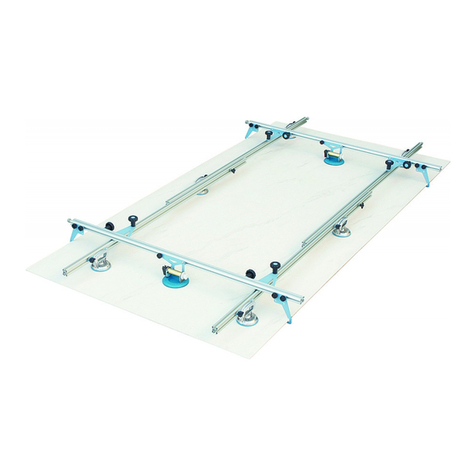
Sigma KERA-LIFT 1A4 User manual

®
ISTRUZIONI PER L’USO
DELL’ATTREZZATURA KERA-LIFT
ART. 1A4 / 1A5 / 1D2
INSTRUCTIONS FOR USE
KERA-LIFT ART. 1A4 / 1A5 / 1D2

Istruzioni per l’uso dell’attrezzatura KERA-LIFT Art. 1A4/ 1A5/1D2.
Instructions for use KERA-LIFT Art. Art. 1A4/ 1A5/1D2.
Mode d'employ KERA-LIFT Art. 1A4/ 1A5/1D2.
Gebrauchsanweisung KERA-LIFT Art. 1A4/ 1A5/1D2.
Attrezzatura con ventose per il sollevamento, la movimentazione e la posa di grandi piastrelle, liberamente
modificabile senza l’uso di utensili, è composta da guide scorrevoli fra loro per adattarsi a qualsiasi forma
della lastra.
Equipment with suction cups for lifting, handling, and laying of large tiles, freely modifiable without the use
of tools, is composed by guides sliding between them to adapt to any shape of the slab.
Équipement avec des ventouses pour le levage, la manipulation et l’installation de grandes tuiles, librement
modifiables sans l’utilization d’outils, est composé de rails de glissement pour s’adapter à n’importe quelle
forme de la dalle.
Vorkehrung mit Saugnäpfen zum Heben, Bewegen und Verlegen von großen Platten; durch die zwei
untereinander verschiebbaren Führungen die ohne jeglichem Werkzeug verstellt werden können, kann
diese Vorkehrung jeder beliebigen Plattenform angepasst werden.
ART. 1D2
ART. 1A5
ART. 1A4
2

LIMITI DI UTILIZZO : LIMITES D'UTILISATION :
USE LIMITS: NUTZUNGSGRENZEN :
ART. 1D2
ART. 1A4
ART. 1A5
portata Max:
150 Kg.
3

4
MONTAGGIO : MONTAGE:
ASSEMBLY : MONTAGE:
Posizionare i pezzi come in figura.
Place the pieces as shown in the figure.
Placez les pièces comme indiqué sur la figure.
Platziere die Teile wie in der Abbildung gezeigt.
Inserire i traversi nel primo longherone estensibile.
Insert the crossbars into the first extendable longitudinal member.
Insérer les traverses sur la première barre longitudinale.
Stecken Sie die beiden Profile in die Halterungen.
Inserire il traverso nel secondo longherone estensibile e
bloccare i pomoli.
Insert the crossbars into the second extendable longitudinal
member and lock the knobs.
Insérer les traverses sur la deuxième barre longitudinale et
serrer les boutons.
Stecken Sie die beiden Profile in die Halterungen.
Adattare il telaio alla lastra.
Adapt to the tile shape.
Adapter le cadre à la dalle.
Passen Sie den Rahmen an die
fliesen.
1
Se presenti inserire le ventose centrali.
If present, insert the central suction cups.
Si fournis, insérez les ventouses centrales.
Falls vorhanden, setzen Sie die zentralen Saugnäpfe ein.
3
2
4
5

Posizionare il telaio facendo sporgere i piedi in gomma 1,5
cm fuori dalla piastrella.
Position the frame with the rubber feet 1.5
cm outside the tile.
Positionner le cadre avec le pied en caoutchouc qui dépasse la
dalle d'environin 1,50 cm.
Positionieren Sie den Rahmen so, dass die Gummifüße 1,5
cm aus der Fliese herausragen.
1
2.2
Appoggiare la lastra sul lato lungo della cassa e applicarvi il
telaio.
Place the slab on the long side of the wood case and apply
the frame.
Placer la dalle sur le côté long de la boîte et appliquer le
cadre.
Legen Sie die Platte auf die lange Seite des Gehäuses und
befestigen Sie den Rahmen daran.
2.3
In caso i traversi impediscano la presa della lastra come in
figura.
If the crossbars prevent the liftinging of the slab like in figure
Dans le cas où le traverse empêche l'adhérence de la dalle
comme dans la figure
Wenn die Balken verhindern, dass die Platte wie in der
Abbildung gezeigt greift
PRESS
PRESS
1
2
1
2
2
Mettere in depressione le ventose
spingendo sul corpo della ventosa.
Depress the suction cups
pushing on the body of the suction cup.
Dépressuriser les ventouses en poussant
sur leur corps.
Drücken Sie die Saugnäpfe durch Drücken
auf den Saugnapfkörper.
CASI PARTICOLARI : UTILISATION :
PARTICULAR CASES : SONDERFÄLLE :
PRESS
LAVORAZIONE : UTILISATION :
WORKING : PROCESSING :
5

Prima di stendere la colla RIMUOVERE LE SICURE;
Stendere la colla.
Before apply the glue REMOVE THE SAFETY BRACKETS;
Apply the glue.
RETIRER LES DISPOSITIFS DE SÉCURITÉ avant de
appliquer la colle.
Vor dem Aufkleben SICHERHEIT ENTFERNEN; Lege den
Kleber ein.
Posa della lastra (orizzontale).
Laying of the slab (horizontal).
Pose de la dalle (horizontale).
Verlegen der Platte (horizontal).
Posizionare le sicure come figura "A" o come in figura
“B” e portarsi nella zona di posa.
Place the safety brackets as figure "A" or as in figure “B”,
e portarsi nella zona di posa.
Positionner les dispositifs de sécurité comme figure "A"
ou "B", et passer à la zone d’installation.
Platzieren Sie die Schutzeinrichtungen wie "A" oder wie
in Abbildung “B”, Bewegen Sie sich in den Legebereich.
A
B
3
4
5.1
6
Posa della lastra (verticale).
Laying of the slab (vertical).
Pose de la dalle (verticale).
Verlegen der Platte (senkrecht).
5.2
In caso di movimentazione di un pezzo di lastra, è sufficiente
smontare uno dei longheroni estensibili.
In the case of handling a piece of slab, it is sufficient
dismantle one of the extendable side members.
En cas de manipulation d'une partie de la dalle, il suffit de
démonter l'un des deux barres longitudinales.
Bei der Handhabung eines Brammenstücks genügt es, einen
der ausziehbaren Längsträger zu demontieren.
6

1) La superficie dell’oggetto da sollevare deve essere pulita e asciutta.
1) The surface of the object to be lifted must be clean and dry.
1) La surface de l'objet à soulever doit être propre et sèche.
1) Die Oberfläche des zu hebenden Objekts muss sauber und trocken sein.
2) Tenere la ventosa pulita e lontana da polveri ed acqua.
2) Keep the suction cup clean and away from dust and water.
2) Garder la ventouse propre et loin de la poussière et de l'eau.
2) Halten Sie den Saugnapf sauber und von Staub und Wasser fern.
3) Maneggiare la ventosa con cura onde evitare di danneggiare la superficie di presa, in particolar modo i bordi di
gomma in rilievo.
3) Handle the suction cup with care, to avoid damage to the grip surface, especially the raised rubber edges.
3) Manipuler la ventouse avec précaution, afin d'éviter d'endommager la surface de préhension, en particulier les bords
en caoutchouc en relief.
3) Behandeln Sie den Saugnapf vorsichtig, um Beschädigungen der Greiffläche, insbesondere der erhöhten
Gummikanten, zu vermeiden.
4) Evitare urti o cadute della ventosa.
4) Avoid bumps or falls of the suction cup.
4) Eviter les bosses et les chutes des ventouses.
4) Vermeiden Sie Schläge oder Erstickungsstürze.
5) Evitare esposizioni prolungate ai raggi solari e freddo intenso.
5) Avoid prolonged exposures to sunlight and intense cold.
5) Eviter expositions prolongées à la lumière du soleil ou au froid intense.
5) Vermeiden Sie längere Sonneneinstrahlung und starke Kälte.
6) In caso il pistone fuoriuscisse rapidamente pur essendo
la ventosa in presa, pulire e lubrificare la guarnizione
indicata.
6) In case the piston quickly comes out even though the
suction cup is sucking, clean and lubricate the indicated
gasket.
6) Au cas où le piston sortirait rapidement, même si la
ventouse est en prise, nettoyer et lubrifier le joint
d'étanchéité indiqué.
6) Falls sich der Kolben schnell dreht, obwohl sich der
Saugnapf in der Fassung befindet, reinigen und schmieren
Sie die angegebene Dichtung.
CONSIGLI PER EVITARE PERDITE DI PRESTAZIONI DELLE VENTOSE:
RECOMMENDATIONS TO AVOID LOSSES OF SUCTION CUP'S PERFORMANCES:
CONSEILS POUR EVITER LA PERTE DE PERFORMANCE DES VENTOUSES:
RATSCHLÄGE ZUR VERMEIDUNG VON LEISTUNGSVERLUSTEN:
7

Inserire le maniglie Art. 424 (optional) stringere i pomoli.
Insert the handles Art. 424 (optional) tighten the knobs.
Insérer les poignées Art. 424 (en option) et serrer les boutons.
Die Griffe Art. 424 (optional) einsetzen und die Knöpfe festziehen.
Il Kit Carrello Art. 421 permette la movimentazione del telaio in maniera
facile e sicura.
Grazie alla ruota girevole è possibile l’esecuzione di percorsi con curve.
I cavalletti permettono il perfetto sostegno della lastra anche in fase di
stesura della colla, sono presenti due sicure Anti-caduta rivestite in
gomma.
The Carriage Kit Art. 421 allows the movement of the frame in a easy and
safe way.
Thanks to the rotating wheel it is possible to run route with curves.
The trestles allow the perfect support of the slab even during the
applaying of the
glue, there are two safe Anti-fall brackets coated in rubber.
Le kit chariot Art. 421 permet de déplacer le cadre facilement et en toute
sécurité. Grâce à la roue pivotante, il vous permet de vous déplacer dans
les courbes. Les supports permettent un support parfait de la dalle, même
lors de l'application de la colle; il y a deux dispositifs antichutes recouverts
de caoutchouc.
Das Trolley-Kit Art. 421 ermöglicht die Bewegung des Rahmens auf eine
Art und Weise einfach und sicher.
Dank des drehbaren Rades können Bahnen mit Kurven gefahren
werden.
Die Böcke ermöglichen die perfekte Unterstützung der Platte, auch wenn
der Leim verlegt wird. Es gibt zwei sichere, mit Gummi beschichtete Anti-
Fall-Materialien.
ART. 424
KIT MANIGLIE - HANDLES KIT
KIT CARRELLO - CARRIAGE KIT
8
ACCESSORI ACCESSOIRES
ACCESSORIES ZUBEHÖR
ART. 421

9

10

11

Istruzioni per l’installazione, l’uso e la manutenzione
manuale di istruzioni per l'uso tradotto dalla lingua italiana
Accessorio di sollevamento
Kera lift 1A4 /1A5 /1D2
INDICE
0.0. INTRODUZIONE.
1. 0. REQUISITI ESSENZIALI DI SICUREZZA E DI TUTELA DELLA SALUTE.
1.1. INTEGRAZIONE DELLA SICUREZZA.
1.2. INFORMAZIONI E SICUREZZA DELLA MACCHINA PER IL SOLLEVAMENTO DI
PIASTRELLE.
1.2.1. USO PREVISTO DELLA MACCHINA PER IL SOLLEVAMENTO DI PIASTRELLE.
1.2.2. INDICAZIONI E CONTROINDICAZIONI. 1.3.PARTI PRINCIPALI DELLA MACCHINA PER
IL SOLLEVAMENTO DI PIASTRELLE.
1,3,1 MATERIALI CHE COMPONGONO LA MACCHINA
1,3,2 SMALTIMENTO
1.4. PRESCRIZIONI PER LA SICUREZZA.
1.4.1. INSTALLAZIONE.
1.4.2. TRASPORTO E DISIMBALLAGGIO DELLA MACCHINA.
3.ACCESSORI.
1,4,3,1 MONTAGGIO COMPONENTI
1.4.4. POSIZIONAMENTO.
2.0. SISTEMI DI SICUREZZA DELLA MACCHINA PER IL SOLLEVAMENTO DI PIASTRELLE.
2.1. TARGHE DI IDENTIFICAZIONE.
3.0. DATI TECNICI.
4.0. COME PREPARARSI AL LAVORO.
4.1. PRECAUZIONI PER LA MOVIMENTAZIONE.
6.0. MANUTENZIONE.
7.0. DIAGNOSTICA.
7,1 ASSISTENZA.
7,1,1 AGGIORNAMENTO DEL MANUALE
7,2 PROCESSO DI FABBRICAZIONE.
7,3 COLLABORAZIONE CON L’UTENTE
8.2. TAVOLE PARTI DI RICAMBIO.
CERTIFICATO DI GARANZIA.
0.1. DICHIARAZIONE CE DI CONFORMITÀ.
0.0. INTRODUZIONE.
Questo manuale di istruzioni è indirizzato all'utente della macchina e contiene tutte le informazioni
che riguardano l'installazione, l'uso e la manutenzione, corredate da tutte le indicazioni necessarie in
materia di sicurezza.
Il manuale di istruzioni deve essere conservato nelle vicinanze della macchina, al riparo da sporco e
umidità, sempre a disposizione per qualsiasi riferimento.
Questa macchina deve essere destinata solo all' uso per il quale è stata espressamente concepita.
Ogni altro uso si considera improprio e quindi pericoloso. Il fabbricante non può essere considerato
responsabile per eventuali danni derivanti da usi impropri o a seguito della mancata osservanza
delle norme di sicurezza e d'uso indicate nel presente manuale di istruzioni.
-- All'interno di questo manuale di istruzioni, Il carattere evidenziato, serve ad evidenziare un'
importante avvertenza a cui prestare particolare attenzione.
-- Sulla macchina è apposto un adesivo con :
-- Il simbolo CE che attesta la rispondenza della macchina alle normative comunitarie in vigore al
momento della costruzione della macchina.
-- Il simboli circolari di obbligo , servono a segnalare l' obbligo dell'uso di sistemi di protezione quali
guanti pantaloni scarpe e occhiali.
-- Il simbolo circolare con un libro, segnala la presenza del manuale di istruzioni e quindi ne obbliga
la lettura prima della installazione o uso della macchina.
-- Il simbolo rettangolare con indicata la portata massima .
1. 0. REQUISITI ESSENZIALI DI SICUREZZA E DI TUTELADELLA SALUTE.
1.1. INTEGRAZIONE DELLA SICUREZZA.
La macchina è stata progettata per essere atta a funzionare, ad essere azionata, ad essere regolata
e a subire la manutenzione, se effettuate nelle condizioni previste, senza che tali operazioni possano
esporre a rischi le persone, tenendo anche conto dell'uso scorretto ragionevolmente prevedibile.
Le misure adottate hanno lo scopo di eliminare ogni rischio durante l'esistenza prevedibile della
macchina, comprese le fasi di trasporto, montaggio, smontaggio, smantellamento (messa fuori
servizio) e rottamazione.
La macchina è progettata e costruita tenendo conto delle limitazioni imposte all'operatore dall'uso
necessario o prevedibile delle attrezzature di protezione individuale.
La macchina è fornita completa di tutte le attrezzature e gli accessori speciali essenziali per poterla
regolare, eseguirne la manutenzione e utilizzarla in condizioni di sicurezza .
1.2. INFORMAZIONI E SICUREZZA DELLAMACCHINA PER IL SOLLEVAMENTO DI
PIASTRELLE.
Leggere attentamente questo manuale prima dell'installazione della macchina e conservarlo per
futuri riferimenti.
1.2.1. USO PREVISTO DELLA MACCHINA PER IL SOLLEVAMENTO DI PIASTRELLE.
La macchina può essere impiegata per il sollevamento e movimentazione di piastrelle di grande
formato.
1.2.2. INDICAZIONI E CONTROINDICAZIONI.
Devono essere abilitati all'uso della macchina solamente:
1 addetti in numero tale da limitare lo sforzo a 25kg per gli uomini e 20 kg per le donne.
2 addetti con istruzione scolastica adeguata a comprendere integralmente le
informazioni contenute nel presente manuale ( minimo consigliata: licenza di scuola inferiore)
3 addetti che abbiano ricevuta una istruzione all'uso della macchina da personale
responsabile ed esperto.
4 E vietato sollevare la macchina con sistemi quali argani, elevatori carrucole, diversi dalle
mani degli operatori.
5 E vietato sollevare la macchina e il suo carico ad altezze maggiori di metri 1,1 da terra
6 è obbligatorio l'uso di occhiali, scarpe antinfortunistiche, guanti e pantaloni lunghi.
7 Bloccare tutti i pomoli prima di sollevare la piastrella.
8 Prima di sollevare un nuovo materiale occorre testare la durata di presa delle ventose,
agganciando una piastrella e mantenendola sollevata 5 cm. da terra per un tempo triplo, rispetto a
quello poi necessario per la movimentazione.
Questo perché, se la durata di tenuta del vuoto è di ore, su un materiale liscio , con le ventose nuove ,
tale durata si può ridurre a pochi secondi su piastrelle molto rugose o usando ventose con gomma
vecchia o usurata.
10 Questa macchina non può essere utilizzata per il sollevamento di materiali porosi
11 La macchina non può essere utilizzata in modi diversi da quelli per cui è stata progettata.
12 Non eseguire sollevamento di materiali il cui peso e dimensioni non sono proporzionati
alla struttura della macchina.
13 Non sollevare con temperatura ambiente, o dei materiali, inferiore a 5° o superiore a 50°.
inoltre è bene che materiale e ventose siano puliti ed asciutti.
14 Ogni modifica che alteri le caratteristiche della macchina deve essere effettuata solo dal
costruttore che ne attesterà la conformità. Pertanto ogni modifica o intervento di manutenzione non
compreso nel presente manuale è da considerare arbitraria.
15 La portata è garantita alla altitudine massima di 1000 mt. sul livello del mare
16 Non appoggiare le ventose su superfici bagnate da sostanze chimiche diverse dall'acqua.
17 per pulire le gomme delle ventose usare solamente acqua e sapone da cucina.
1.3. PARTI PRINCIPALI DELLAMACCHINAPER IL TAGLIO DI PIASTRELLE.
La macchina è composta dalle seguenti parti principali:
Estrusi longitudinali e/o trasversali
Ventose
Sicure Anti caduta
--) - Ulteriori particolari sono identificabili negli esplosi allegati.
1.3.1. Materiali che compongono la macchina:
Acciaio Ac
Alluminio Al
Gomma stirolo SBR
Nylon PA
5.0. SMALTIMENTO
Quando si smantella la macchina destinare ogni componente al riciclo corrispondente per evitare
l'inquinamento ambientale.
Sono disponibili schede di fine vita sul nostro sito: www.sigmaitalia.com
1,4 PRESCRIZIONI PER LASICUREZZA.
1.4.1. INSTALLAZIONE.
1.4.2. TRASPORTO E DISIMBALLAGGIO DELLA MACCHINA.
La macchina può arrivare imballata dentro una scatola di cartone.
Controllare l' integrità dell' imballo assicurandosi visivamente che non vi siano danni evidenti subiti
durante il trasporto e togliere la macchina dall'imballo.
ATTENZIONE: provvedere all'eliminazione degli elementi dell'imballo che possono essere fonte
di pericolo.
1.4.3. ACCESSORI.
Verificare la presenza di tutti gli accessori all' interno della macchina:
Manuale di istruzioni +
diverse sicurezze anti caduta sottili
1,4,3,1 MONTAGGIO COMPONENTI
Per facilitare il trasporto, la macchina può essere stata parzialmente smontata,
seguire le immagini come istruzioni di montaggio.
1.4.4. POSIZIONAMENTO.
Identificare una zona in piano sufficientemente larga, con fondo liscio, solido e in piano. Preferibilmente
al riparo da pioggia o neve.
Sgomberare l' area di lavoro da oggetti che possono essere fonte di pericolo e di inciampo.
Assicurarsi sempre che il piano ove si colloca la macchina sia di portata sufficiente al peso da
sostenere e che permetta la necessaria stabilità.
Mantenere pulita e illuminare adeguatamente l' area di lavoro.
2.0. SISTEMI DI SICUREZZA DELLAMACCHINAPER IL SOLLEVAMENTO DI PIASTRELLE.
La macchina è dotata dei seguenti dispositivi di protezione di tipo meccanico:
Sono presenti diverse sicurezze anti caduta fissabili sia agli estrusi bassi , che agli estrusi alti.
E' consigliabile montarli sui lati lunghi della piastrella
3.0. DATI TECNICI
Modello 1A4 rev.0
Dimensioni sollevabili mm. 3400x1500
Massa macchina Kg. 19
Massa max. sollevabile Kg. 100
Modello 1A5 rev.0
Dimensioni sollevabili mm. 3400x1500
Massa macchina Kg. 22
Massa max. sollevabile Kg. 150
Modello 1D2 rev.0
Dimensioni sollevabili mm. 3200x1000
Massa macchina Kg. 6
Massa max. sollevabile Kg. 40
COME PREPARARSI AL LAVORO.
Pulire e asciugare la piastrella da sollevare
Pulire e asciugare la gomma delle ventose
Distribuire le ventose seguendo le immagini allegate.
Sigma Accessorio di sollevamento Kera lift 1A4 1A5 1D2 REV.0 ITALIANO
12

Appoggiare la macchina sulla piastrella.
Premere con forza ogni ventosa sulla piastrella e contemporaneamente azionare la leva e/o
stantuffo.
In caso di azionamento dello stantuffo, si considera una tenuta sufficiente quando l’anello rosso
scompare.
Controllare visivamente e con le mani, che tutte le ventose abbiano aderito alla piastrella.
Quando si solleva un nuovo materiale , lasciarlo sollevato 5 cm. da terra per almeno un tempo
triplo , rispetto a quello necessario poi per lo spostamento e lavorazione, per accertarsi che la presa
resista per un tempo sufficiente.
4.1. PRECAUZIONI PER LA MOVIMENTAZIONE.
Sollevare macchina e piastrella piegando le ginocchia e mantenendo la schiena verticale.
Evitare il passaggio del carico sospeso sopra a persone o luoghi per i quali la eventuale caduta del
carico può costituire pericolo.
Sono disponibili schede di fine vita sul nostro sito: www.sigmaitalia.com
6.0. MANUTENZIONE e STOCCAGGIO.
Non lasciare la macchina incustodita e non permettere che questa sia usata da estranei o
incapaci.
Quando la macchina è inutilizzata posizionarla in modo da evitare che il bordo delle ventose tocchi
spigoli che ne possono causare una deformazione permanente.
Nel caso questo accada, smontare la ventosa e metterne a bagno la parte in gomma in acqua
bollente per almeno 10 minuti, lasciarla raffreddare senza che appoggi sul bordo di tenuta.
Non lasciare la macchina esposta ad agenti atmosferici (pioggia, sole, umidità, ecc..).
7.0. DIAGNOSTICA.
PROBLEMA
CAUSA
RIMEDIO
La ventosa non rimane agganciata alla piastrella.
Il labbro della ventosa è danneggiato
Sostituire la gomma della ventosa
La ventosa non rimane agganciata alla piastrella.
La piastrella è porosa
Non è possibile sollevare questo materiale
La ventosa non rimane agganciata alla piastrella.
La piastrella è talmente rugosa da impedire il vuoto fra la ventosa e la superficie della piastrella
Pulire meglio le superfici in contatto oppure richiedere al fornitore una ventosa alternativa con
maggiore capacità di adattamento al materiale.
La maniglia della ventosa non rimane agganciata in posizione verticale
La maniglia è consumata
Sostituire la maniglia
Difficile scorrimento telescopico degli estrusi longitudinali
presenza di sporco nelle guide
pulire le guide e lubrificarle con del WD40 o lubrificante equivalente
7.1 ASSISTENZA.
Per qualsiasi richiesta, necessità o informazione, l'utilizzatore deve comunicare al rivenditore di zona
o al fabbricante i seguenti dati:
Modello della macchina
Anno di costruzione
Data di acquisto
Numero ore di servizio, approssimativo
Indicazioni dettagliate del difetto riscontrato.
7,2 AGGIORNAMENTO DEL MANUALE
Il manuale rispecchia lo stato dell’arte al momento della immissione sul mercato della
macchina della quale è parte integrante ed è conforme a tutte le leggi, direttive, norme vigenti in quel
momento; non potrà essere considerato inadeguato solo perché successivamente aggiornato in
base a nuove esperienze. Eventuali modifiche, aggiornamenti, ecc. che venissero apportate alle
macchine commercializzate successivamente non obbligano il Costruttore ad intervenire
sull’apparecchiatura fornita in precedenza, né a considerare la stessa ed il relativo manuale
carenti ed inadeguati.
Eventuali integrazioni del manuale che il Costruttore riterrà opportuno di inviare agli utenti
dovranno essere conservate insieme al manuale di cui faranno parte integrante.
7,3 COLLABORAZIONE CON L’UTENTE
Il Costruttore è a disposizione della propria clientela per fornire ulteriori informazioni e per
considerare proposte di miglioramento al fine di rendere questo manuale più rispondente alle
esigenze per le quali è stato preparato. In caso di cessione della apparecchiatura l’utente primario
è invitato a segnalare al Costruttore l’indirizzo del nuovo utilizzatore affinché sia possibile
raggiungerlo con eventuali comunicazioni e/o aggiornamenti ritenuti indispensabili.
7.4. PROCESSO DI FABBRICAZIONE.
La macchina costruita dalla sigma è stata valutata già in fase di progettazione, ed è stato costituito
un fascicolo tecnico che riguarda tutti gli aspetti che concorrono alla sicurezza . In fase di
fabbricazione sono eseguiti tutti i controlli necessari a garantire la perfetta rispondenza della
macchina agli standard di precisione e sicurezza previsti nel fascicolo tecnico.
8.2. TAVOLE PARTI DI RICAMBIO.
Nelle ultime pagine troverete le tavole delle varie parti che compongono la macchina, unitamente
alle relative descrizioni.
In caso di richiesta di parti di ricambio, allo scopo di evitare possibili confusioni e malintesi, Vi
preghiamo di specificare il numero di codice del pezzo rilevabile dalla tavola, oltre ai dati di targa
della macchina.
La colonna relativa alle quantità indica, per ogni parte, il totale dei pezzi uguali presenti sulla
macchina.
Ogni componente complesso è indicato sopra ai componenti semplici che lo compongono.
9.0. CERTIFICATO DI GARANZIA.
Macchina di sollevamento modello 1A4 /1A5 / 1D2
La società sigma garantisce l'ottima qualità e il perfetto funzionamento della macchina modello. 1A4
/ 1A5 / 1D2
alle seguenti condizioni:
La garanzia ha la durata di 24 mesi a decorrere dalla data di vendita all'utilizzatore finale.
La sigma si impegna a riparare o sostituire gratuitamente ogni parte meccanica che risultasse
difettosa di fabbrica da un esame dei suoi tecnici.
La garanzia cessa il suo effetto quando la macchina o parti di essa venissero modificate o
manomesse da personale non autorizzato.
La garanzia non risponde per eventuali rotture o disfunzioni dipendenti da una cattiva manutenzione
o da un uso improprio della macchina.
Le spese di trasporto o imballo per l'eventuale ritorno in fabbrica di pezzi in riparazione o sostituzione
e per la loro successiva restituzione rimangono a carico dell'acquirente.
la garanzia di buon funzionamento dipende dalla
corretta applicazione delle istruzioni contenute nel presente manuale.
Con riferimento a quanto riportato nel presente manuale di istruzioni:
il Costruttore declina ogni responsabilità in caso di :
- uso contrario alle leggi nazionali sulla sicurezza e sull’antinfortunistica.
- errata predisposizione delle strutture di sollevamento
- mancata o errata osservanza delle istruzioni fornite nel presente manuale.
- modifiche non autorizzate
- uso di pezzi di ricambio non originali.
- danni imputabili a eccessive sollecitazioni dinamiche statiche dell’accessorio di sollevamento
Apporre qui il timbro del venditore
Annotare qui la data di vendita
Apporre qui la firma del venditore
DICHIARAZIONE
CE DI CONFORMITÀ
IL FABBRICANTE
(All. IIA DIR. 2006/42/CE)
Azienda: sigma di S. Ambrogiani & C. sas
Indirizzo: Via Gagliani 4
Città: Bellaria Igea Marina
Cap: 47814
Provincia: RN
Stato: Italia
DICHIARA CHE LA MACCHINA
Descrizione: accessorio per il sollevamento di piastrelle
Serie: ( vedi targa 1 )
Denominazione commerciale - Modello: KERALIFT 1A4
Anno di costruzione : ( vedi targa 1 )
Revisione: 0
Uso previsto: Sollevamento manuale di piastrelle
Descrizione: accessorio per il sollevamento di piastrelle
Serie: ( vedi targa 1 )
Denominazione commerciale - Modello: KERALIFT 1A5
Anno di costruzione : ( vedi targa 1 )
Revisione: 0
Uso previsto: Sollevamento manuale di piastrelle
Descrizione: accessorio per il sollevamento di piastrelle
Serie: ( vedi targa 1 )
Denominazione commerciale - Modello: KERALIFT 1D2
Anno di costruzione : ( vedi targa 1 )
Revisione: 0
Uso previsto: Sollevamento manuale di piastrelle
È CONFORME ALLE DIRETTIVE
Direttiva 2006/42/CE del Parlamento Europeo e del Consiglio del 17 maggio 2006 relativa alle
macchine e che modifica la direttiva 95/16/CE.
Riferimento norme armonizzate:
UNI EN ISO 12100-1 Rev. (0405) Sicurezza del macchinario - Concetti fondamentali, principi
generali di progettazione
E AUTORIZZA
Nominativo: Valter Ambrogiani
Indirizzo: Via Castellabate 18a
Città: Bellaria Igea Marina
Cap: 47813
Provincia: RN
Stato: Italia
A COSTITUIRE IL FASCICOLO TECNICO PER SUO CONTO
Luogo e data del documento:
Bellaria 07/07/2016
Il fabbricante
Sigma Accessorio di sollevamento Kera lift 1A4 1A5 1D2 REV.0 ITALIANO
13

Instructions for installation, operation and maintenance
instruction manual for use translated from Italian
Lifting accessory
Kera lift 1A4 /1A5 / 1D2
INDEX
0.0. INTRODUCTION.
1. 0. ESSENTIAL SAFETYAND HEALTH REQUIREMENTS.
1.1. INTEGRATION OF SECURITY.
1.2. INFORMATION AND SAFETY OF MACHINE LIFTING MACHINE.
1.2.1. USE OF MACHINE LIFTING MACHINE.
1.2.2. INDICATIONS AND CONTRAINDICATIONS. 1.3 MAIN PLANTS FOR THE PLATE
LIFTING MACHINE.
1.3.1 MATERIALS COMPONENT THE MACHINE
1,3,2 DISPOSAL
1.4. SAFETY REQUIREMENTS.
1.4.1. INSTALLATION.
1.4.2. MACHINE TRANSPORT AND DISABLING.
ACCESSORIES.
1.4.3.1 ASSEMBLING COMPONENTS
1.4.4. POSITIONING.
2.0. MACHINE SAFETY SYSTEMS FOR PLASTER LIFTING.
2.1. IDENTIFICATION TARGETS.
3.0. TECHNICAL DATA.
4.0. HOW TO PREPARE FOR WORK.
4.1. HANDLING PRECAUTIONS.
6.0. MAINTENANCE.
7.0. DIAGNOSTICS.
7.1 ASSISTANCE.
7.1.1 MANUAL UPDATE
7.2 MANUFACTURING PROCESS.
7.3 COLLABORATION WITH USER
8.2. TABLES PARTS OF REPLACEMENT.
WARRANTY CERTIFICATE.
0.1. EC DECLARATION OF CONFORMITY.
0.0. INTRODUCTION.
This instruction manual is addressed to the user of the machine and contains all the
information regarding the installation, use and maintenance, accompanied by all the
necessary safety information.
The instruction manual must be kept close to the machine, protected from dirt and moisture,
always available for any reference.
This machine should only be used for the purpose for which it was expressly designed.
Any other use is considered improper and therefore dangerous. The manufacturer can not
be held responsible for any damage resulting from improper use or as a result of non-
compliance with the safety and operating rules stated in this instruction manual.
- Within this instruction manual, the highlighted character serves to highlight an important
warning to be given special attention.
- A sticker is attached to the machine with:
- The EC symbol attesting the conformity of the machine with the applicable Community
legislation at the time of construction of the machine.
- The circular symbols of obligation, serve to signal the obligation of the use of protective
systems such as gloves trousers shoes and glasses.
- The circular symbol with a book, indicates the presence of the instruction manual and
therefore requires reading before installing or using the machine.
- The rectangular symbol with the maximum flow rate indicated.
1. 0. ESSENTIAL SAFETY AND HEALTH REQUIREMENTS.
1.1. INTEGRATION OF SECURITY.
The machine is designed to be capable of being operated, operated, adjusted, and
maintained if carried out under the intended conditions, without the risk of exposing persons
to such persons, while also taking into account the reasonably foreseeable misuse.
The measures taken are intended to eliminate any risk during the foreseeable existence of
the machine, including the stages of transport, assembly, dismantling, dismantling
(dismantling) and scrapping.
The machine is designed and constructed taking into account the limitations imposed on the
operator by the necessary or predictable use of personal protective equipment.
The machine is supplied with all the essential equipment and accessories to be able to
adjust, maintain, and use it in safe conditions.
1.2. INFORMATION AND SAFETY OF MACHINE LIFTING MACHINE.
Read this manual carefully before installing the machine and store it for future reference.
1.2.1. USE OF MACHINE LIFTING MACHINE.
The machine can be used for lifting and handling large size tiles.
1.2.2. INDICATIONS AND CONTRAINDICATIONS.
Only the machine must be enabled:
1 in number to limit the effort to 25kg for men and 20kg for women.
2 pupils with adequate education to fully understand the information contained in this
manual (minimum recommended: lower school license)
3 employees who have received instruction on using the machine from responsible and
experienced personnel.
4 It is forbidden to lift the machine with systems such as winches, pulleys, other than
operator hands.
5 It is forbidden to lift the machine and its load at greater heights than 1.1 meters from the
ground
6 the use of glasses, safety shoes, gloves and long pants is compulsory.
7 Block all the knobs before lifting the tile.
8 Before lifting a new material, it is necessary to test the suction cup take-up time, engaging
a tile and keeping it 5 cm high. from the ground for a triple time, compared to the one then
needed for handling.
This is because, if the vacuum holding time is hours, on a smooth material with new suction
cups, this can be reduced to a few seconds on very rugged tiles or by using old or worn
rubber suction cups.
10 This machine can not be used for lifting porous materials
11 The machine can not be used in ways other than those for which it was designed.
12 Do not lift any material whose weight and dimensions are not proportional to the structure
of the machine.
13 Do not raise with room temperature or materials below 5 ° or greater than 50 °. It is also
good that the material and suction cups are clean and dry.
14 Any modification that alters the characteristics of the machine must only be carried out by
the manufacturer that will attest conformity. Therefore any modification or maintenance work
not covered in this manual is considered arbitrary.
15 The flow rate is guaranteed at a maximum altitude of 1000 m. on the sea level
16 Do not place suction cups on surfaces that are wet with chemicals other than water.
17 To clean the suction cups, use only water and kitchen soap.
1.3. MAIN PARTS OF PLATE CUTTING MACHINE.
The machine consists of the following main parts:
Longitudinal and / or transverse extrusions
Suction Cups
Safe Anti Fall
-) - Further details are identifiable in the enclosed explosions.
1.3.1. Materials that make up the machine:
Steel Ac
Aluminum Al
Rubber tire SBR
Nylon PA
5.0. DISPOSAL
When dismantling the machine, allocate each component to the corresponding recycle to
avoid environmental pollution.
End-of-life cards are available on our website: www.sigmaitalia.com
1.4 SAFETY REQUIREMENTS.
1.4.1. INSTALLATION.
1.4.2. MACHINE TRANSPORT AND DISABLING.
The machine can get packed inside a cardboard box.
Check the integrity of the packaging by making sure that no obvious damage has occurred
during transport and remove the machine from the packaging.
WARNING: Remove the packaging elements that may be a source of danger.
1.4.3. ACCESSORIES.
Check for all accessories inside the machine:
Instruction manual +
various anti falls
1.4.3.1 ASSEMBLING COMPONENTS
To facilitate transportation, the machine may have been partially disassembled,
follow the pictures as mounting instructions.
1.4.4. POSITIONING.
Identify a sufficiently wide planar area, with a solid, solid, flat surface. Preferably sheltered
from rain or snow.
Remove the work area from objects that can be a source of danger and stumbling.
Always make sure that the plane on which the machine is placed is of sufficient capacity to
the weight to support and that it will provide the necessary stability.
Keep clean and properly illuminate the work area.
2.0. MACHINE SAFETY SYSTEMS FOR PLASTER LIFTING.
The machine is equipped with the following mechanical protection devices:
There are several anti-fall safety devices available to both low extruded and high extruded.
It is advisable to mount them on the long sides of the tile.
The retaining tooth must fully engage the edge of the tile
2.1. IDENTIFICATION TARGETS
The machine identification plates are:
1 ° Fixing plate with the following information: A + B + C + D + E + F
2 ° Plaque plate on the fixing plate containing the identification information of the
manufacturer.
A) Model of the machine
B) Max lifting weight
C) Accessory weight
D) Year of construction
E) CE marking
F) Obligatory pictograms
: Whenever the manufacturer is questioned, it is indispensable to indicate the model of the
machine specified on the 1st identification plate.
3.0. TECHNICAL DATA
Model 1A4 rev.0
Lifting dimensions mm. 3400x1500
Mass machine Kg. 19
Mass max. liftable Kg. 100
Model 1A5 rev.0
Lifting dimensions mm. 3400x1500
Mass machine Kg. 22
Mass max. liftable Kg. 150
Model 1D2 rev.0
Lifting dimensions mm. 3200x1000
Machine mass Kg. 6
Mass max. liftable Kg. 40
Sigma Lifting accessory Kera lift 1A4 1A5 1D2 REV.0 ENGLISH
14

HOW TO PREPARE FOR WORK.
Clean and dry the tile to be lifted
Clean and dry the suction cups
Distribute the suction cups by following the attached pictures.
Place the machine on the tile.
Press each suction cup firmly on the tile and simultaneously actuate the lever and / or plunger.
In the case of piston actuation, it is considered a sufficient seal when the red ring disappears.
Check visually and with your hands that all the suction cups adhere to the tile.
When lifting a new material, leave it 5 cm high. from the ground for at least a triple time,
compared to what is necessary for moving and working, to ensure that the grip stays for a long
enough time.
4.1. HANDLING PRECAUTIONS.
Lifting machine and tile bending your knees and keeping your back vertical.
Avoid passing the suspended load over to people or places where a possible fall in the load may
be dangerous.
End-of-life cards are available on our website: www.sigmaitalia.com
6.0. MAINTENANCE AND STORAGE.
Do not leave the machine unattended and do not allow this to be used by strangers or incapable.
When the machine is unused, place it in such a way as to prevent the edge of the suction cups
from touching edges that can cause permanent deformation.
If this happens, disassemble the suction cup and bathe the rubber part in boiling water for at least
10 minutes, let it cool down without sticking to the sealing edge.
Do not leave the machine exposed to atmospheric agents (rain, sun, humidity, etc.).
7.0. DIAGNOSTICS.
PROBLEM
CAUSE
REMEDY
The suction cup does not remain attached to the tile.
The lip of the suction cup is damaged
Replace the suction cup
The suction cup does not remain attached to the tile.
The tile is porous
It is not possible to lift this material
The suction cup does not remain attached to the tile.
The tile is so rough that it prevents the vacuum between the suction cup and the tile surface
Clean the surfaces in contact or ask the supplier for a suction alternative with more material
adaptation capability.
The suction cup handle does not remain hooked vertically
The handle is worn
Replace the handle
Difficult telescopic sliding of longitudinal extrusions
dirt in the guides
clean the guides and lubricate them with the WD40 or equivalent lubricant
7.1 ASSISTANCE.
For any request, need or information, the user must inform the local retailer or manufacturer of the
following information:
Machine model
Year of construction
Date of purchase
Hours of service, approximate
Detailed fault information found.
7.2 MANUAL UPDATE
The manual reflects the state of the art when it is marketed, which is an integral part of it and
complies with all laws, directives, regulations in force at that time; can not be considered
inadequate only because it is subsequently updated based on new experiences. Any modi fi
cations, updates, etc. which were made to the machines subsequently marketed, do not oblige
the Manufacturer to intervene on the equipment previously supplied, nor to consider the same
and the related defective and inadequate manual.
Any additions to the manual that the Manufacturer will deem appropriate to send to users should
be kept together with the manual that will be included in the manual.
7.3 COLLABORATION WITH USER
The Manufacturer is at your disposal to provide additional information and to consider
suggestions for improvement to make this manual more responsive to the requirements for which
it has been prepared. If the equipment is sold, the primary user is encouraged to report to the
Builder the address of the new user so that it can be reached with any communications and / or
updates deemed necessary.
7.2. PROCESSING PROCESSING.
The Sigma-built machine has been evaluated in the design phase, and a technical file has been
set up covering all aspects of safety. At the manufacturing stage, all the controls necessary to
ensure the perfect match of the machine to the precision and safety standards in the technical file
are performed.
8.2. TABLES PARTS OF REPLACEMENT.
On the last pages you will find the tables of the various parts of the machine, along with their
descriptions.
In case of request for spare parts, in order to avoid possible confusion and misunderstanding,
please specify the part number code that can be detected by the board, in addition to the
machine's nameplate data.
The quantity column indicates, for each part, the total number of identical pieces on the machine.
Each complex component is indicated on the simple components that compose it.
9.0. WARRANTY CERTIFICATE.
Model lifting machine 1A4 / 1A5 / 1D2
The sigma company guarantees the excellent quality and perfect functioning of the model
machine. 1A4 / 1A5 / 1D2
under the following conditions:
The warranty period is 24 months from the date of sale to the end user.
The Sigma undertakes to repair or replace for free any mechanical parts that are found to be
defective in the factory from an examination by its technicians.
The warranty ceases to be effective when the machine or parts of it are modified or
tampered with by unauthorized personnel.
The warranty does not cover any malfunctions or malfunctions depending on poor
maintenance or improper use of the machine.
The shipping or packaging costs for the eventual return to the factory of parts for repair or
replacement and for their subsequent refund shall be borne by the buyer.
the guarantee of good operation depends on
correct application of the instructions contained in this manual.
Refer to the information in this instruction manual:
the Manufacturer declines any liability in case of:
- Use contrary to national safety and accident law.
- wrong predisposition of lifting structures
- Failure or incorrect observance of the instructions given in this manual.
- unauthorized modification
- Use of non-original spare parts.
- damages attributable to excessive static dynamic stresses of the lift accessory
Place the seller's stamp here
Write down the sales date here
Place here the signature of the seller
DECLARATION
THERE IS
OF CONFORMITY
THE MANUFACTURER
(IIA DIR. 2006/42 / EC)
Company: sigma di S. Ambrogiani & C. sas
Address: Via Gagliani 4
City: Bellaria Igea Marina
Cap: 47814
Province: RN
Country: Italy
DECLARES THAT THE MACHINE
Description: tile lift accessory
Series: (see plate 1)
Trade name - Model: KERALIFT 1A4
Year of construction: (see license plate 1)
Revision: 0
Expected use: Manual lifting of tiles
Description: tile lift accessory
Series: (see plate 1)
Trade name - Model: KERALIFT 1A5
Year of construction: (see license plate 1)
Revision: 0
Expected use: Manual lifting of tiles
Description: tile lift accessory
Series: (see plate 1)
Trade name - Model: KERALIFT 1D2
Year of construction: (see license plate 1)
Revision: 0
Expected use: Manual lifting of tiles
IS COMPLIANT WITH THE DIRECTIVES
Directive 2006/42 / EC of the European Parliament and of the Council of 17 May 2006 on
machinery and amending Directive 95/16 / EC.
Reference to harmonized standards:
UNI EN ISO 12100-1 Rev. (0405) Safety of machinery - Fundamental concepts, principles
general design
AND AUTHORIZES
Name: Valter Ambrogiani
Address: Via Castellabate 18a
City: Bellaria Igea Marina
Cap: 47813
Province: RN
Country: Italy
CONSTITUTE THE TECHNICAL DOCUMENT FOR ITS ACCOUNT
Place and date of the document:
Bellaria 07/07/2016
The manufacturer
Sigma Lifting accessory Kera lift 1A4 1A5 1D2 REV.0 ENGLISH
15

Instructions pour l'installation, l'utilisation et la maintenance
mode d'emploi traduit de l'italien
Accessoire de levage
Kera lift 1A4 / 1A5 / 1D2
TABLE DES MATIÈRES
0.0. INTRODUCTION.
1. 0. EXIGENCES ESSENTIELLES DE SÉCURITÉ ET DE SANTÉ.
1.1. INTÉGRATION DE LA SÉCURITÉ.
1.2. INFORMATION ET SECURITE DE LA MACHINE DE LEVAGE DE LA MACHINE.
1.2.1. UTILISATION DE LA MACHINE DE LEVAGE DE LA MACHINE.
1.2.2. INDICATIONS ET CONTRE-INDICATIONS. 1.3 PRINCIPALES USINES DE LA
MACHINE DE LEVAGE DES PLAQUES.
1.3.1 COMPOSANT DE MATÉRIAUX LA MACHINE
1,3,2 ÉLIMINATION
1.4. EXIGENCES DE SÉCURITÉ.
1.4.1. INSTALLATION.
1.4.2. MACHINE TRANSPORT ET DÉSACTIVATION.
ACCESSOIRES.
1.4.3.1 ASSEMBLAGE DES COMPOSANTS
1.4.4. POSITIONNEMENT.
2.0. SYSTÈMES DE SÉCURITÉ DE MACHINE POUR LE LEVAGE DE PLÂTRE.
2.1. CIBLES D'IDENTIFICATION.
3.0. DONNÉES TECHNIQUES
4.0. COMMENT SE PRÉPARER AU TRAVAIL.
4.1. PRÉCAUTIONS DE MANIPULATION.
6.0. ENTRETIEN.
7.0. DIAGNOSTICS.
7.1 ASSISTANCE.
7.1.1 MISE À JOUR MANUELLE
7.2 PROCESSUS DE FABRICATION.
7.3 COLLABORATION AVEC L'UTILISATEUR
8.2. TABLES DE PIÈCES DE REMPLACEMENT.
CERTIFICAT DE GARANTIE.
0.1. DÉCLARATION CE DE CONFORMITÉ.
0.0. INTRODUCTION.
Ce manuel d'instructions est adressé à l'utilisateur de la machine et contient toutes les
informations concernant l'installation, le fonctionnement et la maintenance, accompagnées de
toutes les informations de sécurité nécessaires.
Le manuel d'instructions doit être conservé à proximité de la machine, à l'abri de la saleté et de
l'humidité, toujours disponible pour toute référence.
Cette machine ne doit être utilisée que dans le but pour lequel elle a été conçue
expressément.
Toute autre utilisation est considérée comme inappropriée et donc dangereuse. Le fabricant ne
peut être tenu pour responsable des dommages résultant d'une utilisation non conforme ou du
non-respect des règles de sécurité et d'exploitation indiquées dans ce manuel d'instructions.
- Dans ce mode d'emploi, le caractère mis en évidence sert à mettre en évidence un
avertissement important nécessitant une attention particulière.
- Un autocollant est attaché à la machine avec:
- Le symbole CE attestant la conformité de la machine à la législation communautaire
applicable au moment de la construction de la machine.
- Les symboles circulaires d'obligation, servent à signaler l'obligation d'utiliser des systèmes de
protection tels que des gants, des pantalons, des chaussures et des lunettes.
- Le symbole circulaire avec un livre indique la présence du manuel d'instructions et nécessite
donc une lecture avant d'installer ou d'utiliser la machine.
- Le symbole rectangulaire avec le débit maximum indiqué.
1. 0. EXIGENCES ESSENTIELLES DE SÉCURITÉ ET DE SANTÉ.
1.1. INTÉGRATION DE LA SÉCURITÉ.
La machine a été conçu pour être adapté pour fonctionner, à entraîner, à ajuster et à subir
l'entretien sont effectués dans des conditions fixées, sans que ces opérations peuvent exposer
des personnes à risque, en tenant compte de tout mauvais usage raisonnablement prévisible.
Les mesures prises sont destinées à éliminer tout risque pendant l'existence prévisible de la
machine, y compris les étapes de transport, de montage, de démontage, de démontage et de
démolition.
La machine est conçue et construite en tenant compte des limitations imposées à l'opérateur
par l'utilisation nécessaire ou prévisible de l'équipement de protection individuelle.
La machine est fournie avec tous les équipements et accessoires essentiels pour pouvoir
l'ajuster, l'entretenir et l'utiliser dans des conditions de sécurité.
1.2. INFORMATION ET SECURITE DE LA MACHINE DE LEVAGE DE LA MACHINE.
Lisez attentivement ce manuel avant d'installer la machine et rangez-la pour référence
ultérieure.
1.2.1. UTILISATION DE LA MACHINE DE LEVAGE DE LA MACHINE.
La machine peut être utilisée pour soulever et manipuler des carreaux de grande taille.
1.2.2. INDICATIONS ET CONTRE-INDICATIONS.
Seule la machine doit être activée:
1 en nombre pour limiter l'effort à 25kg pour les hommes et 20kg pour les femmes.
2 élèves ayant reçu une éducation adéquate pour bien comprendre les informations contenues
dans ce manuel (minimum recommandé: licence d'école secondaire)
3 employés ayant reçu des instructions sur l'utilisation de la machine par du personnel
responsable et expérimenté.
4 Il est interdit de soulever la machine avec des systèmes tels que treuils, poulies, autres
que les mains de l'opérateur.
5 Il est interdit de soulever la machine et sa charge à plus de 1,1 mètre du sol
6 L'utilisation de lunettes, de chaussures de sécurité, de gants et de pantalons longs est
obligatoire.
7 Bloquer tous les boutons avant de soulever la dalle.
8 Avant de soulever un nouveau matériau, il est nécessaire de tester la durée de vie de la
ventouse en attachant un carreau et en le gardant à une hauteur de 5 cm. à partir du sol
pour un triple temps, par rapport à celui qui était alors nécessaire pour la manipulation.
En effet, si la durée du joint de vide est d'heures, sur un matériau lisse, avec les nouveaux
drageons, cette durée peut être réduite à quelques secondes sur les carreaux très rugueux
ou à l'utilisation de vieux ou usés ventouses en caoutchouc.
10 Cette machine ne peut pas être utilisée pour soulever des matériaux poreux
11 La machine ne peut pas être utilisée d'une autre manière que celles pour lesquelles elle
a été conçue.
12 Ne soulevez aucun matériau dont le poids et les dimensions ne sont pas proportionnels
à la structure de la machine.
13 Ne pas soulever avec la température ambiante ou des matériaux inférieurs à 5 ° ou
supérieurs à 50 °. Il est également bon que le matériau et les ventouses soient propres et
secs.
14 Toute modification modifiant les caractéristiques de la machine doit être effectuée
uniquement par le fabricant qui en attestera la conformité. Par conséquent, tout travail de
modification ou de maintenance non couvert dans ce manuel est considéré comme
arbitraire.
15 Le débit est garanti à une altitude maximale de 1000 m. au niveau de la mer
Ne placez pas les ventouses sur des surfaces humides avec des produits chimiques autres
que l'eau.
17 Pour nettoyer les ventouses, n'utilisez que de l'eau et du savon de cuisine.
1.3. PRINCIPALES PARTIES DE LA MACHINE DE COUPE DE PLAQUE.
La machine se compose des parties principales suivantes:
Extrusions longitudinales et / ou transversales
Coupes d'aspiration
Safe Anti Fall
-) - D'autres détails sont identifiables dans les explosions jointes.
1.3.1. Les matériaux qui composent la machine:
Acier Ac
Aluminium Al
Pneu en caoutchouc SBR
Nylon PA
5.0. ÉLIMINATION
Lors du démontage de la machine, attribuez chaque composant au recyclage correspondant
pour éviter la pollution de l'environnement.
Les cartes de fin de vie sont disponibles sur notre site internet: www.sigmaitalia.com
1.4 EXIGENCES DE SÉCURITÉ.
1.4.1. INSTALLATION.
1.4.2. MACHINE TRANSPORT ET DÉSACTIVATION.
La machine peut être emballée dans une boîte en carton.
Vérifiez l'intégrité de l'emballage en vous assurant qu'il n'y a pas eu de dommages évidents
pendant le transport et retirez la machine de l'emballage.
AVERTISSEMENT: Enlever les éléments d'emballage pouvant être une source de danger.
1.4.3. ACCESSOIRES.
Vérifiez tous les accessoires à l'intérieur de la machine:
Manuel d'instructions +
divers anti-chutes
1.4.3.1 ASSEMBLAGE DES COMPOSANTS
Pour faciliter le transport, la machine peut avoir été partiellement démontée,
suivez les photos comme instructions de montage.
1.4.4. POSITIONNEMENT.
Identifier une zone plane suffisamment large, avec une surface solide, solide et plate. De
préférence à l'abri de la pluie ou de la neige.
Enlevez la zone de travail des objets qui peuvent être une source de danger et de
trébuchement.
Assurez-vous toujours que le plan sur lequel la machine est placée est d'une capacité
suffisante pour le poids à supporter et qu'il fournira la stabilité nécessaire.
Gardez propre et éclairez correctement la zone de travail.
2.0. SYSTÈMES DE SÉCURITÉ DE MACHINE POUR LE LEVAGE DE PLÂTRE.
La machine est équipée des dispositifs de protection mécanique suivants:
Plusieurs dispositifs de sécurité anti-chute sont disponibles pour les extrudés à faible
extrusion et à haute extrusion.
Il est conseillé de les monter sur les côtés longs de la tuile.
La dent de retenue doit s'engager complètement sur le bord de la dalle
2.1. CIBLES D'IDENTIFICATION
Les plaques d'identification de la machine sont:
1 ° Plaque de fixation avec les informations suivantes: A + B + C + D + E + F
2 ° Plaque de plaque sur la plaque de fixation contenant les informations d'identification du
fabricant.
A) Modèle de la machine
B) Max poids de levage
C) Poids de l'accessoire
D) Année de construction
E) Marquage CE
F) Pictogrammes obligatoires
: Chaque fois que le fabricant est interrogé, il est indispensable d'indiquer le modèle de la
machine spécifié sur la 1ère plaque d’identification.
Sigma Accessoire de levage Kera lift 1A4 1A5 1D2 REV.0 FRANÇAIS
16

3.0. DONNÉES TECHNIQUES
Modèle 1A4 rev.0
Dimensions de levage mm. 3400x1500
Machine de masse Kg. 19
Masse max. relevable Kg. 100
Modèle 1A5 rev.0
Dimensions de levage mm. 3400x1500
Machine de masse Kg. 22
Masse max. relevable Kg. 150
Modèle 1D2 rev.0
Dimensions de levage mm. 3200x1000
Masse de la machine Kg. 6
Masse max. relevable Kg. 40
COMMENT SE PRÉPARER AU TRAVAIL.
Nettoyer et sécher la tuile à soulever
Nettoyez et séchez les ventouses
Répartissez les ventouses en suivant les images ci-jointes.
Placez la machine sur la tuile.
Pressez fermement chaque ventouse sur la dalle et actionnez simultanément le levier et / ou le
piston.
Dans le cas de l'actionnement du piston, il est considéré comme un joint suffisant lorsque
l'anneau rouge disparaît.
Vérifiez visuellement et avec vos mains que toutes les ventouses adhèrent à la tuile.
Lorsque vous soulevez un nouveau matériau, laissez-le 5 cm de haut. à partir du sol pendant au
moins un triple temps, par rapport à ce qui est nécessaire pour le déplacement et le travail, pour
s'assurer que la prise reste assez longtemps.
4.1. PRÉCAUTIONS DE MANIPULATION.
Levage de la machine et des carreaux en pliant les genoux et en gardant le dos vertical.
Évitez de faire passer la charge suspendue à des personnes ou à des endroits où une chute
possible de la charge peut être dangereuse.
Les cartes de fin de vie sont disponibles sur notre site internet: www.sigmaitalia.com
6.0. ENTRETIEN ET STOCKAGE.
Ne laissez pas la machine sans surveillance et ne permettez pas à celle-ci d'être utilisée par des
inconnus ou incapable.
Lorsque la machine n'est pas utilisée, placez-la de manière à éviter que le bord des ventouses ne
touche des bords susceptibles de provoquer une déformation permanente.
Si cela se produit, démonter la ventouse et baigner la pièce en caoutchouc dans de l'eau
bouillante pendant au moins 10 minutes, laisser refroidir sans coller au bord d'étanchéité.
Ne laissez pas la machine exposée à des agents atmosphériques (pluie, soleil, humidité, etc.).
7.0. DIAGNOSTICS. PROBLÈME CAUSE REMÈDE
La ventouse ne reste pas attachée à la tuile.
La lèvre de la ventouse est endommagée
Remplacer la ventouse
La ventouse ne reste pas attachée à la tuile.
La tuile est poreuse
Il n'est pas possible de soulever ce matériau
La ventouse ne reste pas attachée à la tuile.
La tuile est si rugueuse qu'elle empêche le vide entre la ventouse et la surface de la tuile
Nettoyer les surfaces en contact ou demander au fournisseur une alternative d'aspiration avec
plus de capacité d'adaptation du matériau.
La poignée de la ventouse ne reste pas accrochée verticalement
La poignée est usée
Remplacer la poignée
Glissement télescopique difficile des extrusions longitudinales
la saleté dans les guides
nettoyer les guides et les lubrifier avec le lubrifiant WD40 ou équivalent
7.1 ASSISTANCE.
Pour toute demande, besoin ou information, l'utilisateur doit informer le détaillant ou le fabricant
local des informations suivantes:
Modèle de machine
Année de construction
Date d'achat
Heures de service, approximatives
Informations détaillées sur les fautes trouvées.
7.2 MISE À JOUR MANUELLE
Le manuel reflète l'état de l'art lors de sa commercialisation, qui en fait partie intégrante et
respecte toutes les lois, directives et réglementations en vigueur à ce moment-là; ne peut être
considéré comme inadéquat uniquement parce qu'il est ensuite mis à jour en fonction de
nouvelles expériences. Toute modi fi cation, mise à jour, etc. qui ont été faites aux machines
commercialisées par la suite, n'obligent pas le fabricant à intervenir sur l'équipement
précédemment fourni, ni de considérer le même et le manuel défectueux et inadéquat.
Tout ajout au manuel que le fabricant jugera approprié d'envoyer aux utilisateurs doit être
conservé avec le manuel qui sera inclus dans le manuel.
7.3 COLLABORATION AVEC L'UTILISATEUR
Le fabricant est à votre disposition pour fournir des informations supplémentaires et pour
envisager des suggestions d'amélioration afin que ce manuel réponde mieux aux exigences pour
lesquelles il a été préparé. Si l'équipement est vendu, l'utilisateur principal est encouragé à
signaler au constructeur l'adresse du nouvel utilisateur afin qu'il puisse être joint à toute
communication et / ou mise à jour jugée nécessaire.
7.2. TRAITEMENT DE TRAITEMENT.
La machine construite Sigma a été évaluée dans la phase de conception, et un dossier technique a
été mis en place couvrant tous les aspects de la sécurité. Au stade de la fabrication, toutes les
commandes nécessaires pour assurer l'adéquation parfaite de la machine aux normes de précision
et de sécurité du dossier technique sont réalisées.
8.2. TABLES DE PIÈCES DE REMPLACEMENT.
Sur les dernières pages, vous trouverez les tableaux des différentes parties de la machine, ainsi que
leurs descriptions.
En cas de demande de pièces de rechange, afin d'éviter toute confusion et tout malentendu, veuillez
préciser le code du numéro de pièce du tableau, ainsi que les données de la plaque de la machine.
La colonne quantité indique, pour chaque pièce, le nombre total de pièces identiques sur la
machine.
Chaque composant complexe est indiqué sur les composants simples qui le composent.
9.0. CERTIFICAT DE GARANTIE.
Modèle de machine de levage 1A4 / 1A5 / 1D2
La société sigma garantit l'excellente qualité et le parfait fonctionnement de la machine modèle.
1A4 / 1A5 / 1D2
dans les conditions suivantes:
La période de garantie est de 24 mois à compter de la date de vente à l'utilisateur final.
Le Sigma s'engage à réparer ou à remplacer gratuitement les pièces mécaniques qui seraient
défectueuses dans l'usine après un examen effectué par ses techniciens.
La garantie cesse d'être effective lorsque la machine ou des parties de celle-ci sont modifiées ou
altérées par du personnel non autorisé.
La garantie ne couvre pas les dysfonctionnements ou dysfonctionnements dus à une maintenance
médiocre ou à une mauvaise utilisation de la machine.
Les frais d'expédition ou d'emballage pour le retour éventuel à l'usine des pièces pour réparation ou
remplacement et pour leur remboursement ultérieur sont à la charge de l'acheteur.
la garantie d'un bon fonctionnement dépend de
bonne application des instructions contenues dans ce manuel.
Reportez-vous aux informations contenues dans ce manuel d'instructions:
le fabricant décline toute responsabilité en cas de:
- Utilisation contraire à la législation nationale sur la sécurité et les accidents.
- Mauvaise prédisposition des structures de levage
- Défaillance ou mauvais respect des instructions données dans ce manuel.
- modification non autorisée
- Utilisation de pièces de rechange non originales.
- les dommages attribuables à des contraintes dynamiques statiques excessives de l'accessoire de
levage.
Placez le timbre du vendeur ici
Notez la date de vente ici
Placez ici la signature du vendeur DÉCLARATION
CE
DE CONFORMITÉ
LE FABRICANT
(DIA II / 2006/42 / CE)
Société: sigma di S. Ambrogiani & C. sas
Adresse: Via Gagliani 4
Ville: Bellaria Igea Marina
PAC: 47814
Province: RN
Pays: Italie
DECLARE QUE LA MACHINE
Description: accessoire de levage de tuiles
Série: (voir planche 1)
Nom commercial - Modèle: KERALIFT 1A4
Année de construction: (voir plaque d'immatriculation 1)
Révision: 0
Utilisation prévue: Levage manuel des carreaux
Description: accessoire de levage de tuiles
Série: (voir planche 1)
Nom commercial - Modèle: KERALIFT 1A5
Année de construction: (voir plaque d'immatriculation 1)
Révision: 0
Utilisation prévue: Levage manuel des carreaux
Description: accessoire de levage de tuiles
Série: (voir planche 1)
Nom commercial - Modèle: KERALIFT 1D2
Année de construction: (voir plaque d'immatriculation 1)
Révision: 0
Utilisation prévue: Levage manuel des carreaux
EST CONFORME AUX DIRECTIVES
Directive 2006/42 / CE du Parlement européen et du Conseil du 17 mai 2006 relative aux machines
et modifiant la directive 95/16 / CE.
Référence aux normes harmonisées
UNI EN ISO 12100-1 Rev. (0405) Sécurité des machines - Concepts, principes fondamentaux
conception générale
ET AUTORISATIONS
Nom: Valter Ambrogiani
Adresse: Via Castellabate 18a
Ville: Bellaria Igea Marina
PAC: 47813
Province: RN
Pays: Italie
CONSTITUER LE DOCUMENT TECHNIQUE DE SON COMPTE
Lieu et date du document:
Bellaria 07/07/2016
Le fabricant
Sigma Accessoire de levage Kera lift 1A4 1A5 1D2 REV.0 FRANÇAIS
17

Anweisungen für Installation, Betrieb und Wartung
Gebrauchsanweisung übersetzt aus dem Italienischen
Hebezubehör
Kera lift 1A4 /1A5 / 1D2
INHALT
0.0. EINFÜHRUNG.
1. 0. WESENTLICHE SICHERHEITS- UND GESUNDHEITSVORSCHRIFTEN.
1.1. INTEGRATION DER SICHERHEIT.
1.2. INFORMATION UND SICHERHEIT DER MASCHINENHEBEMASCHINE.
1.2.1. VERWENDUNG DER MASCHINENHEBERMASCHINE.
1.2.2. INDIKATIONEN UND KONTRAINDIKATIONEN. 1.3 HAUPTANLAGEN FÜR DIE
PLATTENHEIMMASCHINE.
1.3.1 MATERIALIEN KOMPONENTE DIE MASCHINE
1,3,2 ENTSORGUNG
1.4. SICHERHEITSANFORDERUNGEN.
1.4.1. INSTALLATION.
1.4.2. MASCHINENTRANSPORT UND DEAKTIVIERUNG.
ZUBEHÖR.
1.4.3.1 ZUSAMMENBAU VON KOMPONENTEN
1.4.4. Positionierung.
2.0. MASCHINENSICHERUNGSSYSTEME FÜR DAS PLASTERHEBEN.
2.1. IDENTIFIZIERUNGSZIELE.
3.0. TECHNISCHE DATEN.
4.0. WIE FÜR DIE ARBEIT VORBEREITEN.
4.1. HANDHABUNG VORSICHTSMASSNAHMEN.
6.0. MAINTENANCE.
7.0. DIAGNOSE.
7.1 UNTERSTÜTZUNG.
7.1.1 MANUELLE AKTUALISIERUNG
7.2 HERSTELLUNGSPROZESS.
7.3 ZUSAMMENARBEIT MIT DEM BENUTZER
8.2. TISCHE ERSATZTEILE.
GARANTIE-ZERTIFIKAT.
0.1. EG-KONFORMITÄTSERKLÄRUNG.
0.0. EINFÜHRUNG.
Diese Bedienungsanleitung richtet sich an den Benutzer der Maschine und enthält alle
Informationen zu Installation, Betrieb und Wartung, einschließlich aller erforderlichen
Sicherheitsinformationen.
Die Bedienungsanleitung muss in der Nähe der Maschine aufbewahrt werden, geschützt vor
Schmutz und Feuchtigkeit, und jederzeit zur Verfügung stehen.
Diese Maschine sollte nur für den Zweck verwendet werden, für den sie ausdrücklich entworfen
wurde.
Jede andere Verwendung gilt als unzulässig und daher gefährlich. Der Hersteller haftet nicht für
Schäden, die durch unsachgemäßen Gebrauch oder Nichtbeachtung der in dieser
Bedienungsanleitung angegebenen Sicherheits- und Betriebsvorschriften entstehen.
- In dieser Bedienungsanleitung dient das hervorgehobene Zeichen dazu, eine wichtige Warnung
hervorzuheben, der besondere Aufmerksamkeit zu widmen ist.
- Ein Aufkleber ist an der Maschine angebracht mit:
- Das EG-Zeichen zur Bestätigung der Übereinstimmung der Maschine mit den geltenden
Rechtsvorschriften der Gemeinschaft zum Zeitpunkt der Konstruktion der Maschine.
- Die zirkulären Symbole der Verpflichtung, dienen dazu, die Verpflichtung der Verwendung von
Schutzsystemen wie Handschuhe, Hosen, Schuhen und Gläsern zu signalisieren.
- Das kreisförmige Symbol mit einem Buch weist auf das Vorhandensein der Bedienungsanleitung
hin und muss daher gelesen werden, bevor die Maschine installiert oder verwendet wird.
- Das rechteckige Symbol mit der angegebenen maximalen Durchflussrate.
1. 0. WESENTLICHE SICHERHEITS- UND GESUNDHEITSVORSCHRIFTEN.
1.1. INTEGRATION DER SICHERHEIT.
Die Maschine wurde entwickelt, angepasst werden, den Betrieb gefahren werden, angepasst
werden und die Wartung zu unterziehen sind, unter Bedingungen durchgeführt festgelegt, ohne
dass diese Operationen kann den Personen auf dem Risiko aussetzen, auch unter
Berücksichtigung davon jeden vernünftigerweise vorhersehbaren Fehl.
Die Maßnahmen sollen das Risiko während der voraussichtlichen Lebensdauer der Maschine zu
beseitigen, einschließlich der Phasen der Transport, Montage, Demontage, (außer Betrieb) und
Verschrottung.
Die Maschine wurde unter Berücksichtigung der Einschränkungen konzipiert und konstruiert, die
dem Betreiber durch die notwendige oder vorhersehbare Verwendung von persönlicher
Schutzausrüstung auferlegt werden.
Die Maschine ist mit allen wichtigen Geräten und Zubehörteilen ausgestattet, um sie unter sicheren
Bedingungen einstellen, warten und verwenden zu können.
1.2. INFORMATION UND SICHERHEIT DER MASCHINENHEBEMASCHINE.
Lesen Sie dieses Handbuch sorgfältig durch, bevor Sie das Gerät installieren, und bewahren Sie es
zum späteren Nachschlagen auf.
1.2.1. VERWENDUNG DER MASCHINENHEBERMASCHINE.
Die Maschine kann zum Heben und Handhaben von großen Fliesen verwendet werden.
1.2.2. INDIKATIONEN UND KONTRAINDIKATIONEN.
Nur die Maschine muss aktiviert sein:
1 in der Zahl, um die Anstrengung auf 25kg für Männer und 20kg für Frauen zu begrenzen.
2 Schüler mit ausreichender Ausbildung, um die in diesem Handbuch enthaltenen Informationen
vollständig zu verstehen (empfohlenes Minimum: Unterlizenz)
3 Mitarbeiter, die von verantwortungsbewusstem und erfahrenem Personal Instruktionen erhalten
haben.
4 Es ist verboten, die Maschine mit Systemen wie Winden, Seilscheiben, außer den Händen des
Bedieners anzuheben.
5 Es ist verboten, die Maschine und ihre Ladung in größeren Höhen als 1,1 Meter vom Boden
anzuheben.
6 Die Verwendung von Brillen, Sicherheitsschuhen, Handschuhen und langen Hosen ist obligatorisch.
7 Blockieren Sie alle Knöpfe, bevor Sie die Kachel anheben.
8 Bevor Sie ein neues Material anheben, müssen Sie die Lebensdauer der Saugnäpfe testen, indem
Sie eine Fliese anbringen und diese 5 cm hoch halten. vom Boden für eine dreifache Zeit, verglichen
mit dem dann für die Handhabung benötigt.
Dies liegt daran, dass, wenn die Vakuumhaltezeit Stunden beträgt, auf einem glatten Material mit
neuen Saugnäpfen dies auf sehr robusten Fliesen oder unter Verwendung von alten oder abgenutzten
Gummisaugnäpfen auf wenige Sekunden reduziert werden kann.
10 Diese Maschine kann nicht zum Heben von porösen Materialien verwendet werden
11 Das Gerät kann nicht auf andere Weise als für das Gerät verwendet werden.
12 Heben Sie kein Material an, dessen Gewicht und Abmessungen nicht proportional zur Struktur der
Maschine sind.
13 Nicht mit Raumtemperatur oder Materialien unter 5 ° oder mehr als 50 ° anheben. Es ist auch gut,
dass das Material und die Saugnäpfe sauber und trocken sind.
14 Änderungen, die die Eigenschaften der Maschine verändern, dürfen nur vom Hersteller ausgeführt
werden, der die Konformität bescheinigt. Daher werden Änderungen oder Wartungsarbeiten, die nicht
in diesem Handbuch behandelt werden, als willkürlich betrachtet.
15 Die Durchflussrate ist bei einer maximalen Höhe von 1000 m gewährleistet. auf dem
Meeresspiegel
16 Stellen Sie keine Saugnäpfe auf Oberflächen, die mit anderen Chemikalien als Wasser benetzt
sind.
17 Verwenden Sie zum Reinigen der Saugnäpfe nur Wasser und Küchenseife.
1.3. HAUPTTEILE DER PLATTENSCHNEIDEMASCHINE.
Die Maschine besteht aus den folgenden Hauptteilen:
Längs- und / oder Querprofile
Saugnäpfe
Sichere Anti-Fall
-) - Weitere Details sind in den beiliegenden Explosionen zu erkennen.
1.3.1. MATERIALIEN, AUS DENEN DIE MASCHINE BESTEHT:
Stahl Ac
Aluminium Al
Gummireifen SBR
Nylon PA
5.0. ENTSORGUNG
Teilen Sie bei der Demontage der Maschine jede Komponente der entsprechenden Wiederverwertung
zu, um eine Umweltverschmutzung zu vermeiden.
End-of-Life-Karten finden Sie auf unserer Website: www.sigmaitalia.com
1.4 SICHERHEITSANFORDERUNGEN.
1.4.1. INSTALLATION.
1.4.2. MASCHINENTRANSPORT UND DEAKTIVIERUNG.
Die Maschine kann in einer Pappschachtel verpackt werden.
Überprüfen Sie die Unversehrtheit der Verpackung, indem Sie sicherstellen, dass während des
Transports keine offensichtlichen Schäden aufgetreten sind, und die Maschine aus der Verpackung
nehmen.
WARNUNG: Entfernen Sie die Verpackungselemente, die eine Gefahrenquelle darstellen können.
1.4.3. ZUBEHÖR.
Überprüfen Sie alle Zubehörteile in der Maschine:
Bedienungsanleitung +
verschiedene Anti-Stürze
1.4.3.1 ZUSAMMENBAU VON KOMPONENTEN
Um den Transport zu erleichtern, wurde die Maschine teilweise demontiert,
Folgen Sie den Bildern als Montageanleitung.
1.4.4. POSITIONIERUNG.
Identifizieren Sie eine ausreichend breite planare Fläche mit einer soliden, festen, flachen
Oberfläche. Vorzugsweise geschützt vor Regen oder Schnee.
Entfernen Sie den Arbeitsbereich von Objekten, die Gefahrenquellen und Stolperfallen sein können.
Stellen Sie immer sicher, dass das Flugzeug, auf dem die Maschine aufgestellt ist, eine
ausreichende Tragfähigkeit für das zu tragende Gewicht hat und dass es die notwendige Stabilität
bietet.
Halten Sie sauber und beleuchten Sie den Arbeitsbereich richtig.
2.0. MASCHINENSICHERUNGSSYSTEME FÜR DAS PLASTERHEBEN.
Die Maschine ist mit folgenden mechanischen Schutzvorrichtungen ausgestattet:
Es gibt mehrere Anti-Fall-Sicherheitsvorrichtungen, die sowohl niedrig extrudiert als auch
hochextrudiert verfügbar sind.
Es ist ratsam, sie an den langen Seiten der Fliese anzubringen.
Der Haltezahn muss den Rand der Fliese vollständig eingreifen
2.1. IDENTIFIZIERUNGSZIELE
Die Maschinen-Typenschilder sind:
1 ° Befestigungsplatte mit folgenden Informationen: A + B + C + D + E + F
2 ° Plaqueplatte auf der Befestigungsplatte mit den Identifikationsinformationen des Herstellers.
A) Modell der Maschine
B) Max. Hubgewicht
C) Zubehörgewicht
D) Baujahr
E) CE-Kennzeichnung
F) Obligatorische Piktogramme
: Wenn der Hersteller befragt wird, muss unbedingt das auf dem 1. Typenschild angegebene Modell
der Maschine angegeben werden.
3.0. TECHNISCHE DATEN
Modell 1A4 rev.0
Hubmaße mm. 3400x1500
Massenmaschine Kg. 19
Masse max. hebbar Kg. 100
Modell 1A5 rev.0
Hubmaße mm. 3400x1500
Massenmaschine Kg. 22
Masse max. hebbar Kg. 150
Modell 1D2 rev.0
Hubmaße mm. 3200x1000
Maschinenmasse Kg. 6
Masse max. hebbar Kg. 40
Sigma Hebezubehör Kera lift 1A4 1A5 1D2 REV.0 DEUTSCH
18

WIE FÜR DIE ARBEIT VORBEREITEN.
Reinigen und trocknen Sie die zu hebende Fliese
Reinigen und trocknen Sie die Saugnäpfe
Verteilen Sie die Saugnäpfe, indem Sie die beigefügten Bilder befolgen.
Stellen Sie die Maschine auf die Fliese.
Drücken Sie jeden Saugnapf fest auf die Fliese und betätigen Sie gleichzeitig den Hebel
und / oder den Kolben.
Im Falle der Kolbenbetätigung gilt es als ausreichende Abdichtung, wenn der rote Ring
verschwindet.
Überprüfen Sie visuell und mit den Händen, dass alle Saugnäpfe an der Fliese haften.
Wenn Sie ein neues Material anheben, lassen Sie es 5 cm hoch. vom Boden für mindestens
ein dreifaches Mal, im Vergleich zu dem, was für das Bewegen und Arbeiten notwendig ist,
um sicherzustellen, dass der Griff für eine lange genug Zeit bleibt.
4.1. HANDHABUNG VORSICHTSMASSNAHMEN.
Hebevorrichtung und Fliese, die Ihre Knie beugen und Ihren Rücken vertikal halten.
Vermeiden Sie es, die schwebende Last an Personen oder Orte zu übergeben, an denen
ein möglicher Sturz in der Ladung gefährlich sein kann.
End-of-Life-Karten finden Sie auf unserer Website: www.sigmaitalia.com
6.0. WARTUNG UND LAGERUNG.
Lassen Sie das Gerät nicht unbeaufsichtigt und lassen Sie es nicht von Fremden oder
Unfähigen benutzt werden.
Wenn die Maschine nicht benutzt wird, stellen Sie sie so ein, dass die Kante der Saugnäpfe
keine Kanten berührt, die eine bleibende Verformung verursachen können.
In diesem Fall den Saugnapf zerlegen und das Gummiteil mindestens 10 Minuten lang in
kochendes Wasser tauchen, abkühlen lassen, ohne an der Dichtkante zu kleben.
Lassen Sie das Gerät nicht atmosphärischen Einflüssen (Regen, Sonne, Feuchtigkeit usw.)
ausgesetzt.
7.0. DIAGNOSE.
PROBLEM
Ursache
Abhilfe schaffen,
Der Saugnapf bleibt nicht an der Fliese hängen.
Die Lippe des Saugnapfes ist beschädigt
Ersetzen Sie den Saugnapf
Der Saugnapf bleibt nicht an der Fliese hängen.
Die Fliese ist porös
Es ist nicht möglich, dieses Material anzuheben
Der Saugnapf bleibt nicht an der Fliese hängen.
Die Fliese ist so zerknittert, dass sie das Vakuum zwischen Saugnapf und Fliesenoberfläche
verhindert
Reinigen Sie die Oberflächen in Kontakt oder fragen Sie den Lieferanten nach einer
Saugalternative mit mehr Materialanpassungsfähigkeit.
Der Saugnapfgriff bleibt nicht vertikal hängen
Der Griff ist abgenutzt
Ersetzen Sie den Griff
Schwieriges Teleskopgleiten von Längsprofilen
Schmutz in den Führungen
Reinigen Sie die Führungen und schmieren Sie sie mit dem WD40 oder einem
gleichwertigen Schmiermittel
7.1 UNTERSTÜTZUNG.
Für jede Anfrage, Anforderung oder Information muss der Benutzer den lokalen Händler
oder Hersteller über die folgenden Informationen informieren:
Maschinenmodell
Baujahr
Kaufdatum
Dienstzeiten, ungefähr
Detaillierte Fehlerinformationen gefunden.
7.2 HANDBUCH UPDATE
Das Handbuch entspricht den Stand der Technik zum Zeitpunkt auf dem Markt zu platzieren,
von denen Maschine ist ein integrale und erfüllt alle geltenden Gesetze, Richtlinien,
Verordnungen in Kraft zu der Zeit; kann nicht als unangemessen angesehen werden, nur
weil es anschließend aufgrund neuer Erfahrungen aktualisiert wird. Irgendwelche
Modifikationen, Updates usw. dass sie auf die Maschinen anschließend erfordern nicht die
Hersteller den Markt gemacht wurden Geräte eingreifen vorher geliefert, noch die gleiche
und die relative manuelle unvollständig und unzureichend zu berücksichtigen.
Ergänzungen zum Handbuch, dass der Hersteller für richtig hält an Benutzer senden wird
mit dem manuellen gehalten werden, die ein fester Bestandteil sein.
7.3 ZUSAMMENARBEIT MIT DEM BENUTZER
Der Hersteller ist bei der Entsorgung ihrer Kunden zusätzliche Informationen zu liefern und
am Ende Verbesserungsvorschläge zu prüfen, dieses Handbuch besser auf die Bedürfnisse
zu machen, für die sie vorbereitet wurde. Im Fall der Übertragung von Geräten ist der
primäre Benutzer aufgefordert, den Hersteller der neuen Adresse zu melden, damit er keine
Informationen erhalten und / oder Updates für notwendig erachtet.
7.2. VERARBEITUNG VERARBEITUNG.
Die von Sigma gebaute Maschine wurde in der Entwurfsphase evaluiert und eine technische
Datei wurde erstellt, die alle Sicherheitsaspekte abdeckt. In der Produktionsphase werden
alle Kontrollen notwendig, um die perfekte Übereinstimmung der Maschine mit Präzision
und Sicherheitsstandards zu gewährleisten, in den technischen Unterlagen festgelegt.
8.2. TISCHE ERSATZTEILE.
Auf den letzten Seiten finden Sie die Tabellen der verschiedenen Teile der Maschine mit
ihren Beschreibungen.
Im Fall einer Anfrage für Ersatzteile, um mögliche Verwirrung und Missverständnisse zu
vermeiden, benutzen Sie bitte die Teilenummer von nachweisbarem Code aus der Tabelle,
zusätzlich zu der Maschine Typenschild angeben.
In der Spalte Menge ist für jedes Teil die Gesamtzahl der identischen Teile auf der Maschine
angegeben.
Jede komplexe Komponente wird auf den einfachen Komponenten angezeigt, aus denen
sie besteht.
9.0. GARANTIE-ZERTIFIKAT.
Modellhebemaschine 1A4 / 1A5 / 1D2
Die Firma Sigma garantiert die hervorragende Qualität und einwandfreie Funktion der
Modellmaschine. 1A4 /1A5 /1D2
unter den folgenden Bedingungen:
Die Gewährleistungsfrist beträgt 24 Monate ab Verkaufsdatum an den Endverbraucher.
Das Sigma repariert oder alle mechanischen Teile ersetzen als defekt Fabrik durch eine
Untersuchung der Techniker gefunden.
Die Garantie erlischt, wenn die Maschine oder Teile davon durch nicht autorisiertes
Personal modifiziert oder manipuliert wurden.
Die Garantie deckt keine Fehlfunktionen oder Fehlfunktionen ab, die von einer schlechten
Wartung oder einem unsachgemäßen Gebrauch der Maschine abhängig sind.
Die Kosten für den Transport und die Verpackung für eine mögliche Rückkehr zu den
Werksteilen für die Reparatur oder den Ersatz und für ihre spätere Rückkehr sind vom
Käufer zu tragen.
die Garantie für eine gute Funktion hängt von
korrekte Anwendung der in diesem Handbuch enthaltenen Anweisungen.
Beachten Sie die Informationen in dieser Bedienungsanleitung:
Der Hersteller lehnt jegliche Haftung ab im Falle von:
- Verwendung entgegen dem nationalen Sicherheits- und Unfallrecht.
- falsche Prädisposition von Hubstrukturen
- Versagen oder falsches Befolgen der Anweisungen in diesem Handbuch.
- unerlaubte Änderung
- Verwendung von Nicht-Original-Ersatzteilen.
- Schäden, die auf übermäßige statische dynamische Beanspruchungen des
Aufzugszubehörs zurückzuführen sind
Platzieren Sie hier den Stempel des Verkäufers
Notieren Sie hier das Verkaufsdatum
Platzieren Sie hier die Unterschrift des Verkäufers
ERKLÄRUNG
CE DER KONFORMITÄT
DER HERSTELLER
(IIA DIR. 2006/42 / EG)
Firma: sigma di S. Ambrogiani & C. sas
Adresse: Via Gagliani 4
Stadt: Bellaria Igea Marina
Kappe: 47814
Provinz: RN
Land: Italien
ERKLÄRT, DASS DIE MASCHINE
Beschreibung: Fliesenheber Zubehör
Serie: (siehe Platte 1)
Handelsname - Modell: KERALIFT 1A4 /
Baujahr: (siehe Kennzeichen 1)
Überarbeitung: 0
Erwartete Verwendung: Manuelles Anheben von Fliesen
Beschreibung: Fliesenheber Zubehör
Serie: (siehe Platte 1)
Handelsname - Modell: KERALIFT 1A5
Baujahr: (siehe Kennzeichen 1)
Überarbeitung: 0
Erwartete Verwendung: Manuelles Anheben von Fliesen
Beschreibung: Fliesenheber Zubehör
Serie: (siehe Platte 1)
Handelsname - Modell: KERALIFT 1D2
Baujahr: (siehe Kennzeichen 1)
Überarbeitung: 0
Erwartete Verwendung: Manuelles Anheben von Fliesen
IST DEN RICHTLINIEN ENTSPRECHEND
Richtlinie 2006/42 / EG des Europäischen Parlaments und des Rates vom 17. Mai 2006
über Maschinen und zur Änderung der Richtlinie 95/16 / EG.
Bezugnahme auf harmonisierte Normen:
UNI EN ISO 12100-1 Rev. (0405) Sicherheit von Maschinen - Grundbegriffe, Prinzipien
allgemeines Design
UND AUTORISIERT
Name: Valter Ambrogiani
Adresse: Via Castellabate 18a
Stadt: Bellaria Igea Marina
Kappe: 47813
Provinz: RN
Land: Italien
DAS TECHNISCHE DOKUMENT FÜR SEIN KONTO AUFSTELLEN
Ort und Datum des Dokuments:
Bellaria 07/07/2016
Der Hersteller
Sigma Hebezubehör Kera lift 1A4 1A5 1D2 REV.0 DEUTSCH
19
Other manuals for KERA-LIFT 1A4
1
This manual suits for next models
2
Table of contents
Languages:
Other Sigma Lifting System manuals
Popular Lifting System manuals by other brands

Lippert Components
Lippert Components ground control TT Installation and owner's manual

Titan Lifts
Titan Lifts PREMIER Series Installation, operation & maintenance manual

Hiniker
Hiniker DB1474A Service manual

WERTHER INTERNATIONAL
WERTHER INTERNATIONAL MM25 Instruction and maintenance manual

Invacare
Invacare JASMINE user manual

ATH-Heinl
ATH-Heinl ATH-Single Lift 12P operating instructions