Deif BRW-2 User manual

BRW-2 replacement for
BRW-1
Bridge wing indicator
Quick guide
4189350057C

1. Mounting the unit
This is only relevant for the replacement of existing BRW-1 products.
The three PG21 type cable glands on the bottom of the unit are suitable for cable gauge 13 to 18 mm.
The BRW-2 is protected from ESD (static electricity). This means that no special ESD protection measures are required
when mounting the unit.
QUICK START GUIDE 4189350057C UK Page 2 of 4
2. Wiring of the unit
NOTICE
Warranty is void if the warranty seal is removed or broken
Powering up
The pointer position is random until the power supply is connected. On power-up, the pointer will move randomly for the
first couple of seconds. This is normal operation. Also on power-up, the amber LED in the lower right corner of the scale
area will flash once or twice and then turn off.
Wiring
Remove the potentiometer panel using a standard 4 mm Allan key to access the terminals. Exercise caution when removing
the panel to avoid damaging the gasket.
BRW-2 uses a 24 V DC supply for power and illumination.
•BRW-1 uses either an AC or DC supply. This means that the polarity on the existing BRW-1 installation may be reversed.
•BRW-2 must be connected with the correct polarity.
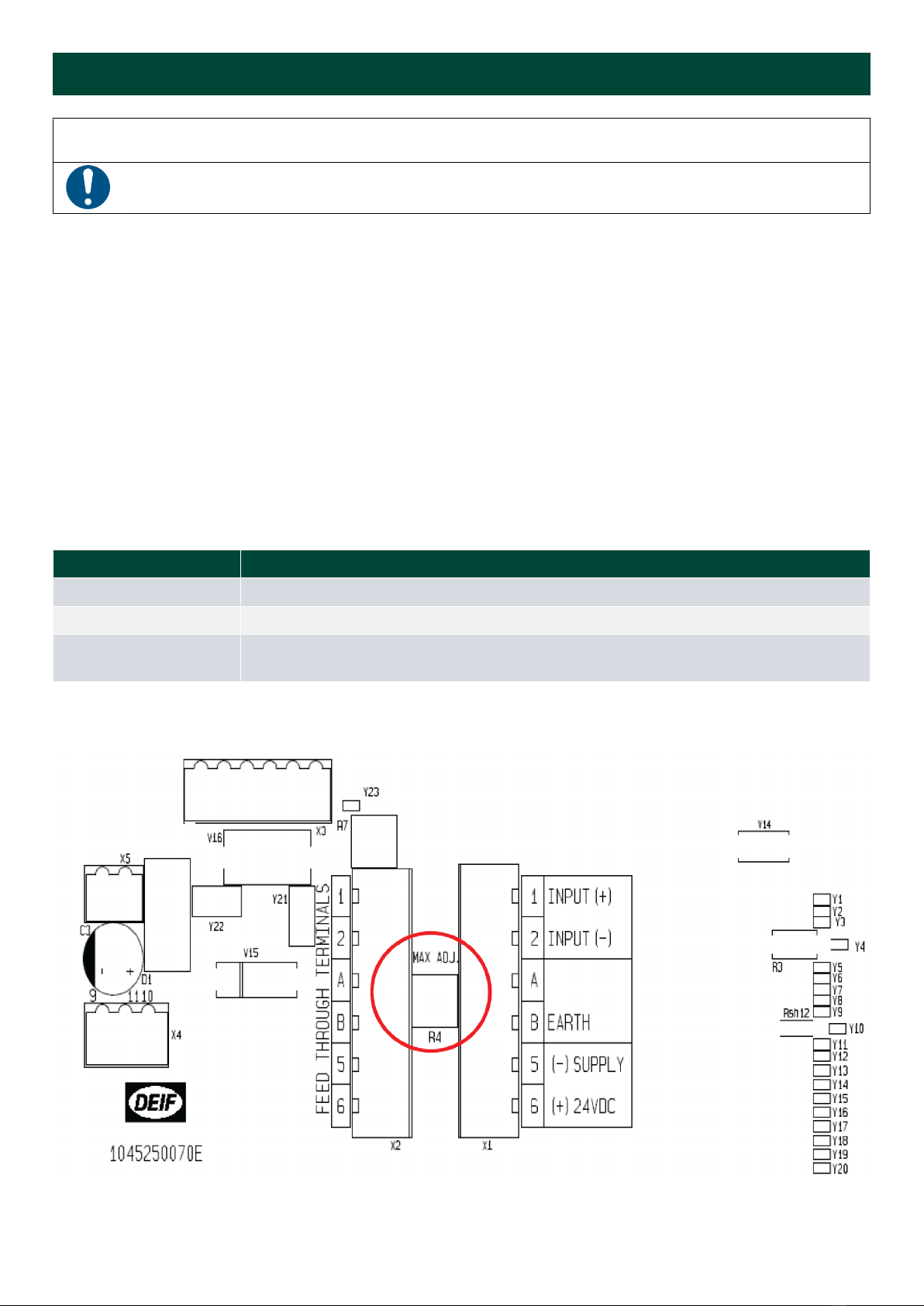
Terminal pos. Supply
5 -
6 + 24 V DC
B EARTH.
This terminal must be connected to the ship's hull.
The potentiometer marked “MAX. ADJ”, located between the two connectors, can be used to make fine adjustments to the
pointer deflection to match the indicator's scaling with the existing installation.
QUICK START GUIDE 4189350057C UK Page 3 of 4

3. General
Accuracy
This is a special version of the BRW-2 with additional circuits to simulate BRW-1 operation. This means it does not meet the
standard specified accuracy of Class 0.5.
BRW-2 Replacement meets accuracy Class 1.0.
Future replacement
For future replacement, it is not necessary to replace the entire BRW-2 indicator. You may only need to replace the XL192
indicator part (the top part of the product).
NOTE When replacing the built-in XL 192 indicator, the measuring range is either 0 mA to 1 mA or -1 mA to + 1 mA. See
the type label on the XL 192 indicator.
QUICK START GUIDE 4189350057C UK Page 4 of 4
Other manuals for BRW-2
2
This manual suits for next models
1
Table of contents
Other Deif Measuring Instrument manuals


Popular Measuring Instrument manuals by other brands


C.E.DI.T.
C.E.DI.T. EFI.06 product manual

Airflow
Airflow Silent+ Mini Orange instruction manual

GARANT
GARANT HCT user guide

Kistler
Kistler 9317C instruction manual

In-situ
In-situ Aqua TROLL 600 Operator's manual

elsner elektronik
elsner elektronik TH PF Series Technical specifications and installation instructions


