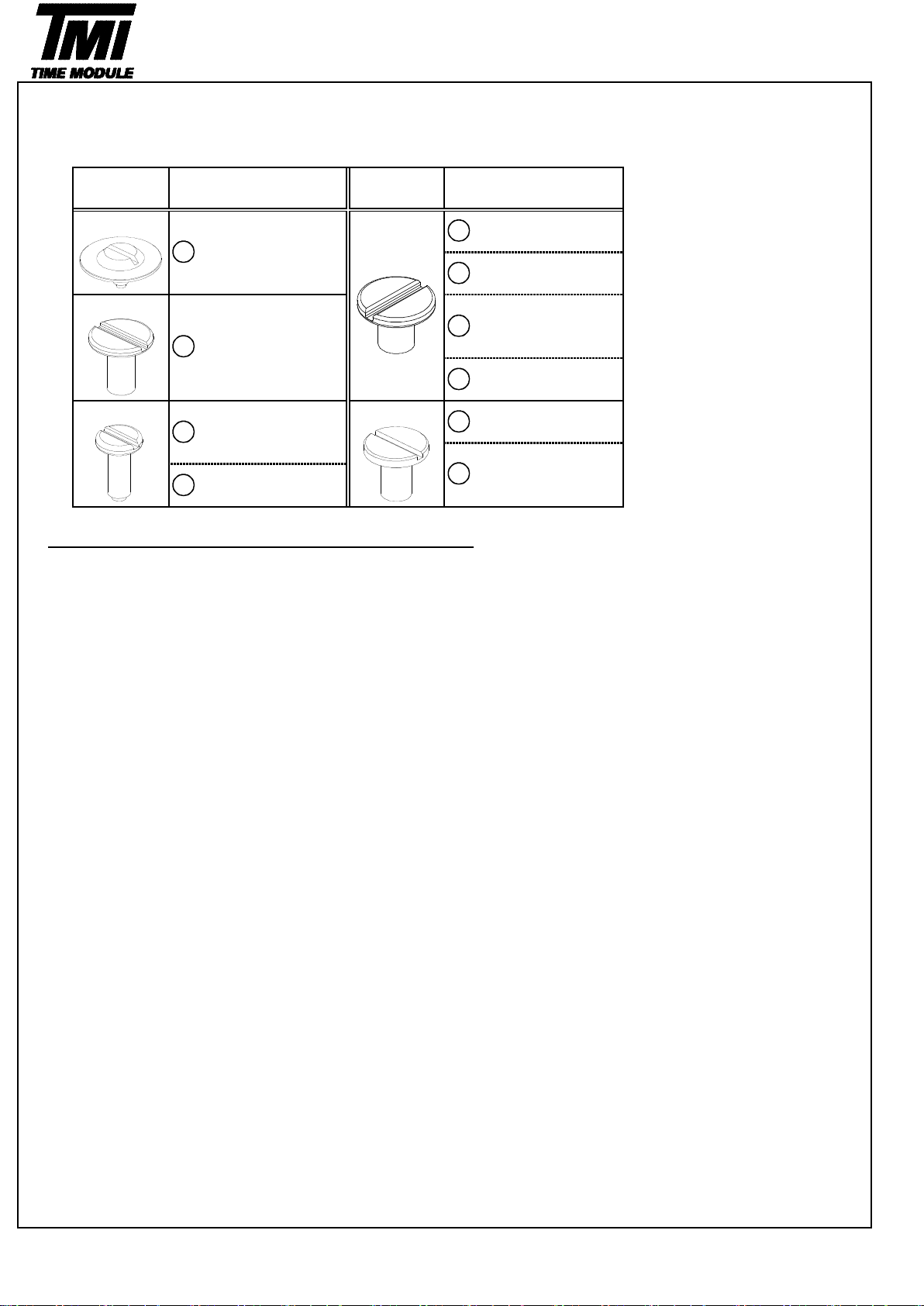
SII TMI NE20 Installer manual

SII Products
TECHNICAL GUIDE
&
PARTS CATALOGUE
Cal.NE20
AUTOMATIC MECHANICAL
Revised on: 28. May. 2012

[SPECI ICATION]
Free Manual winding
Date setting Day setting
Difference is under 45 seconds within max value and min value.
* Measurement should be done within 10 60 minutes after fully wound up.
* Direction of 4 positions.
(1) 12 o'clock up (2) 9 o'clock up (3) 6 o'clock up (4) 3 o'clock up
Isochronisms
(24h-0h)
-10 +20 seconds per day.
* Direction of position. : Dial up
* Difference of static accuracy of 24h and 0h
Duration time
More than 45 hours Mainspring after fully wound up.
* Posture to confirmation : Dial up
Normal position
Right rotation
-15 +25 seconds per day
* Measurement should be done within 10 60 minutes after fully wound up.
* All measurements are made without the calendar in function.
Measurement
position
Direction of 3 positions. (1) Dial up (2) 9 o'clock up (3) 6 o'clock up
Lift angle
52 deg.
First click
Jewels
29 jewels
20 seconds
* Equipment to be used : Witschi WATCH EXPERT
Posture
difference
Manual winding
Automatic winding with ball bearing
Stop second device
Day-date correction
<< Movements >>
・Fully wounded up by turning the crown min 55 times.
・Fully wounded up by turning the ratchet wheel screw 8 times.
<< Complete Watch >>
A winding machine is needed to wind up the mainspring.
Full wind up conditions
・Rotary speed : 30 rpm
・Operating time: 60 minutes
Crown
position
Left rotation
Casing diameter
Ф27.00mm
Total height
Winding the mainspring
Frequency
28,800 vibrations per hour
Accuracy
Static accuracy
6.15 mm
PARTS CATALOGUE / TECHNICAL GUIDE
Cal.NE20
Version-01
Cal. No.
Measurement
time
Time indication
Basic function
3 Hands ( Hour , Minute , Second )
Day-date calendar hands
Power reserve hand
Ф27.40mm
SII Products
1
Item
NE20
Second click Hand setting Hand setting
Movement
Movement
size
Outside diameter

Type of oil Oil quantity mark
Moebius 9010 NORMAL QUANTITY
MO-4 SUFFICIENT QUANTITY
MO-3
0012 201
Auxiliary train wheel bridge screw
1019 002
Power reserve wheel 0126 030
Auxiliary train wheel bridge
1010 267
Barrel arbor pinion
0817 047 1026 002
Intermediate power reserve wheel Planetary reduction wheel
1009 004
Second sun wheel
1001 025
Sun and planet unit
1009 003
Sun wheel
Refer to the page8 for the
oiling position.
(Back side)
2
SII Products
Version-02
Cal.NE20
PARTS CATALOGUE
58
58 →1
1
3
2
5
Disassembling procedures Figs.
Reassembling procedures Figs.
1→
*2
9
6
8
7
4
*1
*1
*2

Type of oil
Oil quantity mark
Moebius 9010
MO-4
NORMAL QUANTITY
MO-3 SUFFICIENT QUANTITY
0898 001
Day driving wheel
0802 036 0970 003
Date driving wheel Day star
0970 002 0873 017
Date star Day jumper
0810 017 1001 029
Date jumper Day-date corrector setting unit
0012 201 0737 021
Auxiliary main plate screw Date corrector setting wheel
0102 030
Auxiliary main plate
0261 183
Lower shock absorbing spring Minute wheel and pinion
0273 029
Lower shock absorbing Hour wheel
cap jewel
Lower hole jewel frame
for shock-absorber
0225 413
Cannon pinion
Main plate
(Back side)
12
16
3
SII Products
20
21
Version-03
Cal.NE20
PARTS CATALOGUE
11
(Back side)
17
18
58
19
10
13
52-1
52-2
52-3
14
15
*1 *1
*2
*2
*3
*3

Type of oil
Oil quantity mark
Moebius 9010
MO-4
NORMAL QUANTITY
MO-3 SUFFICIENT QUANTITY
0509 414
Oscillating weight with ball bearing
*Refer to the page10 for
assembling position
0012 354
0012 420 0191 025
Balance bridge screw Automatic train wheel bridge
0171 349 0514 010
Balance cock
0012 919
Ratchet wheel screw
0285 051
Ratchet wheel
0012 354
Pallet bridge screw
0161 310
0310 048 Pallet bridge
Balance complete
with stud 0301 310
Pallet fork
Upper shock absorbing spring
Upper hole jewel frame for shock-absorber
29-4
Version-04
Cal.NE20
PARTS CATALOGUE
4
SII Products
27
30
31
22
23
28 24
29 25
Upper shock absorbing cap jewel
Automatic train wheel bridge screw
29-1
32
29-2
Second reduction wheel and pinion
29-3
26
*1
*3
*2
*2
whole tooth
*1
*3

Type of oil
Oil quantity mark
Moebius 9010
MO-4
NORMAL QUANTITY
MO-3 SUFFICIENT QUANTITY
0012 420
0511 010
First reduction wheel and arbor
0363 156
Ratchet sliding wheel spring
0831 077
Pawl lever Cap jewelled spring
Cap jewel
0114 387
Barrel and train wheel bridge
*Refer to the page8 for the
oiling position.
0836 002 0436 164
Reduction wheel holder Lower plate for barrel and train
wheel bridge
0012 354
0241 216 Lower plate for barrel and train
Fourth wheel and pinion wheel bridge screw
0231 070
Third wheel and pinion
0012 354
Center wheel bridge screw
0122 302
Center wheel bridge
39
43
38
35
5
SII Products
44
42
37
41
36 40
Version-04
Cal.NE20
PARTS CATALOGUE
33
34-2
34
Barrel and train wheel bridge screw
34-1
*Refer to the page10 for assembling
*1 *1

Type of oil
Oil quantity mark
Moebius 9010
MO-4
NORMAL QUANTITY
MO-3 SUFFICIENT QUANTITY
0224 085
Center wheel and pinion
0381 004
Click
0201 074
Barrel complete with mainspring
0251 310
Escape wheel and pinion 0012 168
Yoke spring screw
0388 177
Yoke spring
0384 183
Yoke
0383 183
0601 310 Setting lever
Balance stop lever
0282 183
Clutch wheel
0283 020
Winding pinion
0962 164
Day-date corrector setting
transmission wheel A
0351 200
Winding stem
Main plate
56
57
50
Version-04
Cal.NE20
PARTS CATALOGUE
45
46
47
48
51
52
58
6
SII Products
49
53
54
55
*1
*2
*2
*1

Remarks
●
●●
●
List of screws
*All parts code are subject to change without notice.
28
Lower plate for
barrel and train
wheel bridge screw
Parts No
43
Name
0012 354
0012 919 Center wheel bridge
screw
23
Automatic train wheel
bridge screw (×2)
Version-02
Cal.NE20
PARTS CATALOGUE
30
Parts NoName
Pallet bridge screw
(×2)
39
7
SII Products
Auxiliary main plate
screw
18
1Auxiliary train wheel
bridge screw (×4)
Balance bridge
screw
Barrel and train
wheel bridge screw
(×3)
0012 420 0012 201
Ratchet wheel screw26
0012 168
33
Yoke spring screw
(×2)
49

Oiling position
(1) Barrel and train wheel bridge (back side)
Notes:
*1
After oiling, set Lower plate for barrel and train wheel bridge and screw.
Lower plate for barrel and train wheel bridge screw
Lower plate for barrel and train wheel bridge
(2) Planet unit
Second sun wheel
Notes:
*2 Oil to between the arbor pinion and the gear.
sun and planet unit
Sun wheel
Version-03
Cal.NE20
TECHNICAL GUIDE
9
52
First reduction wheel and arbor
●
7
8
39
40
8
SII Products
*1
*2

1.Setting position (Refer at the time of disassembling and reassembling)
・To Date / Day driving wheels setting position
Notes: Set a tooth of Day / Date stars toward the notch of Day / Date driving wheels.
Day star
Day driving wheel
Date star
Date driving wheel
・Position confirmation by the movement
Day driving wheel confirmation window Day star
Day driving wheel
Auxiliary train wheel bridge
Date star
Date driving wheel confirmation window Date driving wheel
*The correct positions of Day / Date stars and Day / Date driving wheels should be confirmed from the
confirmation window at the same time.
2.Method of identifying day jumper and date jumper
*There is no bend at the spring.
*There is a bend at the spring.
Day driving wheel
confirmation window
Date driving wheel
confirmation window
9
SII Products
Day jumper
Day-date jumper
Date jumper
Version-01
Cal.NE20
TECHNICAL GUIDE
13
11
10
14
Part
expansion
Side
view

3.Rachet sliding wheel spring setting
Ratchet sliding wheel spring
Barrel and train wheel bridge
4.Setting position of oscillating weight
・Before assembling oscillating weight.
Match the center of the oscillating weight and winding stem.
Set the hole of first reduction wheel gear on the imaginary line
toward the balance bridge guide pin.
Balance bridge guide pin First reduction wheel gear
5.To remove the winding stem
1) Set the winding stem to normal position.
2) Pull out the winding stem, while pushing "A"
Setting lever
Winding stem
54
10
SII Products
Version-02
Cal.NE20
TECHNICAL GUIDE
35
34
52
A
Enlarged
view

6.Disassembling / assembling of the irst reduction wheel
First reduction wheel and arbor
Reduction wheel holder
Barrel and train wheel bridge (back side)
7.Accuracy adjustment
Regulator
Regulator pin
Stud support
Note:
・
・・
・
Regulator @ Time adjustment
・
・・
・
Stud support @ Beat error adjustment
・
・・
・
Regulator pin @ Gap adjustment of balance spring and regulator pin
11
SII Products
Version-03
Cal.NE20
TECHNICAL GUIDE
<< Disassembling >> << Assembling >>
Anticlockwise rotation No clockwise rotation
38
36
34
(+) side
(-) side

8.To wind up the mainspring
<<Movement>>
Screwdriver winding Turn the ratchet wheel screw 8 times clockwise.
Screwdriver
Ratchet wheel screw
Ratchet wheel
9.How to attach hands
Static weighting
Place the movement directly on a flat metal plate or something similar to attach the hands.
We recommend the use of movement holder to attach hands.
For hands attachment, please use a special equipment.
When the movement receives a strong shock, it may be damaged.
<<Note: Power reserve hand setting>>
(1)The mainspring should be fully wounded up before setting power reserve hand.
(2)Set power reserve hand at the fully wound up position of the dial graduation.
Setting position of power reserve hand
[ Image design ]
10.Accuracy measurement condition
Static Accuracy : -15 +25 seconds per day
Measurement Conditions
1) Measurement should be done within 10 60 minutes after fully wound up.
2) Lift angle : 52 deg.
3) Measurement position : (1) Dial up (2) 9 o'clock up (3) 6 o'clock up
4) Minimum measurement Time : 20 seconds
5) Stabilizing Time :
Leave the watch for at least 20 seconds to stabilize after you change its measurement position.
Version-02
Cal.NE20
TECHNICAL GUIDE
12
SII Products
The mainspring would be fully wounded up by turning the ratchet wheel screw 8 times clockwise. (Manual winding or Screwdriver)
Manual winding Rotate crown clockwise at normal position by min 55 times. (Equal to ratchet wheel screw 8 times )
[ Manual winding ] [ Screwdriver winding ]
Metal plate

[ NE20 operation manual ]
Hour hand Minute hand
Power reserve hand Crown at normal position
Second click
Second hand
First click
Date hand
Day hand
1.Time setting
1) Pull out the crown to the second click position.
2) Turn the crown to set hour and minute hands.
(Check that AM/PM is set correctly.)
3) Push the crown back into the normal position.
*When time setting is performed in counterclockwise, day and date hands reverses.
Please reset by day-date correction.
2.Day-date hands setting
1) Pull out the crown to the first click position.
2) Turn the crown to left for date setting.
3) Turn the crown to right for day setting.
* Do not set the calendar between 9:00 P.M. and 2:00 A.M. If the setting of the calendar is made during this period,
the day or date will not change to the next day or date. Please set the calendar after changing the time other than
the above period.
4) Push the crown back into the normal position.
3.To wind up the mainspring
a) Manual winding Rotate the crown clockwise at normal position.
Wind turning the ratchet wheel screw 8 times. It will start to move naturally after shaking slightly.
b) To wind up with winding machine.
Full wind up conditions
・Rotary speed : 30 rpm
・Operating time : 60 minutes
13
SII Products
Version-01
Cal.NE20
OPERATION
Table of contents