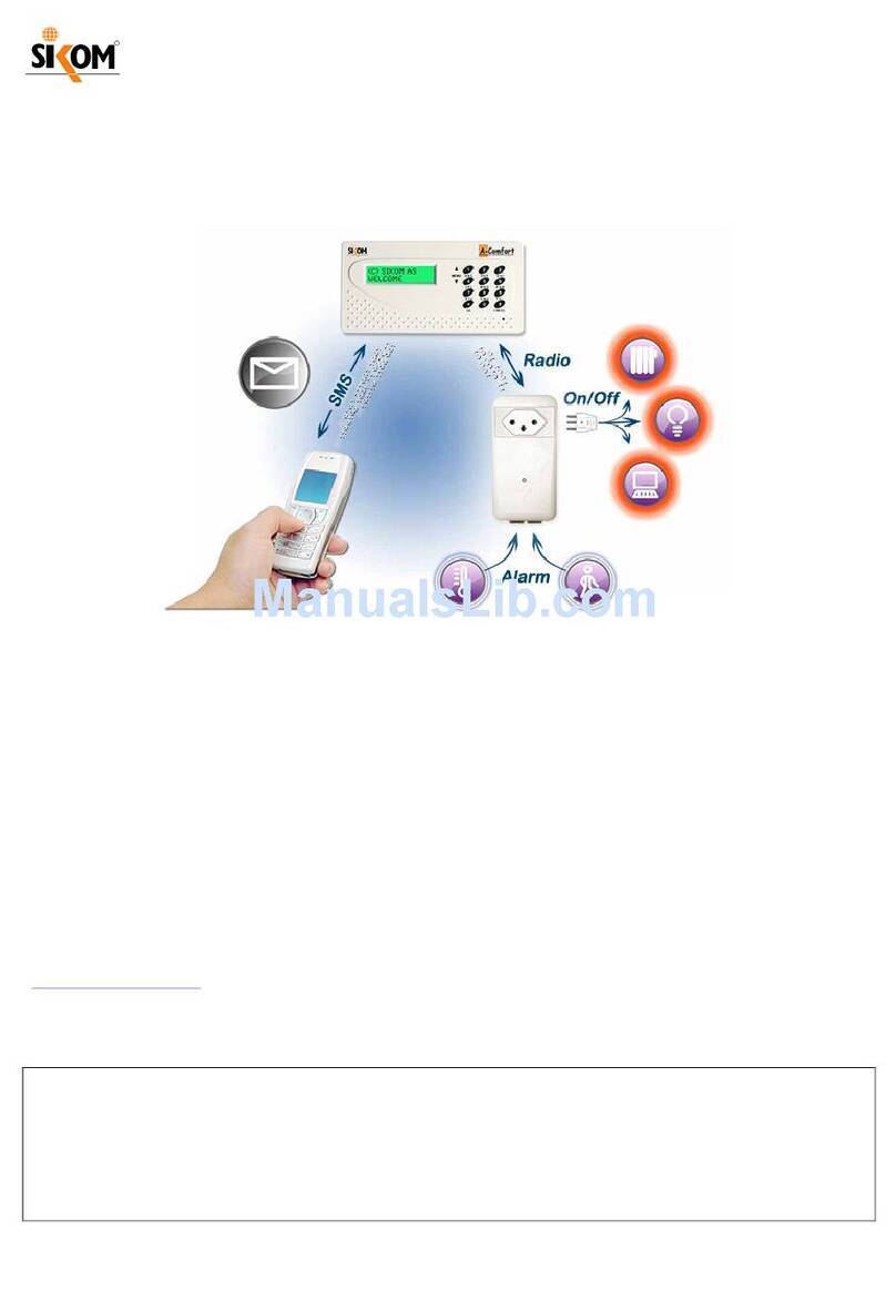
SiKom A-Comfort Operating manual

www.EcoStarter.com 64-309-48_004-Manual-A-Comfort_RevGR1.5-ENG-CH.doc
A
-Comfort
SMS-operated Alarm and Switch Control
User and Installation Manual
User and Installation Manual
Informationen auf Deutsch / Informations en français :
www.EcoStarter.com
Contents: Page:
Introduction: What MUST be done + terms/notions ................................. 2
Chapter 1: Installation ............................................................................ 3
1.1 Preparation of the SIM card ........................................................... 3
1.2 Insertion of the SIM card ................................................................ 3
1.3 Fixing the Unit to the Wall ............................................................. 4
1.4 Connection to the Power Source .................................................... 5
1.5 Antennas ......................................................................................... 5
1.6 Start-up Procedure .......................................................................... 5
1.7 Mobile Network Coverage ............................................................. 6
1.8 Registration of Keyboard, Nodes, Sensors ..................................... 7
Chapter 2: Main Menu (Control via Input Panel) ................................ 10
Chapter 3: Keyboard (On-Site Control) .............................................. 15
3.1 Locally Switch Node On/Off ........................................................ 15
3.2 Locally Turn Alarm On/Off ......................................................... 15
3.3 Battery .......................................................................................... 15
Chapter 4: SMS Control of A-Comfort ............................................... 16
4.1 Alarm on/off ................................................................................. 16
4.2 Control (Switch Nodes On/Off) ................................................... 16
4.3 Change Personal Access Code ..................................................... 17
4.4 Registration of Mobile Phone Numbers ....................................... 17
4.5 Activation/Deactivation of a Number .......................................... 17
4.6 Status Messages ............................................................................ 18
4.7 Info ............................................................................................... 20
4.8 Temperature Surveillance ............................................................. 20
4.9 Thermostatic Control (T-Control) ................................................ 21
Chapter 5: Alarm Functions ................................................................. 22
Chapter 6: Miscellaneous Information ................................................ 24
Chapter 7: Front Panel ......................................................................... 27
Chapter 8: Error Messages ................................................................... 27
Chapter 9: Preconditions and Advice .................................................. 28
Chapter 10: Technical Specifications .................................................... 29
Chapter 11: Warranty ............................................................................ 30
Chapter 12: Recycling Information ....................................................... 30

Page 2 64-309-48_004-Manual-A-Comfort_RevGR1.5-ENG-CH.doc
www.EcoStarter.com
For a complete understanding of the product, and before initiating any connection,
it is important to entirely read through the instructions.
The following MUST be read and done to get started:
Chapter 1 / page 3: Installation and configuration:
- About your SIM card (and inserting it correctly)
- Installation, connection to the power source
- Mobile network coverage
- “Identification” of keyboard, wireless sockets,
temperature sensors, etc.
- Input of mobile phone numbers to which
A-Comfort will send alarm and status messages.
Chapter 4 / page 16: SMS control (for remote control of A-Comfort):
-Turn switches on/off (e.g. for stoves)
-Turn alarm on/off
-Get status message from A-Comfort
During the setup procedure, you will be led through a number of steps that are further
explained in other chapters (e.g., several menus described in Chapter 2, as well as SMS
control in Chapter 4).
Terms and Notions Used in this Manual
Input panel: The keyboard on the A-Comfort central unit.
Keyboard: Small wireless remote control for on-site usage.
Node: Plug-in wireless 230V socket for controlling electric current and
connecting sensors.
Inputs: Inputs 1 and 2 on the underside of the wireless socket (node).
Menu 1.7: (example) Menus are organized hierarchically. The example “Menu 1.7” refers
to Main menu 1, Sub-menu 7.
PIR: “Passive InfraRed Sensor”, usually called
IR sensor
or
motion
detector
.
Registration: Operation by which a wireless accessory or extension is identified
for the first time by the central unit it will depend on.
Temperature surveillance: A function where A-Comfort sends you a message if the
temperature falls down to e.g. 4°C or raises up to e.g. 20°C.
Requires a temperature sensor to be connected to input 1 of your
node.
Thermostatic control
(T-Control): With a temperature sensor connected to input 1 of your node, and a
stove or radiator plugged into the socket, the built-in thermostatic
regulation allows you to choose between comfort temperature and
eco-temperature.
Personal code A 4-digit password (factory-set to
1234)
that A-Comfort requires
in all SMS commands, and in certain commands executed locally.
Not to be confused with the PIN code (of the SIM card), which, in
contrast, has to be deactivated!

64-309-48_004-Manual-A-Comfort_RevGR1.5-ENG-CH.doc Page 3
Swiss edition www.EcoStarter.com
Other frequent options:
•Temperature sensor (usable indoors, and also outdoors, if the tip is sufficiently
protected against humidity).
•Wireless remote control (“Keyboard”) for on-site control of switches and alarms.
•PIR sensor (motion detector) with 4m cable and plug.
•Wall bracket w/2 screws.
•“GR-1” and “GR-3” modules: alternatives to a Node for controlling electric circuits from
the fuse box. To be installed by an electrician.
The following must be done before A-Comfort is ready to use (and before
connecting the central unit to the power source).
Chapter 1.1: Preparation of the SIM Card
To be able to send and receive SMS messages, A-Comfort needs a SIM card. SIM cards
from any mobile phone operator will work, both pre-pay and subscription based.
NB: for pre-pay cards, durability and usage are limited, and usually requires a follow-up.
A-Comfort requires the SIM card PIN code to be deactivated. This has to be done
by temporarily inserting the SIM card into a normal GSM mobile phone in order to turn
off the PIN code of the SIM card. The exact procedure will be described in the manual
of your mobile phone.
Chapter 1.2: Insertion of the SIM Card
NB! A-Comfort must not be connected to the power source; always disconnect it from the
power source when handling the SIM card or when opening the case.
Unscrew the 2 screws on the backside of the central unit, and gently lift off the top
cover. Insert the SIM card into the holder and slide it into position. The card shall be
placed upside down (the gold contact side facing down, and the notch in the lower
right corner). See fig. 1 below.
CHAPTER 1: INSTALLATION
A-Comfort central unit with display
and input panel.
Not pictured above: a GSM antenna
and a radio antenna.
Schuko version Swiss version
”Node”
(Wireless 230V socket)
For controlling stoves, lights, etc.

Page 4 64-309-48_004-Manual-A-Comfort_RevGR1.5-ENG-CH.doc
www.EcoStarter.com
Fig. 1: Insertion slot of the SIM card
After having inserted the SIM card and removed the protective tape from the display, put back
the top cover, and mount the unit onto the wall (on top of the included wall bracket, as explained
in Chapter 1.3 below).
Chapter 1.3: Fixing the Unit to the Wall
Fig. 2: Mounting bracket – for fixing the central unit to the wall
Gently push your A-Comfort into position, onto the two holders, and fasten it with 2 screws (as
in figure 3 below).
Fig. 3: Fastening of A-Comfort
SIM
Screw the wall bracket to the wall (using
the 2 enclosed wood screws) through the
two ”keyholes”. Adjust the bracket to
make it hang straight on the wall, and
then firmly tighten the screws.

64-309-48_004-Manual-A-Comfort_RevGR1.5-ENG-CH.doc Page 5
Swiss edition www.EcoStarter.com
Chapter 1.4: Connection to the Power Source
A-Comfort comes with an already mounted cable and plug. The unit
may
also be mounted
in front of a hidden junction box: disconnect then the 230V cable and remove the central
part of the mounting bracket (this must be performed by a qualified electrician).
Battery backup (optional equipment):
In addition to its 230V power source, A-Comfort may receive a battery backup solution
provided by Sikom. Information on how to connect this option comes with the backup
solution. The connectors may be found by disconnecting the power source, removing the
top cover and turning the printed circuit over.
NB: Main menu 3, sub-menu 8 shall not be activated!
SMS:
With battery backup installed, A-Comfort will send this SMS in the event of power
interruption: Power!
When the power is restored, it will send the SMS message: Power OK!
A-Comfort can also be powered by 12 volts sources
To this end, remove the 230V cable and connect the 12 volts source to the black terminal
strip labelled +12V and GND (ground).
NB: Main menu 3, sub-menu 8 shall be activated for 12V usage, in order to prevent
warnings about power interruptions.
Chapter 1.5: Antennas
The GSM antenna resides on the top of A-Comfort. If the mobile network coverage is
too weak, it may be replaced with an external directional antenna.
The radio antenna is attached to the underside; this is a short, white cable, which MUST
hang straight down. A-Comfort uses the 433.9 MHz radio frequency for communicating
with wireless equipment like nodes and keyboard.
Chapter 1.6: Start-Up Procedure
•Power on the unit (e.g. by inserting the plug into a socket)
The display shows:
Pressing the OK key makes the following appear:
After initiation, the text will scroll in the display, showing information about the product,
such as the software version, GSM status, number of registered wireless peripherals,
etc. This text will usually keep scrolling continuously.
NB!
If no SIM card is inserted, or the PIN code still is active, this message will be displayed:
Initiating GSM
*****
Error, press OK
8: GSM SIM card
Central reg.!
Press OK key.

Page 6 64-309-48_004-Manual-A-Comfort_RevGR1.5-ENG-CH.doc
www.EcoStarter.com
In this case, disconnect the power and verify that the SIM card has been inserted
correctly and/or check if the PIN code still is active (by inserting the card into a mobile
phone and ascertaining that no PIN code is requested when the phone is turned on).
Chapter 1.7: Mobile Network Coverage
Verify the mobile reception conditions with the following steps:
•Press the OK key on the A-Comfort input panel. This text will be
displayed:
•Press the arrow key (4) downwards to main menu 4: GSM Setup
The display will show:
•Press the OK key
You will be asked for your personal code. Key in the 4-digit
access code (factory set to 1234)
•Press the arrow key down to
Sub-menu 3: Signal
•Press the OK key, and one of the following will be displayed:
Signal strength: Good!
•The coverage is satisfactory – or:
Signal strength: Medium!
•The coverage
may
be good enough (conditions do not have to be as good
for SMS messaging as for voice calls). It may help to move the product
to another place in the room, or even to another room with better
coverage (the coverage may also be evaluated by making a standard
phone call, and noting the level on the display of the mobile phone).
Signal strength: Bad!
•Try to move A-Comfort to another place with better coverage. It may be
necessary to use an external antenna; contact your reseller or Sikom AS.
(More on mobile network coverage in Chapter 9).
Return to the main menu with the CANCEL key. This key is also used for
correcting wrong input or if you are unsure of your position in the menu
structure.
NB! The following may appear on the display:
Main menu:
1: Alarm
Main menu:
4: GSM Setup
Error, press OK
2: Timeout!
More than 1 minute has elapsed
since the last keypress. Press OK,
and continue.

64-309-48_004-Manual-A-Comfort_RevGR1.5-ENG-CH.doc Page 7
Swiss edition www.EcoStarter.com
Chapter 1.8: Registration of Keyboard, Nodes, Sensors
A: REGISTRATION OF KEYBOARD
•Press the OK key on the input panel of A-Comfort, and this will show up in the
display:
•Scroll downwards with the arrow key (4) to the following:
•Press the OK key.
(at this point you will be asked for your personal code; key in the 4-digit access
code, which was factory set to 1234).
•Confirm with the OK key.
•You will then receive advice to follow directions for keyboard registration.
FOLLOW THESE STEPS:
•Keep the Sand Akeys of the keyboard depressed together for 4-5 seconds.
The display will shortly show the registration number. Write down this number.
The display will then show:
If not successful, try again by keeping the S and A keys depressed for 4-5 secs.
The light-emitting diode (LED) should flash the colour sequence green-green-red
several times to indicate success.
•Press the OK key (on the A-Comfort central unit)
•Return to the main menu with the CANCEL key (input panel of A-Comfort).
Remove the protective film from the keyboard before use.
Read more on how to use the local keyboard in Chapter 3.
B: REGISTRATION OF ”NODES” (Wireless Sockets)
•Go to the Main menu (by pressing the OK key)
•Scroll with the arrow key down to Main menu 8: Node
•Press the OK key, and you will see this in the display:
•Press the OK key, and the display will show:
Main menu:
1: Alarm
Main menu:
7: Keyboard
New keyboard OK!
Node menu
1: New node
Keyboard menu:
1: New keyboard

Page 8 64-309-48_004-Manual-A-Comfort_RevGR1.5-ENG-CH.doc
www.EcoStarter.com
•The node may be plugged into any socket.
•The display will shortly show the registration number. Write down this number.
•The central unit will then display:
If no more nodes are to be registered, just press the CANCEL key.
NB! Registered keyboard and nodes are given sequential numbers by the central unit (00,
01, 02, etc.). It is important to write down what number each node is given, and where
each node is placed. We recommend fixing on each node a small sticker showing the
number it received at registration.
If several nodes are to be registered, repeat the mentioned procedure:
•Plug the node into a power socket
•Follow the rest of the procedure, and write down the new registration number
Sample numbering of registered equipment:
Keyboard: 00
1st registered node: 01
2nd registered node: 02 etc.
•Place the nodes nearby the stoves, lamps, etc, which are to be controlled by
A-Comfort, and write down their numbers and where they are located (e.g.: node
01 = bedroom, node 02 = living room, node 03 = annexe, etc).
You may also name the nodes, as explained in Chapter 6.3.
Why is it important to write down the number (00, 01, etc) of all equipment?
When controlling stoves etc. via SMS, you have to tell which node (more precisely: which
number) to switch on or off. The same applies to requests for status messages. Similarly,
these numbers have to be known when controlling nodes locally with the keyboard. Read
more on this in Chapter 4.
C: CONNECTION OF MOTION DETECTORS, SMOKE
DETECTORS, TEMPERATURE SENSORS, etc:
•Pull the node out of the wall socket
•Plug a temperature sensor (for indoor temperature) into input 1
•Plug a motion or smoke detector into input 2
New node OK!
Press OK key.
Follow node reg. procedure!

64-309-48_004-Manual-A-Comfort_RevGR1.5-ENG-CH.doc Page 9
Swiss edition www.EcoStarter.com
If no temperature sensor is needed, input 1 may instead be used with other
equipment, like a smoke or motion detector. See Chapter 6.2 for information on
how to connect the cables.
•Put the node back into the wall socket. A-Comfort automatically registers
connected equipment (only if acquired from Sikom AS for A-Comfort).
To preserve their precision, temperature sensors should be laid out so as to avoid
electrical interference, e.g. from 230 V cables or floor heating. Also, protect
them from excessive humidity.
D: INPUT OF MOBILE PHONE NUMBERS TO WHICH
A-COMFORT SHALL SEND MESSAGES:
Explanation:
For A-Comfort to be able to send SMS alarm messages (such as in the event of
an activated intrusion or smoke detector), it must know the mobile phone numbers
to which the messages shall be sent (i.e., your mobile phone number, plus up to 8
other mobile phone numbers).
•Press the OK key on the input panel of A-Comfort, to make this text appear:
•Press the arrow key (4) to scroll down to the following:
•Press the OK key.
(at this point you may be asked for your personal code; key in the 4-digit access
code, which was factory set to 1234)
•Confirm with the OK key.
•Confirm that you want the number to be stored at position 1 with the OK key
•Key in your mobile phone number, and press OK
•The display confirms that the number has been stored
•The CANCEL key will lead you back to the main menu
For more information related to programming and activating/deactivating mobile phone
numbers, we refer to Chapter 2, Main menu 4: GSM Setup.
Main menu:
1: Alarm
Main menu:
4: GSM Setup
GSM:
1: Number
Choose position
1:
Enter number

Page 10 64-309-48_004-Manual-A-Comfort_RevGR1.5-ENG-CH.doc
www.EcoStarter.com
A-Comfort has its own display and input panel where configuration and control can take place
manually. Some menu commands require the user to input a personal code in order to modify
settings. This code is factory set to 1234, but you should set your own (see Chapter 2, Main
menu 1.3 below). Of course, do remember your new code!
To enter the main menu, always do the following:
•Press the OK key.
•Choose a menu from the main menu (browse the menu with the up/down arrow keys).
•Press the OK key to select an entry in the main menu, and browse further through the
sub-menus with the arrow keys.
•Press the OK key to select a sub-menu, and so on.
•Press CANCEL to go back.
Chapter 2.1: Menu 1: Alarm (read more about alarm functions in Chapter 5)
This menu offers the following commands, to be selected with the OK key (except for
Sub-menu 1.7, these options are also available by SMS):
Sub-menu: 1: Alarm Off - or
Sub-menu: 2: Alarm On
Sub-menu: 3: Change code (i.e. the access code)
Pressing OK leads to the request:
Enter new code !
Key in the new 4-digit code and confirm with OK
Take note of your new access code
IMPORTANT! It will no longer be possible to send SMS commands if you lose or
forget your access code, because A-Comfort will refuse to
execute them! Should you forget your code, you will
only
be able
to set a new code by resetting the central unit. For security
reasons, this can
only
be done physically on the central unit.
Sub-menu 4: Tempsurv. On
Explanation:
This menu option requires a temperature sensor to be connected
to input 1 of given node.
You may e.g. want to receive an SMS message if the temperature
of a room falls down to +4°C, or if it raises up above +20°C.
To this end, press OK, then input Low (the lower temperature
limit) and High (the higher temperature limit):
Use key “1” for “+” (plus) and key “4” for “–” (minus):
E.g.: Low +04 High +20 (temperatures are always given with two
digits) shall be typed like this: ”104 120”
Press OK to proceed:
CHAPTER 2: MAIN MENU (Control via Input Panel)

64-309-48_004-Manual-A-Comfort_RevGR1.5-ENG-CH.doc Page 11
Swiss edition www.EcoStarter.com
Choose node (the chosen values are still displayed)
Press up/down arrow keys, and the unit will propose available
nodes in turn.
Confirm chosen node with OK to turn temperature surveillance
ON for that node. An alarm message (SMS) will then be sent if
any limit is exceeded.
NB! Alarm messages will not be sent if
Master Alarm
is
deactivated (see sub-menu 6 and Chapter 5: Alarm Functions).
Sub-menu 5: Tempsurv. Off
Press OK, and the unit will ask: Choose node.
Select the node with up/down arrow keys.
Confirm with OK, and temperature surveillance will be turned OFF
for the chosen node.
Sub-menu 6: Master alarm (toggle (de)activation of all alarms; cf. Chapter 5)
Press OK, and the unit will ask: Master Alarm Deactivate?
or Master Alarm Activate? depending on the current mode.
Press OK again to confirm the toggling of Master Alarm.
Sub-menu 7: Alarm Timeout (delay until an intrusion alarm is sent off)
Press OK, and the unit will ask: Enter delay
Input the desired number of seconds (as a 2-digits value).
Chapter 2.2: Menu 2: Control (Turning Switches On / Off)
Explanation of available choices:
A-Comfort allows you to manage nodes and similar equipment, such as GR-1
and GR-3, as remote switches. You may choose to either keep them in a
manual control mode, i.e. to remotely switch appliances on/off yourself, or
set them in a thermostatic regulation (
T-Control
) mode, i.e. to let the
node manage its own on/off switching as required to reach the desired
high (
Comfort
) or low (
Eco
) temperature. The T-Control mode requires a
temperature sensor and a heating appliance to be connected to the
relevant node.
You can choose between “Turn On/Comfort” (to switch on explicitly, when
in manual mode, or to reach the comfort temperature, when in T-Control
mode) and “Turn Off/Eco” (to switch off explicitly, when in manual mode,
or to reach the eco-temperature, when in T-Control mode). For the T-
Control mode, you must first input the desired
eco-temperature
(i.e. the
lowest temperature during your absence), and
comfort temperature
(i.e.
the one you want at your arrival).
NB! If no temperature sensor is connected to the node, thermostatic
regulation cannot work, and Sub-menus 1 and 2 will function in manual
mode (remote manual on/off switching). If you do have a temperature
sensor, but
only
want to switch equipment on and off yourself, then you do
not need to specify any comfort or eco-temperature. Any connected
temperature sensor will then only be used to obtain the room temperature
when you request a status message (see Chapter 4.6: Status Message).
Sub-menu: 1: Turn On/Comf
Press OK, and the unit will ask ”Choose node”.
Press up/down arrow keys to browse the nodes.
Press OK at the appropriate node number to switch that node On;
the unit will confirm with message "Node On!".

Page 12 64-309-48_004-Manual-A-Comfort_RevGR1.5-ENG-CH.doc
www.EcoStarter.com
Sub-menu 2: Turn Off/Eco
Press OK, and the unit will ask ”Choose node”.
Press up/down arrow keys to browse the nodes.
Press OK at the appropriate node number to switch that node Off;
the unit will confirm with message ”Node Off!”.
Sub-menu 3: T-Control On. Thermostatic control presupposes that a
temperature sensor is connected to the node on input 1.
Press OK, and the unit will display:
Eco Comfort
To set +4°C as eco-temperature, and +20°C as comfort
temperature, do as follows, using key “1” for “+” (plus) and key “4”
for “–” (minus), and always writing temperatures with two digits.
E.g.: Eco +04 Comfort +20 shall be typed in a sequence like this:
”104 120”.
Confirm with OK.
”Choose node” appears in the display.
Press up/down arrow keys to browse through numbers 00, 01, and
so on. Confirm selection of node with OK, and temperature
regulation (or thermostatic control function) will be ON.
Sub-menu 4: T-Control Off
Select the node with up/down arrow keys, and confirm with OK
(comfort and eco-temperatures will no longer be active; any
stoves may only be explicitly switched on / off).
Chapter 2.3: Menu 3: Configuration
Explanation: This menu enables changing various settings of the central unit itself, as
well as obtaining information about registered peripherals. Among available commands,
swapping over registration numbers can be performed here.
Sub-menu: 1: Sound off
Turns off keypress beeps.
Sub-menu 2: Sound on
Turns on keypress beeps.
Sub-menu 3: Volume
Press OK, and use up/down arrow keys to adjust among the 16
available levels. A scale shows the level.
Sub-menu 4: Show equipment
Press OK to view the number of registered peripherals (nodes,
keyboard, etc). Press the down arrow key to see the number
assigned to each piece of registered equipment.
Sub-menu 5: Swap equipment
Swaps over the registration number between two peripherals, e.g.
between one node and one keyboard. This is a handy function, if
you want to arrange node numbers to start from 00 and upwards.
Type in the (two digit) numbers of the devices that are to swap
positions.
Sub-menu 6: Software Ver(sion)
Sub-menu 7: Central info
Sub-menu 8: 12V Power
Activate this only if A-Comfort is powered by a 12 volts source.

64-309-48_004-Manual-A-Comfort_RevGR1.5-ENG-CH.doc Page 13
Swiss edition www.EcoStarter.com
Chapter 2.4: Menu 4: GSM Setup
Explanation: For A-Comfort to be able to send SMS alarm messages (such as in the
event of an activated intrusion or smoke detector), you must beforehand
input the mobile phone numbers to which the messages shall be sent (i.e.,
your mobile phone number, plus up to 8 other mobile phone numbers), as in
Sub-menu 1.
In Sub-menu 2 you can browse through registered phone numbers, and
optionally activate / deactivate them (if the corresponding person does
not want such messages any more).
Sub-menu 3 provides information about the mobile network coverage
where your A-Comfort is located.
Sub-menu: 1: Numbers
This is a menu for storing up to 9 mobile phone numbers to which
messages shall be sent. Select the desired number position with
the arrow keys, and press OK; the unit will then ask you to “Enter
number”. Key in the phone number and press OK; the unit will
confirm with “Stored!”
The “+” (plus) prefix in international phone numbers is typed in
using the “*” (star) key as first digit.
Sub-menu 2: Active numbers
A-Comfort will first show which number positions are active (e.g.
1 2 3 4). Use arrow keys to browse to the number you want
(de)activated. Press OK to toggle its state. All active numbers will
receive alarm messages from there on.
Sub-menu 3: Signal
Shows the GSM signal strength (good, medium, bad). Find more
information on this in Chapter 1.7: Mobile Network Coverage.
Sub-menu 4: Info
Shows information on the embedded GSM phone (may be of
interest only to the manufacturer).
Chapter 2.5: Menu 5: Detector
This menu only concerns detectors/sensors that are not directly plugged into a node (use
Main menu 8 for detectors plugged into a node). More information comes with the actual
detector.
Sub-menu 1: New detector
Sub-menu 2: Del. detector
Sub-menu 3: List
Information on connection and registration is included with the actual detector.
Chapter 2.6: Menu 6: Siren
External siren may be acquired from Sikom AS.
Sub-menu 1: New siren
Sub-menu 2: Delete siren
Sub-menu 3: List
Information on connection and registration procedure is included with the siren.

Page 14 64-309-48_004-Manual-A-Comfort_RevGR1.5-ENG-CH.doc
www.EcoStarter.com
Chapter 2.7: Menu 7: Keyboard
Sub-menu 1: New keyboard
See Chapter 1.8A on keyboard registration.
Sub-menu 2: Show info
This menu may be used to find the number assigned to a keyboard.
Follow instructions on the display.
Sub-menu 3: Del. keyboard
Select appropriate keyboard by browsing up/down with arrow
keys. It can then be removed from A-Comfort.
Sub-menu 4: List
Shows information on registered keyboards.
Chapter 2.8: Menu 8: Node (Wireless Socket)
Sub-menu 1: New node
See Chapter 1.8B on node registration.
Sub-menu 2: Delete node
Select relevant node by browsing up/down with arrow keys.
It can then be removed from A-Comfort.
Sub-menu 3: List
A-Comfort will show the number of registered nodes. Select a
node using the arrow keys, and press OK. Browse further to obtain
the status of the chosen node: connected sensors, name,
and temperatures.
Sub-menu 4: Name node
Select relevant node with the arrow keys, and confirm with OK.
The unit will then ask you to type in a name (max 10 characters);
see alphabet given in Chapter 6.3.
Press OK when the node is named.
Sub-menu 5: Ping
Performs a communication test with a chosen node, to help
determining if the radio network provides sufficient coverage
from the central unit to the given node.

64-309-48_004-Manual-A-Comfort_RevGR1.5-ENG-CH.doc Page 15
Swiss edition www.EcoStarter.com
Chapter 3.1: Locally Switch Node On/Off
The keyboard is for locally controlling the nodes, and for (de)activating the alarm.
To control a node, press Sfollowed by the 2-digit node number.
The node will then switch itself off if it is on, and on if it is off.
Note that if the thermostatic control function is active, this will
toggle between comfort and eco-temperature.
Example:
S01 Switch on/off node 01
S02 Switch on/off node 02
Chapter 3.2: Locally Turn Alarm On/Off
By pressing A, followed by the personal code, one can turn the alarm on and off, as well
as check if it is on or off. More precisely, first press A, then wait for the keyboard LED
to flash green or red according to this convention:
green = inactive alarm “open entry”
red = active alarm “restricted or no entry”
If it blinks alternatively red/green, the radio coverage between the central unit and the
keyboard may be insufficient (try to move closer to the central unit), or the keyboard
may not be registered (registration takes place by pressing Sand Asimultaneously as
the central unit is in registration mode; see Chapters 1.8A and 2.7 for details).
Example:
Press A.
Wait until the blinking red or green light (indicating the current alarm status).
Type the personal code (4 digits).
Wait again until the blinking red or green light (indicating the new alarm status).
Chapter 3.3: Battery
The keyboard contains 2 batteries of type MN9100 LR1 Duracell.
These are standard N size 1.5V batteries. To change them, disassemble the keyboard by
releasing the screws on the backside.
CHAPTER 3: KEYBOARD (On-Site Control)

Page 16 64-309-48_004-Manual-A-Comfort_RevGR1.5-ENG-CH.doc
www.EcoStarter.com
The following commands are to be used for SMS (text messaging) control of A-Comfort:
IMPORTANT!
To send a text message to A-Comfort, always do the following:
•Open the messaging application of your mobile phone, and create a new SMS
message, and:
•First type the access code (factory-set code: 1234)
•Type your command(s) as described below
•Send the message to the mobile phone number of (the SIM card in) your A-Comfort
The commands will be composed of a key letter (A,R,C,O,N,S,I,T,L) followed by parameters, the
most frequent being parameter 1 for ON and 0 for OFF. All examples are surrounded by
quotation marks (" ") that must not be included in the message.
Chapter 4.1: ALARM (Turn Alarm On / Off)
Command: A
0 = OFF (alarm is partially deactivated)
1 = ON (alarm is activated)
2 = Master Alarm deactivated (all alarms/detectors are deactivated)
Example (do not include the quotation marks):
”1234 A0” = you send a message to turn the alarm OFF (leaving
on
the detectors that
ensure your safety even when you are there: fire/smoke, gaz, etc).
”1234 A1” = you send a message to turn the alarm ON.
”1234 A2” = you send a message to deactivate the Master Alarm.
If you are unsure if the alarm is on or off, just send an SMS to query the central unit, as
explained in Chapter 4.7 below.
Chapter 4.2: CONTROL (Switch Nodes On / Off)
Command: R
The two first digits indicate the node number (e.g. 00); always use 2 digits!
Third digit:
0 = OFF (or request eco-temperature in T-control mode)
1 = ON (or request comfort temperature in T-control mode)
Example (do not include the quotation marks):
”1234 R011” = you want node 01 to switch itself ON
”1234 R010” = you want node 01 to switch itself OFF
”1234 R250” = you want node 25 to switch itself OFF
To obtain a simultaneous confirmation (status message) that node 01 really switched
itself on (as in the first example), write the following SMS:
”1234 R011 S01” =
you want node 01 to switch itself on, and then you want a status
message in reply by SMS (S=Status message) from that node (see Chapter 4.6 below).
CHAPTER 4: SMS CONTROL OF A-COMFORT
Remote Control of Central Unit

64-309-48_004-Manual-A-Comfort_RevGR1.5-ENG-CH.doc Page 17
Swiss edition www.EcoStarter.com
Remember to write the Rand Scommands in that order, otherwise A-Comfort will send
the status message before applying the control command.
SMS: (Sample reply from A-Comfort )
From:”Chalet”
No. 01 Name.----------
Out. On
Tempsurveil. Off
Input 1. +08c 2. Not connected!
Explanation:
From: The name you gave A-Comfort in the contact list on your mobile phone
No. 01 (number of the node this status message is about)
Name.----- (with letters instead of dashes if you name the node, as in Chapter 6.3)
Out. On (the node delivers power to the equipment plugged into its socket)
Tempsurveil. Off (temperature surveillance is off)
Input 1.+08c 2.Not connected (the temperature sensor connected to input 1 senses
8°C, and nothing is connected to input 2).
Chapter 4.3: CHANGE ACCESS CODE (from the factory-set to a personal code)
Command: C
4 digits (composing your new code)
Example:
”1234 C4321” = you change the access code from 1234 to 4321
”1234 C9999” = you change the access code from 1234 to 9999
NB! Remember the new code, and use this code each time you send a message to A-Comfort, or
control it on-site with the keyboard, or interact through the input panel of the central unit.
Chapter 4.4: REGISTRATION OF MOBILE PHONE NUMBERS
Command: N
First digit = position where the mobile phone number will be stored (of 9 available)
The rest: the number of the mobile phone, possibly with an international prefix
Terminate with # (hash/sharp/number sign)
Example:
”1234 N1+4748054555#” = store the number +47 48054555 at position 1
”1234 N348054555#” = store the number 48054555 at position 3
The number is automatically activated when stored.
See also the Ocommand for (de)activating a number.
Chapter 4.5: ACTIVATION/DEACTIVATION OF A NUMBER
Handles already registered mobile phone numbers (for reception of any alarm messages).
Command: O
First digit: 0 = off, 1 = on
Second digit: Position (from 1 to 9) of the phone number to be (de)activated.

Page 18 64-309-48_004-Manual-A-Comfort_RevGR1.5-ENG-CH.doc
www.EcoStarter.com
Example:
”1234 O01” = deactivate number at position 1 (you don't want it to receive alarms).
”1234 O11” = activate number at position 1 (No. 1 shall receive alarm messages again).
”1234 O17” = activate number at position 7.
Active numbers will receive alarm messages whenever detectors are set off, or if a
temperature limit is exceeded when temperature surveillance is activated. Deactivated
phone numbers will not receive any messages.
NB: Usual status messages (see Chapter 4.6 below) are only returned to the one who
requested the status message (A-Comfort answers to the mobile phone number that sent
the request).
Chapter 4.6: STATUS MESSAGE (request information from your A-Comfort)
Command: S
2 first digits = Node number
Example:
”1234 S00” = you request the status of node No. 00 *)
”1234 S12” = you request the status of node No. 12
”1234 S00S01S02” = you request the status of node No. 00, 01 and 02
A-Comfort will send 1 message for each requested node.
The third above example will generate three SMS messages.
SMS:
*) Sample status message (answer from the unit):
From: ”Belvedere” (i.e. the name/phone number of your A-Comfort)
No. 00 Name.-----
Out. On
Tempsurveil. Off
Input 1. +12C
2. Not connected!
Explanations:
From: Mobile phone number (or corresponding residence name in your contact list)
No. 00 Name.-----
Out. On (The node is switched ON, because you previously either switched it on
manually, or sent an SMS to switch it ON)
Tempsurveil. Off (Temperature surveillance is off, see Chapter 2.1, Main menu 2.4)
Input 1. +12C (The temperature sensor connected to input 1 senses +12°C)
2. Not connected! (No detector or temperature sensor connected to input 2)
SAMPLE STATUS MESSAGES:
•If you have set your Eco- and Comfort temperatures, then these values will appear in the
message.
E.g.:
Comfort. (T-control is active in
Comfort
position)
Eco. +04 (Temperature chosen as lower limit when in the
Eco/Off
position)
Comfort. +20 (Upper limit when in the
Comfort/On
position).

64-309-48_004-Manual-A-Comfort_RevGR1.5-ENG-CH.doc Page 19
Swiss edition www.EcoStarter.com
Tempsurveil. Off
Input 1. +12C (Temperature at sensor connected to input 1 of node is +12°C)
2. Not connected! (No detector or temperature sensor connected to input 2 of node)
•If you have turned temperature surveillance ON, you will also be able to read the chosen
temperature limits for the given node in the status message, as in this example:
Tempsurveil. On
Hi. +20 Low. +04
•If Temperature surveillance is activated, you will receive an SMS message such as this as
soon as one of the chosen limits is exceeded:
01 Alarm ……… (Warning about exceeded temperature limit)
1. TempLo (The lower temperature is exceeded)
Alternatively:
01 Alarm ………
1. TempHi (The higher temperature is exceeded)
Remember that whenever you receive an alarm message about an exceeded temperature
limit, you must reactivate the "Temperature surveillance ON", if you still want to receive
such warnings. See Chapter 4.8 "Temperature Surveillance".
Hint: The chosen temperature values may be modified, and may be different from node to
node.
•If a motion detector is connected to input 2 of node number 00, and this detector goes off,
you will then receive this SMS from A-Comfort:
No.00 Alarm. ………
2. PIR
•If a smoke detector is connected to input 2 of a node, and this detector goes off, you will
receive the following SMS:
No.00 Alarm. ………
2. FIRE
Explanation: This is an alarm message from node number 00. Smoke detector at input 2
activated the alarm. Any dots in the message may be replaced by given node names (See
Chapter 6.3).
•Should you request a status message from an unregistered node number, your A-Comfort will
reply along the following:
No.03 Name.-----
5.No answer (see Chapter 8.5)
This message will also be sent in case of bad radio coverage between given node and
A-Comfort. Try again.

Page 20 64-309-48_004-Manual-A-Comfort_RevGR1.5-ENG-CH.doc
www.EcoStarter.com
Chapter 4.7: INFO (about stored phone numbers and active alarms)
Command: I
One digit: the requested kind of information message
1 = request overview of numbers stored at positions 1-9.
2 = request list of active numbers.
3 = request alarm status.
Example 1:
”1234 I1” = you request info message No. 1 (about stored phone numbers)
You will shortly receive an SMS from A-Comfort as follows:
Entered numbers. 1.0480545555 2. 3. 4. 5. 6. 7. 8. 9.
signifying that only position 1 contains a number, and none of the other
positions do.
Example 2:
”1234 I2” = you request info message No. 2 (about active phone numbers)
You will shortly receive an SMS similar to the following:
Active numbers. 1.active 2.active 3.active 4.5.6.7.8.9
Example 3:
”1234 I3” = you request info message No. 3 (about (de)activated alarms).
You will shortly receive one of the three following SMS messages:
1) Central. All alarms activated. 230V OK! - or
2) Central. Alarm inactive. (PIR and magnet deactivated) 230V OK! - or
3) Central. All alarms off. MasterAlarm deactivated. 230V OK!
You can send as a single SMS message to A-Comfort a compound request to switch nodes on/off,
to obtain status from various nodes, as well as an info message from the central unit.
E.g.: 1234 R001 S00 I3 (to request switching node 00 on, receiving a status message about
node 00, as well as obtaining an info message about alarm status).
Chapter 4.8: TEMPERATURE SURVEILLANCE
Temperature surveillance can be (de)activated via the input panel of A-Comfort, using Main menu
1.4 (as described on page 10 of this manual), or via SMS.
Remember that, after having received an SMS either with "Temp.Hi" or "Temp.Lo", you have to
reactivate temperature surveillance, as well as to re-specify the temperatures, for the given
node (otherwise, you would keep receiving SMS messages each time the temperature hits the
chosen upper or lower limit).
Command: T
First 2 digits: Node number (e.g., 02)
Third digit: 0 (to deactivate temperature surveillance) or
1 (to activate temperature surveillance; MUST be
followed by a lower and an upper temperature limit)
Example 1:
”1234 T021+04+24” = you turn temperature surveillance ON (for node No. 02)
with a lower limit at +4°C and an upper limit at +24°C.
Other manuals for A-Comfort
1
Table of contents
Other SiKom Security System manuals
Popular Security System manuals by other brands
Honeywell
Honeywell Friedland GlobalGuard operating manual

Cisco
Cisco PIX 525 datasheet

AV Costar
AV Costar ConteraIP MicroDome Duo LX installation manual
OneSpan
OneSpan Digipass FIDO Touch user guide

Yale
Yale HSA3400 Installation, programming, operating
heddier electronic
heddier electronic Human Detector Flex instruction manual
Monacor
Monacor DVT-440SET instruction manual

Bunker Hill Security
Bunker Hill Security 60565 owner's manual
Inhep Digital Security
Inhep Digital Security IDS 800 Installer manual
E2S
E2S BExBG10D-P instruction manual

NAPCO
NAPCO Magnum Alert-900 Operating & installation instructions
ADEMCO
ADEMCO Vista-20 installation instructions
