Marklin Digital 60906 User manual

60906
D
GB
USA
F
S
NL
DK
www.maerklin.de

2
A
K
Anschluss bei Lokomotiven mit Glühlampen mit Masse über den Lok-Rahmen
Connections on locomotives with light bulbs grounded by means of the locomotive‘s frame
Connexion pour locos avec ampoules à prise de masse via le châssis.
Aansluiting bij locs met gloeilampjes met massa via het locframe

3
Diese Anleitung beschreibt den Einbau und die Einstellmög-
lichkeiten des Decoders 60906. Sofern nicht anders erwähnt,
beziehen sich die Funktionen auf diesen Decoder.
Bestimmungsgemäße Verwendung
Der Decoder 60906 ist zum Umrüsten von Märklin Loko-
motiven mit Trommel- oder Scheibenkollektor-Feldspulen-
Motoren, d.h. der Motor darf für den Feldmagnet keinen
Permanentmagneten eingebaut haben.
Der Decoder wird als Ersatz für den mechanischen
Fahrtrichtungsumschalter, Decoder C80 (6080) oder Delta-
Decoder eingebaut.
Lieferumfang
Decoder mit Kabeln
Halteplatte
Senkschraube
Einbauanleitung
Garantieurkunde
Für den Einbau zusätzlich benötigtes Werkzeug: Schrauben-
dreher, Pinzette und Lötstation für eine Löttemperatur bis max.
30W/400˚C mit dünner Spitze, Elektronik-Lötzinn (Ø 0,5-1 mm),
Entlötlitze oder Entlötsaugpumpe.
Sicherheitshinweise
• ACHTUNG! Funktionsbedingte scharfe Kanten.
• Nicht für Kinder unter 15 Jahren.
• Verkabelungs- und Montagearbeiten nur im spannungs-
losen Zustand ausführen. Bei Nichtbeachtung kann es zu
gefährlichen Körperströmen und damit zu Verletzungen
führen.
• Decoder nur mit der zulässigen Spannung (siehe tech-
nische Daten) betreiben.
Beim Umgang mit dem Lötkolben besteht die Gefahr
von Hautverbrennungen.
Technische Daten
• Maße (L x B) 35 x 20,4 mm
• Dauerlast am Motorausgang ≤1,6 A
• Belastung der Lichtausgänge ≤1,4 A
• Belastung AUX 1 – AUX 2 je ≤1,4 A
• Belastung AUX + Licht (Summe) ≤1,4 A
• Max. Ges.-Belastung (Summe) ≤1,6 A
• Max. Spannung ≤40 V
• Kurzschluss und Überlastschutz an den Ausgängen Licht
vorne (LV), Licht hinten (LH), AUX 1 – AUX 2 und an den
Motorausgängen.

4
Funktionen
• Multiprotokollfähig (mfx, fx (MM), DCC und AC/DC).
• Automatische System-Erkennung.
• Anfahr- und Bremsverzögerung können getrennt vonei-
nander eingestellt werden.
• Programming on Main (PoM), diese Programmierung
muss vom Steuergerät unterstützt werden. Beachten Sie
hierzu die Bedienungsanleitung ihres Steuergerätes.
• Einstellbarer Rangiergang
• Brems- /Signalhalteabschnitt-Erkennung im Digitalbetrieb
• Der Decoder 60906 verfügt über keine Motorregelung.
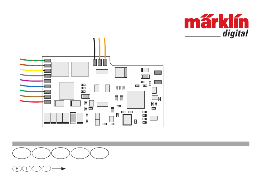
• Verwendete Kabel-Farben nach Märklin-Standard
Der Decoder ist voll updatefähig. Voraussetzung hierfür
ist ein entsprechendes Steuergerät (Central Station 60213
– 60215, Software-Version 4.2.8, 60216 / 60226, Software-
Version 1.4.0).
Die Einstell- und Digitalfunktionen sind nur im Digitalbetrieb
anwendbar. Es stehen jedoch nicht in allen Protokollen die
gleichen Möglichkeiten zur Verfügung.
Hinweis: Im Analogbetrieb (DC) kann bei Lokomotiven bei
denen die Stirnbeleuchtung auf Masse geschaltet ist, bei
Vorwärtsfahrt das vordere Licht nicht leuchten (systembe-
dingt).
Decoder-Einbau
Vor dem Einbau ist die Lokomotive auf einwandfreie mecha-
nische und elektrische Funktion zu prüfen. Gegebenenfalls
muss die Lokomotive vor dem Umbau repariert werden. Für
Schäden durch nicht fachgerechte Arbeiten können wir
keine Garantie gewähren.
• Lok nach Angaben der Bedienungsanleitung öffnen
• mechanischen Fahrtrichtungsumschalter aus der Lok
ausbauen. Die Kabelverbindungen am Motor lösen.
• Die dem Decoder beiliegende Halteplatte an dem Pfosten
anschrauben, an dem der Fahrtrichtungsumschalter
befestigt war. Zum Schutz des Decoders empfehlen wir,
die Schraube mit einem Isolierband abzudecken.
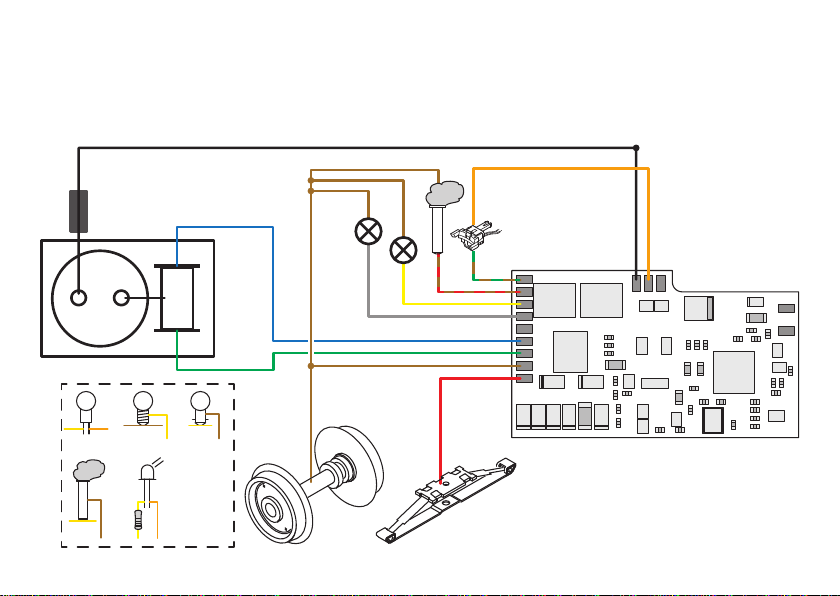
• Die Kabel des Decoders soweit benötigt entsprechend
den Schaltbildern auf Seite 2 oder Seite 39 anlöten.
Hinweis: Die orangen Anschlüsse sind gleichwertig.
Verbraucher, die gegen Masse geschaltet sind (z.B. Rauch)
müssen immer gegen „Braun“ angeschlossen werden
(Masserückführung über den Rahmen / Chassis).
Verbraucher, die nicht gegen Masse angeschlossen sind
(z.B. Telex) dürfen nicht gegen „Braun“ sondern nur gegen
„Orange“ angeschlossen werden.
Das Violette Kabel dient als „Elektronik-Masse“, z.B. für
einen Pufferkondensator.
• Den Decoder in die Halteplatte einklipsen.
• Prüfen, ob alle Kabelverbindungen stabil sind und dass
keine ungewollten Verbindungen bestehen (Kurzschluss).
Achten Sie darauf, dass sich bei Fahrbetrieb keine Kurz-
schlüsse einstellen können.
• Lok in Betrieb nehmen und prüfen, evtl. Fehler beheben.
Wenn die Fahrtrichtung der Lok nicht der Fahrtrichtungen
des Steuergeräts entsprechen reicht es, das grüne und
das blaue Kabel am Motor zu tauschen.
• Lok wieder zusammenbauen.

5
Hinweis: Beachten Sie, dass nicht alle Funktionen in allen
Digital-Protokollen möglich sind. Unter mfx und DCC können
einige Einstellungen von Funktionen, welche im Analog-
Betrieb wirksam sein sollen, vorgenommen werden.
Brems-/Signalhalteabschnitt mfx, fx (MM), DCC
Die Bremsmodule legen im wesentlichen eine Gleichspan-
nung an das Gleis. Erkennt der Decoder eine solche Gleich-
spannung am Gleis, bremst er mit der eingestellten Verzöge-
rung ab. Erkennt der Decoder wieder ein Digital-Protokoll,
beschleunigt er auf die eingestellte Geschwindigkeit.
Soll das automatische Erkennen der Bremsstrecken ange-
wandt werden, wird empfohlen, den DC-Betrieb auszuschal-
ten (siehe CV Beschreibung).
mfx-Protokoll
Adressierung
• Keine Adresse erforderlich, jeder Decoder erhält eine
einmalige und eindeutige Kennung (UID).
• Der Decoder meldet sich an einer Central Station oder
Mobile Station mit seiner UID automatisch an.
Programmierung
• Die Eigenschaften können über die grafische Oberfläche
der Central Station bzw. teilweise auch mit der Mobile
Station programmiert werden.
• Es können alle Configuration Variablen (CV) mehrfach
gelesen und programmiert werden.
• Die Programmierung kann entweder auf dem Haupt- oder
dem Programmiergleis erfolgen.
Multiprotokollbetrieb
Analogbetrieb
Der Decoder kann auch auf analogen Anlagen oder Gleisab-
schnitten betrieben werden. Der Decoder erkennt die analo-
ge Wechsel- oder Gleichspannung (AC/DC) automatisch und
passt sich der Gleisspannung an. Es sind alle Funktionen,
die unter mfx oder DCC für den Analogbetrieb eingestellt
wurden aktiv (siehe Digitalbetrieb).
Digitalbetrieb
Dieser Multiprotokoll-Decoder kann unter folgenden Digital-
Protokollen eingesetzt werden: mfx, DCC, fx (MM),
Das Digital-Protokoll mit den meisten Möglichkeiten ist das
höchstwertige Digital-Protokoll. Die Reihenfolge der Digital-
Protokolle ist in der Wertung fallend:
Priorität 1: mfx
Priorität 2: DCC
Priorität 3: fx (MM)
Hinweis: Digital-Protokolle können sich gegenseitig beein-
flussen. Für einen störungsfreien Betrieb empfehlen wir,
nicht benötigte Digital-Protokolle mit CV 50 zu deaktivieren.
Deaktivieren Sie, sofern dies Ihre Zentrale unterstützt, auch
dort die nicht benötigten Digital-Protokolle.
Werden zwei oder mehrere Digital-Protokolle am Gleis
erkannt, übernimmt der Decoder automatisch das höchst-
wertige Digital-Protokoll, z.B. mfx/DCC, somit wird das
mfx-Digital-Protokoll vom Decoder übernommen (siehe
vorherige Tabelle).

6
Programmierung
• Die Eigenschaften können über die Configuration Varia-
blen (CV) mehrfach geändert werden.
• Die CVs können mehrfach gelesen und programmiert
werden (Programmierung auf dem Programmiergleis).
• Die CVs können beliebig programmiert werden (Program-
mierung auf dem Hauptgleis PoM). PoM ist nur bei den in
der CV-Tabelle gekennzeichneten CV möglich. Die Pro-
grammierung auf dem Hauptgleis (PoM) muss von Ihrer
Zentrale unterstützt werden (siehe Bedienungsanleitung
ihres Gerätes).
• 14 bzw. 28/126 Fahrstufen einstellbar.
• Automatisches Bremsen in der Bremsstrecke
(CV 27 = Wert 48)
• Weitere Information, siehe CV-Tabelle DCC-Protokoll.
Es wird empfohlen, die Programmierungen grundsätzlich auf
dem Programmiergleis vorzunehmen.
Physikalische Funktionen
Jede dieser Funktionen muss extern an die Platine ange-
schlossen werden. Man spricht daher von physikalischen
Funktionen. Jedem physikalischem Ausgang (AUX / Licht)
kann im Digitalbetrieb ein eigener Modus / Effekt zugeordnet
werden. Dazu stehen für jeden Ausgang drei CVs zur
Verfügung. Es kann für jeden Ausgang immer nur ein Modus
/ Effekt eingestellt werden. Eine ausführliche Tabelle hierzu
finden sie im Internet unter: https://www.maerklin.de/de/
service/technische-informationen/
fx-Protokoll (MM)
Adressierung
• 4 Adressen (eine Hauptadresse und 3 Folgeadressen)
• Adressbereich:
1 – 255 abhängig vom Steuergerät / Zentrale
• Hauptadresse ist manuell programmierbar
• Die Folgeadressen sind ein-, ausschalt- und einstellbar
und sind manuell oder automatisch programmierbar.
Programmierung
• Die Eigenschaften des Decoders können über die Pro-
grammierung der Configuration Variablen (CV) mehrfach
programmiert werden. Das Lesen der CVs ist nicht
möglich.
• 14 bzw. 27 Fahrstufen programmierbar
• Weitere Information, siehe CV-Tabelle fx-Protokoll.
DCC-Protokoll
Adressierung
• Kurze Adresse – Lange Adresse – Traktionsadresse
• Adressbereich: 1 – 127 kurze Adresse, Traktionsadresse
1 – 10.239 lange Adresse
• Jede Adresse ist manuell programmierbar.
• Eine angewandte Traktionsadresse deaktiviert die
Standard-Adresse.

7
Logische Funktionen
Da diese Funktionen lediglich per Software ausgeführt
werden, wird hierfür kein physikalischer Ausgang benötigt.
Deshalb spricht man hier von einer logischen Funktion.
Anfahr-/Bremsverzögerung
• Die Beschleunigungs- und Bremszeit kann getrennt von
einander eingestellt werden.
• Die logische Funktion Abschaltung ABV kann über das
Funktionsmapping auf jede beliebige Funktionstaste
gelegt werden.
Rangiergang (RG)
• Der Rangiergang bewirkt eine Reduzierung der aktuellen
Geschwindigkeit. Dies lässt ein feinfühliges Regeln der
Lokomotive zu. Der Rangiergang kann bei mfx und DCC
über das Funktionsmapping jeder beliebigen Funktions-
taste zugeordnet werden (CV137).
Decoder Funktionen und CV Einstellungen
Nachfolgend finden Sie die Funktionen und die CVs in
Tabellenform aufgeführt. Über diese CVs haben Sie die Mög-
lichkeit eine Vielzahl an Einstellungen und die Belegung der
Funktionstasten zu ändern.
Sie finden die CVs und ihre Anwendungen für die Gleisfor-
mate fx (MM) und DCC in getrennten Tabellen.
Das Gleisformat mfx können Sie komfortabel über das
Display der Central Station 60213/60214/60215/60216/60226
einstellen.
Tabelle für die physikalischen Ausgänge
Modus Effekt
0 aus
1 Dimmer
2 Blinklicht 1
3 Blinklicht 2
4 Blitzlicht
5 doppeltes Blitzlicht
6 Feuerbüchse
7 Rauchgenerator
8 Zoom
9 Mars-Light
10 Gyra-Light
11 Licht nach „Regel 17“ vorwärts
12 Licht nach „Regel 17“ rückwärts
13 Neornöhre
14 Energiesparlampe
15 Soft-Telex

8
Schaltbare Funktionen
STOP mobilestation
systems
15
F0 F4
Spitzensignal function/off Funktion f0 Funktion f0
Rauchgenerator f1 Funktion 1 Funktion 7 Funktion f1 Funktion f1
Telex-Kupplung f2 Funktion 2 Funktion 6 Funktion f2 Funktion f2
Rangiergang f3 Funktion 3 Funktion 1 Funktion f3 Funktion f3
ABV ausschalten f4 Funktion 4 Funktion 4 Funktion f4 Funktion f4
CV Bedeutung Werte Default Bemerkung
1Adresse 1 (Hauptadresse) 1 – 80 78
2Minimalgeschwindigkeit (Vmin) 1 – 80 50
3Anfahrverzögerung (AV) 1 – 80 20
4Bremsverzögerung (BV) 1 – 80 15
5Maximalgeschwindigkeit (Vmax) 1 – 63 59
8Decoder-Reset (Default- oder Werkseinstellung) 8
17 Adresse 3 (2. Folgeadresse) 1 – 80 254
18 Adresse 4 (3. Folgeadresse) 1 – 80 253
CV-Tabelle fx (MM)

9
CV Bedeutung Werte Default Bemerkung
27 Bremsmodus:
Bit 4 Polarität entgegen der Fahrtrichtung
Bit 5 Polarität mit der Fahrtrichtung
0 / 16
0 / 32 48
29
Konfiguration:
Bit 0 Fahrtrichtung umkehren
Bit 1 14 oder 27 Fahrstufen
Bit 2 Analogbetrieb möglich
0/ 1
0 / 2
0 / 4
6
49
Erweiterte Konfiguration Folgeadressierung:
Bit 0 Anzahl der Folgeadressen
Bit 1 Anzahl der Folgeadressen
Bit 2 Folgeadresse automatisch / manuell
0 / 1
0 / 2
0 / 4
5Wert von Bit 0 und Bit 1 addiert ergibt die
Anzahl der Folgeadressen
50
Alternative Formate:
Bit 0 Analog AC
Bit 1 Analog DC
Bit 2 DCC
Bit 3 mfx
0 / 1
0 / 2
0 / 4
0 / 8
15 Hinweis:
fx (MM) kann sich selber nicht deakti-
vieren.
75 Adresse 2 (1. Folgeadresse) 1 – 80 255

10
CV Bedeutung Werte Default Bemerkung
1 Hauptadresse 1 – 127 3 Wenn CV29 / Bit 5 = 0
2PoM Minimalgeschwindigkeit (Vmin) 0 – 255 50
3PoM Anfahrverzögerung (AV) 0 – 255 20
4PoM Bremsverzögerung (BV) 0 – 255 15
5PoM Maximalgeschwindigkeit (Vmax) 0 – 255 240
8 Decoder-Reset (Default- oder Werkseinstellung) 8 131
13PoM Funktionen F1 –F8 bei alternativem Gleissignal 0 – 255 0
14PoM Funktionen FL, F9 –F15 bei alternativem Gleissignal 0 – 255 1
17 Erweiterte Adresse, höherwertige Byte 192 – 231 192 CV29 / Bit 5 = 1
18 Erweiterte Adresse, niederwertige Byte 0 – 255 128
19 Traktionsadresse 0 – 255 0 1 – 127 = Traktionsadresse
+128 = Richtung umpolen bei Traktion
21PoM Funktionen F1 –F8 bei Traktion 0 – 255 0
22PoM Funktionen FL, F9 –F15 bei Traktion 0 – 255 0
27PoM
Bremsmodus:
Bit 4 : DC, Polarität entgegen der Fahrtrichtung
Bit 5 : DC, Polarität mit der Fahrtrichtung
Bit 6 - 7 : immer 0
0 / 16
0 / 32
0
48
29PoM
Bit 0 : Richtungsverhalten der Lok umkehren
Bit 1 : Fahrstufen 14 oder 28/128 wählen
Bit 2 : Analogbetrieb aus-/einschalten
Bit 5 : Kurze / Lange Adresse wählen
0 / 1
0 / 2
0 / 4
0 / 32
6
CV-Tabelle DCC

11
CV Bedeutung Werte Default Bemerkung
50PoM
Alternative Formate:
Bit 0 : Analog AC
Bit 1 : Analog DC
Bit 2 : fx (MM)
Bit 3 : mfx
0 / 1
0 / 2
0 / 4
0 / 8
15 Hinweis:
DCC kann sich selber nicht deaktivieren.
66PoM Vorwärts Trimm 0 – 255 128 CV-Wert dividiert durch 128 ergibt
den Faktor, mit dem die Fahrstufe bei
Vorwärtsfahrt multipliziert wird.
67 –
94PoM Fahrstufentabelle 0 – 255
95PoM Rückwärts Trimm 0 – 255 128 CV-Wert dividiert durch 128 ergibt
den Faktor, mit dem die Fahrstufe bei
Rückwärtsfahrt multipliziert wird.
112PoM
113PoM
114PoM
physikalischer Ausgang: Licht vorne Modus
physikalischer Ausgang: Licht vorne Dimmer
physikalischer Ausgang: Licht vorne Periode
0 – 15
0 – 255
0 – 255
1
255
20 Siehe Tabelle Seite 7
115 –
123PoM physikalischer Ausgang: Licht hinten, Aux 1 bis Aux 2
(jeweils im 3er Block) Siehe Tabelle Seite 7
137PoM Rangiergang 0 – 128 128 128 = 50% Fahrstufe, 64 = 25% Fahrstufe
257PoM
262PoM
267PoM
Funktionszuordnung: Funktion FL vorw.
Funktionszuordnung: Funktion F1 vorw.
Funktionszuordnung: Funktion F2 vorw.
0 – 63
0 – 63
0 – 63
1
4
8Siehe Tabelle Seite 7
357PoM
362PoM
367PoM
Funktionszuordnung: Funktion FL rückw.
Funktionszuordnung: Funktion F1 rückw.
Funktionszuordnung: Funktion F2 rückw.
0 – 63
0 – 63
0 – 63
2
4
8Siehe Tabelle Seite 7

12
englisch
These instructions describe the installation and the setting
options on the 60906 decoder. Unless otherwise indicated,
the functions refer to this decoder.
Intended Use
The 60906 decoder is for upgrading Märklin locomotives
with drum-style or flat commutator field coil motors, i.e. the
motor may not have permanent magnets installed for the
field magnet.
This decoder is installed as a replacement for the mecha-
nical reverse unit, the C80 decoder (6080), or the Delta
decoder.
Contents as Delivered
decoder with wires
mounting plate
countersunk screw
Installation instructions
Warranty card
Tools required for the installation: Screwdriver, tweezers, and
soldering station for a soldering temperature up to maximum
of 30 watts / 400˚C / 752˚F with a thin point, electronics solder
(0.5-1 mm dia.), unsoldering wick or unsoldering vacuum
pump.
Safety Notes
• IMPORTANT! Sharp edges due to function design.
• Not for children under 15 years.
• Wiring and assembly work to be done only in the absence
of voltage. Lack of adherence to this can lead to dan-
gerous body current and thereby to injury.
• Operate decoder only with the permissible voltage (see
technical data).
There is the danger of skin burns when working with
the soldering iron.
Technical Data
• Dimensions (L x W) 35 x 20.4 mm / 1-3/8“ x 13/16“
• Continuous load at motor outputs ≤1.6 amps
• Load at light outputs ≤1.4 amps
• Load AUX 1 – AUX 2 ea. ≤1.4 amps
• Load AUX + light(s) (total) ≤1.4 amps
• Max. load (total) ≤1.6 amps
• Max. voltage ≤40 volts
• Short circuit and overload protection at the outputs Front
Light(s) (LV), Rear Light(s) (LH), AUX 1 – AUX 2 and at the
motor outputs.

13
Functions
• Multi-protocol capable (mfx, fx (MM), DCC, and AC/DC).
• Automatic system recognition.
• Acceleration and braking delay can be set separately
from each other.
• Programming on Main (PoM), this programming must
be supported by the control device. See the operating
instructions for your control device.
• Adjustable switching range
•
Braking / signal stop section recognition in digital operation
• The 60906 decoder does not have any motor control.
• Wire colors used follow the Märklin standard
This decoder can be updated. Requirement for this is an
appropriate control device (Central Station 60213 – 60215,
Software-Version 4.2.8, 60216 / 60226, Software-Version
1.4.0).).
The setting and digital functions can only be used in digital
operation. However not all of the same options are available
in all protocols.
Note: In analog operation (DC), the front headlight(s) cannot
light up (due to system design) in forward operation on loco-
motives on which the headlight(s) are switched to ground.
Decoder Installation
The locomotive must be checked for proper mechanical
and electrical function before installing the decoder. It may
be necessary to have the locomotive repaired before the
installation. We cannot cover the warranty for the decoder
due to damage caused by inappropriate work.
• Open the locomotive according to its operating instructions
• Remove the mechanical reverse unit from the locomotive.
Undo the wire connections at the motor.
• Screw the mounting plate included with the decoder to
the post used to mount the reverse unit. We recommend
covering the screw with insulating tape to protect the
decoder.
• Solder the wires from the decoder to where necessary
following the circuit diagrams on page 2 or page 39.
Note: The orange connections have the same value.
Users that are switched to ground (such as smoke units)
must always be connected to „brown“ (ground return by
means of the frame/chassis).
Users that are not connected to „ground“ (example:
Telex) may not be connected to „Brown“ but rather only to
„Orange“.
The violet wire serves as the „Electronics Ground“, such as
for a buffer condenser.
• Clip the decoder into the mounting plate.
• Check whether all wire connections are solid and that
there are no unwanted connections (short circuit).
Make sure that no short circuits can occur during opera-
tion of the locomotive.
• Place the locomotive into operation and check and if
necessary correct any mistakes. If the direction of travel
for the locomotive does not match the directions on the
controller, all you have to do is swap the green and the
blue wire at the motor.
• Put the locomotive back together.

14
Multi-Protocol Operation
Analog Operation
This decoder can also be operated on analog layouts or
track sections. The decoder recognizes the analog AC or DC
voltage automatically and adapts to the track voltage. All of
the functions are active that were set under mfx or DCC for
analog operation (see Digital Operation).
Digital Operation
This multi-protocol decoder can be used under the following
digital protocols: mfx, DCC, fx (MM).
The digital protocol with the most options is the highest va-
lue digital protocol. Here is the sequence of digital protocols
in descending value:
Priority 1: mfx
Priority 2: DCC
Priority 3: fx (MM)
Note: Digital protocols can mutually influence each other.
For interruption-free operation, we recommend deactivating
unneeded digital protocols with CV 50.
As long as your central controller supports it, deactivate
unneeded digital protocols on it too.
When two or more digital protocols are recognized on the
track, the decoder automatically takes on the highest value
digital protocol, ex. mfx/DCC. The mfx digital protocol is
thereby taken on by the decoder (see previous table).
Note: Please note that not all functions are possible in all
digital protocols. Several settings can be done for functions
under mfx and DCC, which are supposed to be effective in
analog operation.
Braking / Signal Stop Section for mfx, fx (MM), DCC
The essential feature of braking modules is that they put DC
voltage into the track. When the decoder recognizes such
DC voltage in the track, it brakes the locomotive with the
delay that has been set. When the decoder recognizes a
digital protocol again, it accelerates the locomotive to the
speed that has been set.
If automatic recognition of braking sections is to be used, we
recommend turning DC operation off (see CV description).
mfx Protocol
Addressing
• No address required; each decoder receives a unique
and distinct identification (UID).
• The decoder automatically registers itself with its UID on
a Central Station or Mobile Station.
Programming
• The properties can be programmed using the graphic
interface on the Central Station or in part with the Mobile
Station too.
• All Configuration Variables (CV) can be read multiple
times and programmed.
• The programming can be done on either the main or the
programming track.

15
fx Protocol (MM)
Addressing
• 4 addresses (a main address and 3 sequential addresses)
• Address range:
1 – 255 depending on the control device / central unit
• Main address can be programmed manually.
• The sequential addresses can be turned on and off and
can be set. They can also be programmed manually or
automatically.
Programming
• The decoder properties can be programmed multiple
times using the programming of the Configuration Variab-
les (CV). Reading the CVs is not possible.
• 14 or 27 speed levels can be programmed.
• For additional information, see the CV table for the fx
protocol.
DCC Protocol
Addressing
• Short address – long address – m.u. address
• Address range: 1 – 127 short address, m.u. address
1 – 10,239 long address
• Each address can be programmed manually.
• An m.u. address in use deactivates the standard address.
Programming
• The properties can be changed multiple times using the
Configuration Variables (CV).
• The CVs can be read and programmed multiple times
(programming on the programming track).
• The CVs can be programmed as desired (programming
on the main track PoM). PoM is only possible with the
CVs marked in the CV table. Programming on the main
track (PoM) must be supported by your central unit (see
operating instructions for your device).
• 14 and 28/126 speed levels can be set.
• Automatic braking in the braking area
(CV 27 = Value 48)
• For additional information, see the CV table for the DCC
protocol.
We recommend doing the programming on the programming
track.
Physical Functions
Each of these functions must be connected externally to
the circuit board. We are therefore talking about physical
functions. Each physical output (AUX / Light(s)) can have its
own mode / effect assigned to it in digital operation. Three
CVs are available to do this for each output. Only one mode
/ effect can be set at a time for each output. An extensive
table for this can be found on the Internet at:
https://www.maerklin.de/de/service/technische-informati-
onen/

16
Logical Functions
Since these functions are merely carried out by software, a
physical output is not needed for this. We therefore speak
here of a logical function.
Acceleration and Braking Delay
• The acceleration and braking time can be set separately
from each other.
• The ABV logical function shutoff can be assigned to any
function button by means of function mapping.
Switching Range (RG)
• The switching range causes a reduction in the current
speed. This allows a fine touch to the control of the
locomotive. The switching range can be assigned in mfx
and DCC to any function button by means of function
mapping. It must be set (see CV table, page 22 CV 137 and
for mfx in the Central Station menu).
Decoder Functions and CV Settings
In the following, you will find the functions and the CVs
shown in the form of tables. Using these CVs, you have the
option of changing a multitude of settings and the assign-
ment of function buttons.
You will find the CVs and their applications for the track
formats fx (MM) and DCC in separate tables.
You can set the mfx track format easily using the
60213/60214/60215/60216/60226 Central Station display.
Table for the Physical Outputs
Mode Effect
0 Off
1 Dimmer
2 Blinking Light 1
3 Blinking Light 2
4 Flashing Light
5 Double Flashing Light
6 Firebox
7 Smoke Generator
8 Zoom
9 Mars Light
10 Gyro Light
11 Forward Light according to "Rule 17"
12 Reverse Light according to "Rule 17"
13 Neon Lights
14 Energy-Saving Lamp
15 Soft Telex

17
Controllable Functions
STOP mobilestation
systems
15
F0 F4
Headlights function/off Funktion f0 Funktion f0
Smoke generator f1 Function 1 Funktion 7 Funktion f1 Funktion f1
Telex coupler f2 Function 2 Funktion 6 Funktion f2 Funktion f2
Low speed switching range f3 Function 3 Funktion 1 Funktion f3 Funktion f3
ABV, off f4 Function 4 Funktion 1 Funktion f4 Funktion f4
CV Meaning Values Default Note
1Address 1 (main address) 1 – 80 78
2Minimum Speed (Vmin) 1 – 80 50
3Acceleration Delay (AV) 1 – 80 20
4Braking Delay (BV) 1 – 80 15
5Maximum Speed (Vmax) 1 – 63 59
8Decoder Reset (default or factory setting) 8
17 Address 3 (2nd sequential address) 1 – 80 254
18 Address 4 (3rd sequential address) 1 – 80 253
CV Table for fx (MM)

18
CV Meaning Values Default Note
27 Braking Mode:
Bit 4 Polarity against the direction
Bit 5 Polarity with the direction
0 / 16
0 / 32 48
29
Configuration:
Bit 0 Reverse Direction
Bit 1 14 or 27 Speed Levels
Bit 2 Analog Operation Possible
0/ 1
0 / 2
0 / 4
6
49
Advanced Configuration
Sequential Addressing:
Bit 0 Number of Sequential Addresses
Bit 1 Number of Sequential Addresses
Bit 2 Sequential Address automatic / manual
0 / 1
0 / 2
0 / 4
5Value of Bit 0 and Bit 1 added gives the
Number of Sequential Addresses
50
Alternative Formats:
Bit 0 Analog AC
Bit 1 Analog DC
Bit 2 DCC
Bit 3 mfx
0 / 1
0 / 2
0 / 4
0 / 8
15 Note:
fx (MM) cannot deactivate itself.
75 Address 2 (1st sequential address) 1 – 80 255

19
CV Meaning Values Default Note
1 Main Address 1 – 127 3 If CV 29 / Bit 5 = 0
2PoM Minimum Speed (Vmin) 0 – 255 15
3PoM Acceleration Delay (AV) 0 – 255 16
4PoM Braking Delay (BV) 0 – 255 20
5PoM Maximum Speed (Vmax) 0 – 255 240
8 Decoder Reset (default or factory setting) 8 131
13PoM Functions F1 – F8 with alternative Track Signal 0 – 255 0
14PoM Functions FL, F9 – F15 with alternative Track Signal 0 – 255 1
17 Advanced Address, higher value Byte 192 – 231 192 CV29 / Bit 5 = 1
18 Advanced Address, lower value Byte 0 – 255 128
19 M.U. Address 0 – 255 0 1 – 127 = M.U. Address
+128 = Reverse polarity of direction when
m.u. address
21PoM Functions F1 – F8 when M.U. 0 – 255 0
22PoM Functions FL, F9 – F15 when M.U. 0 – 255 0
27PoM
Braking Mode:
Bit 4 : DC, Polarity against the direction
Bit 5 : DC, DC, Polarity with the direction
Bit 6 - 7 : Always 0
0 / 16
0 / 32
0
48
29PoM
Bit 0 : Reversing Locomotive Direction Behavior
Bit 1 : Select Speed Levels 14 or 28/128
Bit 2 : Turn Analog Operation on/off
Bit 5 : Select Short / Long Address
0 / 1
0 / 2
0 / 4
0 / 32
6
CV Table for DCC

20
CV Meaning Values Default Note
50PoM
Alternative Formats:
Bit 0 : Analog AC
Bit 1 : Analog DC
Bit 2 : fx (MM)
Bit 3 : mfx
0 / 1
0 / 2
0 / 4
0 / 8
15 Note:
DCC cannot deactivate itself.
66PoM Forward Trim 0 – 255 128 CV value divided by 128 gives the factor,
with which the speed level is multiplied in
forward running.
67 –
94PoM Speed Level Table 0 – 255
95PoM Reverse Trim 0 – 255 128 CV value divided by 128 gives the factor,
with which the speed level is multiplied in
reverse running.
112PoM
113PoM
114PoM
Physical Output: Front Light(s) Mode
Physical Output: Front Light(s) Dimmer
Physical Output: Front Light(s) Period
0 – 15
0 – 255
0 – 255
1
255
20 See table page 16
115 –
123PoM Physical Output: Rear Light(s), Aux 1 to Aux 2
(each in the 3-way block) See table page 16
137PoM Switching Range 0 – 128 128 128 = 50% Speed Level, 64 = 25% Speed
Level
257PoM
262PoM
267PoM
Function Assignment: Funktion FL vorw.
Function Assignment: Funktion F1 vorw.
Function Assignment: Funktion F2 vorw.
0 – 63
0 – 63
0 – 63
1
4
8See table page 16
357PoM
362PoM
367PoM
Function Assignment: Funktion FL rev.
Function Assignment: Funktion F1 rev.
Function Assignment: Funktion F2 rev.
0 – 63
0 – 63
0 – 63
2
4
8See table page 16
Table of contents
Languages:
Other Marklin Digital Media Converter manuals