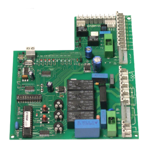
tau K898M User manual

1
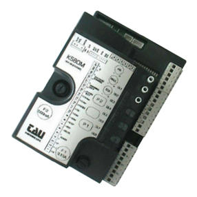
K898M
GUIDA ALL’INSTALLAZIONE
INSTALLATION GUIDE
NOTICE D’INSTALLATION
K898M
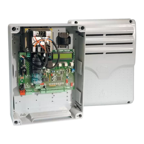
Quadro di comando per uno/due motori monofase 230 Vac
Control panel for one-two single-phase motors 230 Vac
Logique de commande pour un ou deux
moteurs monophasés 230 Vac
Via Enrico Fermi, 43 - 36066 Sandrigo (VI) Italia
Tel +39 0444 750190 - Fax +39 0444 750376
info@tauitalia.com - www.tauitalia.com
IT - Istruzioni originali
D-MNL0K898M 22-05-2012 - Rev.05

2
K898M
D-MNL0K898M
SCHEMA CABLAGGIO K898M / K898M WIRING DIAGRAM

3
K898M
/ SCHÉMA CÂBLAGE K898M

4
K898M
INSTALLAZIONE - INSTALLATION - INSTALLATION
I L’INSTALLAZIONE DELL’APPARECCHIATURA DEVE ESSERE EFFETTUATA
“A REGOLA D’ARTE “ DA PERSONALE QUALIFICATO COME DISPOSTO DALLA LEGGE
46/90.
N.B.: si ricorda l’obbligo di mettere a massa l’impianto nonché di rispettare le normative
sulla sicurezza in vigore in ciascun paese.
LA NON OSSERVANZA DELLE SOPRAELENCATE ISTRUZIONI PUO’ PREGIUDICARE IL
BUON FUNZIONAMENTO DELL’APPARECCHIATURA E CREARE PERICOLO PER LE
PERSONE, PERTANTO LA CASA COSTRUTTRICE” DECLINA OGNI RESPONSABILITA’ PER
EVENTUALI MAL FUNZIONAMENTI E DANNI DOVUTI ALLA LORO INOSSERVANZA.
ATTENZIONE:
- non utilizzare cavi unilari (a conduttore unico), es. quelli citofonici, al ne di evitare
interruzioni sulla linea e falsi contatti;
- non riutilizzare vecchi cavi preesistenti.
F L’INSTALLATON DE L’EQUIPEMENT DOIT ETRE REALISEE “SELON LES
REGLES E L’ART” PAR LE PERSONNEL COMPETENT AYANT LES QUALITES REQUISES
PAR LA LOI 46/90.
N.B.: nous rappelons l’obligation de mettre l’installation à terre et de respecter les normes
de sècuritè en vigeur dans le pays d’installation.
LA NON OBSERVATION DES INSTRUCTIONS POURRAIT COMPROMETTRE LE
BON FONCTIONNEMENT DE L’APPAREILLAGE ET CREER UN DANGER POUR LES
PERSONNES, PAR CONSEQUENT LA MAISON DECLINE TOUTE RESPONSABILITE POUR
D’EVENTUALLES DETERIORATIONS DUES A UNE UTILISATION NON APPROPRIEE OU
NON CONFORME AU MODE D’EMPLOI.
ATTENTION:
- ne pas utiliser les câbles unilaires (à conducteur unique), par exemple ceux des
interphones, an d’éviter les coupures sur la ligne et les faux contacts;
- ne pas réutiliser les anciens câbles préexistants.
GB THE EQUIPMENT MUST BE INSTALLED “EXPERTLY” BY QUALIFIED
PERSONNEL AS REQUIRED BY LAW 46/90.
N.B.: It is compulsory to earth the system and to observe the safety regulations that are
in force in each country.
IFTHESEABOVEINSTRUCTIONARE NOT FOLLOWED IT COULD PREJUDICE THE PROPER
WORKING ORDER OF THE EQUIPMENT AND CREATE HAZARDOUS SITUATIONS FOR
PEOPLE. FOR THIS REASON THE “MANUFACTURER” DECLINES ALL RESPONSABILITY
FOR ANY MALFUNCTIONING AND DAMAGES THUS RESULTING.
ATTENTION:
- do not use single cables (with one single wire), ex. telephone cables, in order to avoid
breakdowns of the line and false contacts;
- do not re-use old pre-existing cables.

5
K898M
INDICE
CONTENTS
INDEX
Pag. 6-7 Italiano
Pag. 8-9 Français
Pag. 10-11 English
Pag. 12 Dichiarazione di conformità / Declaration de coformité / Declaration of
conformity
Pag. 14-16 Garanzia / Garantie / Guarantee

6
K898M
Italiano
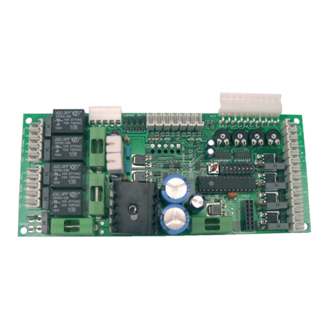
• LOGICACONMICROPROCESSORE
• LEDDIAUTODIAGNOSI
• PROTEZIONEINGRESSOLINEACONFUSIBILE
• LIMITATOREDICOPPIAELETTRONICOINCORPORATO
• CONTROLLOELETTRONICOSPUNTODILAVORO
• CIRCUITOLAMPEGGIOINCORPORATO
• CONNETTOREPERSCHEDARICEVENTE
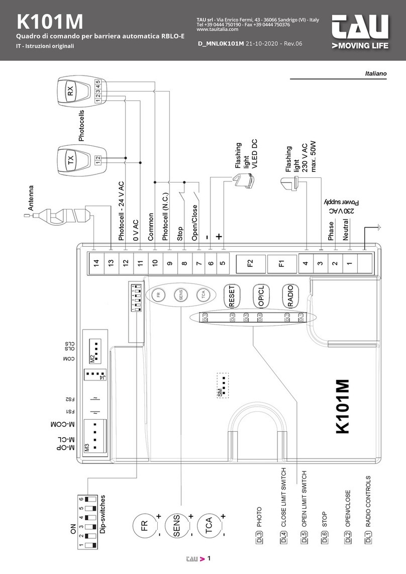
COLLEGAMENTI ALLA MORSETTIERA
1-2-3 uscita motore; 1 = fase apertura; 2 = comune; 3 = fase chiusura
4-5-6 uscita motore aggiunto; 4 = fase chiusura; 5 = comune; 6 = fase apetura
7-8 alimentazione 230 Vac 50/60 Hz.
9-10 uscita lampeggiante 230Vac
11-12 uscita luce di cortesia ausiliaria 230 Vac
13-18 ingresso pulsante Apre/Chiude (contatto Normalmente Aperto): per le modalità d’uso
vedi le funzioni del dip switch nr. 2-3; 18 = Comune
14-18 pulsante Stop contatto NC (Normalmente Chiuso). Dopo l’arresto, l’apparecchiatura
riparte aprendo e soltanto dopo un comando del pulsante di marcia o della
radiotrasmittente. 18 = Comune
15-18 ingresso Finecorsa di apertura (contatto Normalmente Chiuso); 18 = Comune
16-17 ingresso Finecorsa di chiusura (contatto Normalmente Chiuso); 18 = Comune
17-18 Ingresso bordo sensibile (costa meccanica) o altri dispositivi di protezione quali ad
esempio le fotocellule (contatto N C); 18 = Comune
19-20 uscita 24 V ac per alimentazione dispositivi di sicurezza e/o altro (fotocellule, coste
meccaniche, relè per luci, etc).
21-22 uscita 2° canale radio
Nota: per il collegamento di altri dispositivi al 2° canale radio, quali accensione
luci, comando pompe o carichi importanti, utilizzare un relè ausiliario di po-
tenza con portata adeguata ai dispositivi da collegare, altrimenti si potrebbero
avere malfunzionamenti dovuti a disturbi indotti.
23-24 ingresso Antenna radio: 23 = calza, 24 = centrale.
REGOLAZIONE LOGICHE DEL TRIMMER
TL Trimmer di regolazione tempo di lavoro (5-120 sec), ovvero tempo che il basculante
impiega per compiere un’intera manovra. Il suo conteggio inizia ad ogni impulso
di comando. E’ consigliabile una regolazione di qualche secondo superiore al
necessario.

7
K898M
TCA Trimmer di regolazione del tempo di pausa (5-120 sec), ovvero tempo nel quale il
basculante rimane fermo in apertura a TCA abilitato. Il conteggio inizia al termine del
tempodilavoroinaperturaoalraggiungimentodelnecorsadiapertura.Siinterrompe
all’arrivo di un comando manuale di chiusura e si disinserisce temporaneamente a un
comando di stop
RCM Selettore a scatti per regolazione della frizione motore, tarabile su 4 diversi livelli di
coppia. Si consiglia la regolazione partendo da un valore minimo ed incrementando se
nonsufcienteadaprireilportone.Siapplicacosìlaminimacoppiapermovimentare
il portone ed un eventuale urto contro cose e/o persone risulta provocare il minor
danno.
REGOLAZIONE LOGICHE DEI DIP-SWITCH
N°1 OFF:la chiusura necessita di un comando
ON: ad apertura completata, la chiusura del cancello è automatica trascorso un tempo
impostato sul trimmer T.C.A.
N°2 OFF: ad automazione funzionante, una sequenza di comandi di apertura/chiusura
induce il cancello ad una APERTURA-STOP-CHIUSURA-STOP-APERTURA-
STOP (funzione passo passo).
ON: nelle stesse condizioni, la stessa sequenza di comandi induce il cancello ad una
APERTURA-CHIUSURA-APERTURA-CHIUSURA, ect.
N°3 OFF: (no reverse) il cancello ignora i comandi di chiusura durante l’apertura
ON: il cancello si comporta come stabilito dal dip switch nr.2
N°4 OFF: è possibile collegare al pulsante apre-chiude un timer/orologio che possa gestire
l’apertura e la chiusura a fasce orarie (Ingresso stabile).
ON: il pulsante apre e chiude si comporta normalmente.
N°5 OFF: conseguentemente allo start la porta inizierà a muoversi immediatamente.
ON: pre-lampeggio inserito, ad ogni inizio manovra il lampeggiante funzionerà per
circa 3 secondi prima che la porta inizi a muoversi.
ATTENZIONE:
Per ogni coppia di morsetti facenti capo ad un contatto NC non utilizzato, bisogna effettuare un
cortocircuito per poter garantire il normale funzionamento della scheda.
L’impianto di massa a terra del portone deve essere conforme alle norme vigenti. La Casa
Costruttrice declina ogni responsabilità per i danni derivanti da eventuali inosservanze in
materia.
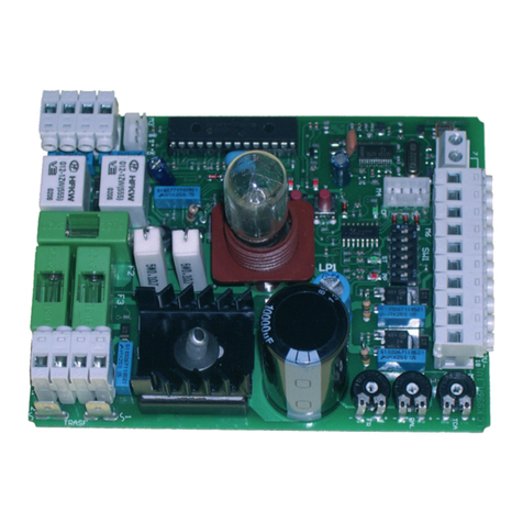
LED DI DIAGNOSI
F1 fusibile linea 230V 6.3 A.
F2 fusibile 24 V 1.6 A.
DL2 led rosso di segnalazione pulsante aperto-chiuso.
DL3 led verde di segnalazione pulsante di stop.
DL4 ledverdedisegnalazionenecorsaapertura.
DL5 ledverdedisegnalazionenecorsachiusura.
DL6 led verde di segnalazione sicurezza in chiusura
LED1 led segnalazione 24V.
S1 slot per inserimento scheda ricevente.

8
K898M
Français
• LOGIQUEAVECMICROPROCESSEUR
• DIODEÉLECTROLUMINESCENTED’AUTODIAGNOSTIC
• PROTECTIONENTRÉELIGNEPARFUSIBLE
• LIMITEURDECOUPLEÉLECTRONIQUEINCORPORÉ
• CONTRÔLEÉLECTRONIQUECOUPLEDETRAVAIL
• CIRCUITDECLIGNOTEMENTINCORPORÉ
• CONNECTEURPOURRÉCEPTEUR
BORNES DE CONNEXION À L’ARMOIRE DE COMMANDE K898M
1-2-3 sortie moteur; 1 = phase ouverture; 2 = commun; 3 = phase fermeture
4-5- 6 sortie moteur supplémentaire; 4 = phase fermeture; 5 = commun; 6 = phase ouverture
7-8 alimentation 230 V.c.a. 50/60 Hz.
9-10 sortie clignotant 230 V.c.a.
11-12 sortie éclairage automatique auxiliaire 230 V.c.a.
13-18 entrée bouton Ouvre/Ferme (contact Normalement Ouvert): pour les modalités de
fonctionnement, voir les fonctions du dip-switch n° 2-3; 18 = Commun
14-18 bouton Stop contact NF (Normalement Fermé). Après l’arrêt, l’automatisme repart en
ouvrant et seulement après une commande du bouton de marche ou de l’émetteur.
18 = Commun
15-18 entrée Microinterrupteur d’ouverture (contact Normalement Fermé); 18 = Commun
16-17 entrée Microinterrupteur de fermeture (contact Normalement Fermé); 18 = Commun
17-18 entrée bord sensible (barre palpeuse mécanique) ou autres dispositifs de protection
tels que les photocellules (contact N C); 18 = Commun
19-20 sortie 24 V c.a. pour alimentation dispositifs de sécurité et/ou autre (photocellules,
barres palpeuses mécaniques, relais pour éclairages, etc.).
21-22 sortie 2° canal radio
Note : pour le branchement d’autres dispositifs au deuxième canal du récepteur
radio (éclairage de zone, actionnement de pompes ou des charges lourdes),
utilisez un relais auxiliaire.
23-24 entrée Antenne radio: 23 = conducteur extérieur, 24 = central
RÉGLAGESLOGIQUESTRIMMER
TL Trimmer de réglage temps de travail (5-120 s), c’est-à-dire le temps que la porte
basculante met à effectuer une manœuvre entière. Le comptage commence à
chaque impulsion de commande. Il est conseillé d’effectuer le réglage avec quelques
secondes de plus que le temps nécessaire.

9
K898M
TCA Trimmer de réglage du temps de pause (5-120 s), c’est-à-dire le temps que la porte
basculante reste arrêtée en ouverture avec TCA abilitè. Le comptage commence
àlandutempsdetravailenouvertureouquandlemicrointerrupteurd’ouverture
est atteint. Il s’interrompt à l’arrivée d’une commande manuelle de fermeture et se
désactive momentanément à une commande de stop.
RCM Sélecteur à crans pour réglage de l’embrayage moteur, réglable sur 4 niveaux
de couple différents. Il est conseillé d’effectuer le réglage en partant d’une valeur
minimumetenl’augmentantsiellen’estpassufsantepourouvrirlaportebasculante,
le portail ou le volet. On applique ainsi le couple minimum pour le déplacement de la
porte basculante, du portail ou du volet et un heurt éventuel contre les choses et/ou
les personnes est ainsi sans conséquences
RÉGLAGESLOGIQUESDIP-SWITCH
N°1 OFF:la fermeture a besoin d’une commande distincte
ON: après ouverture totale, la fermeture du portail est automatique après écoulement
du temps programmé sur le temporisateur T.C.A
N°2 OFF: avec l’automatisme en fonction, une série de commandes d’ouverture/fermeture
porte le portail à effectuer une OUVERTURE-STOP-FERMETURE-STOP-
OUVERTURE-STOP (fonction pas-à-pas)
ON: dans les mêmes conditions, la même série de commandes porte le portail à
effectuer une OUVERTURE-FERMETURE-OUVERTURE-FERMETURE, etc.
N°3 OFF: (no reverse) le portail ignore les commandes de fermeture durant l’ouverture.
ON: le portail se comporte comme l’établit le dip-switch n°2
N°4 OFF: Il est possible de connecter au bouton ouvre-ferme un temporisateur/horloge en
mesure de gérer l’ouverture et la fermeture suivant par plages horaires (Entrée
d’usine/établissement)
ON: le bouton ouvre-ferme se comporte normalement.
N°5 OFF: après le start la porte commencera immédiatement sa manœuvre
ON: préclignotement activé, à chaque début de manœuvre, le clignotant fonctionnera
pendant environ 3 secondes avant que la porte commence à bouger.
ATTENTION:
Pour chaque paire de bornes aboutissant à un contact NF qui n’est pas utilisé, il faut effectuer
un court-circuit pour pouvoir garantir le fonctionnement normal de l’armoire de commande.
L’installation de mise à la terre de la porte basculante, du portail ou du volet doit être conforme
aux normes en vigueur. Le Constructeur décline toute responsabilité pour les dommages
dérivant de l’éventuelle non-observation des prescriptions.
DEL DE DIAGNOSTIC
F1 fusible ligne 230V 6.3 A.
F2 fusible 24 V 1.6 A.
DL2 del rouge de signalisation bouton ouvert-fermé.
DL3 del verte de signalisation bouton de stop.
DL4 delvertedesignalisationmicrointerrupteurdendecourseouverture.
DL5 delvertedesignalisationmicrointerrupteurdendecoursefermeture.
DL6 del verte de signalisation sécurité en fermeture.
LED1 del signalisation 24V.
S1 fente pour récepteur embrochable.

10
K898M
English
• MICROPROCESSOR-CONTROLLED LOGIC
• DIAGNOSTIC LEDS
• LINE INPUT PROTECTION WITH FUSE
• INCORPORATED ELECTRONIC TORQUE LIMITER
• ELECTRONIC PEAK LOAD CONTROL
• INCORPORATED FLASHING LIGHT
• CONNECTOR FOR RECEIVER BOARD
CONNECTION TO THE TERMINAL BOARD
1-2-3 motor output; 1 = opening phase; 2 = common; 3 = closing phase
4-5- 6 auxiliary motor output; 4 = closing phase; 5 = common; 6 = opening phase
7-8 power supply 230 Vac 50/60 Hz.
9-10 outputforashinglight230Vac
11-12 output for auxiliary courtesy light 230 Vac
13-18 input for open/close push button (normally-open contact): for usage, see the functions
of dip switches 2-3; 18 = Common
14-18 Stop push button NC (normally closed) contact. After a stoppage, the system always
starts again with an opening phase and only after receiving a command from the On
button or radio transmitter. 18 = Common
15-18 input for opening limit switch (normally closed contact); 18 = Common
16-17 input for closing limit switch (normally closed contact); 18 = Common
17-18 Input for pressure-sensitive edge (mechanical edge) or other safety devices, e.g.
photocells (NC contact); 18 = Common
19-20 24 Vac output for powering safety and/or other devices (photocells, mechanical edge,
relays for lighting, etc).
21-22 output for 2nd radio channel
Warning: to connect other devices to the 2nd Radio Channel (area lighting,
pumps, etc.), use an additional auxiliary relay.
23-24 input for radio aerial: 23 = braid, 24 = main cable
LOGIC ADJUSTMENTS TRIMMER
TL Trimmer for adjusting operating time (5-120 sec), or the time the overhead door
takes to complete a maneuver. The count begins each time a command is given. It is
advisable to adjust the time to a few seconds longer than is really necessary.

11
K898M
TCA Trimmer for adjusting the pause (5-120 sec), or the time the door remains
open with the TCA is enable. The count begins at the end of the operating time
for the opening phase or when reaching the opening limit switch. It stops when a
manual closing command is given and is temporarily disabled when a stop command
is given.
RCM Selector for motor clutch adjustment, it has four positions for adjusting
the motor torque to four different levels. It is advisable to adjust this starting from
aminimumvalueandincreasing said valueifitisnotsufcientto openthedoor,
thus exerting the minimum torque needed to move the door so that any accidental
bumping against persons or property will cause the least possible damage.
LOGIC ADJUSTMENTS DIP-SWITCHES
N°1 OFF: closingissubjecttoaspeciccommand
ON: after completing an opening, the closing of the gate takes place automatically
after a certain time interval set by means of the trimmer T.C.A.
N°2 OFF: with the automation enabled, a series of opening and closing commands induces
the gate to perform an OPENING-STOPPING-CLOSING-STOPPING-OPENING-
STOPPING type of cycle (step-by-step operation)
ON: in the same conditions, the same set of commands makes the gate perform an
OPENING-CLOSING OPENING-CLOSING type of sequence.
N°3 OFF: (no reverse) during opening the gate ignores any closing commands
ON: the gate’s behavior depends on the position of dip switch No.2
N°4 OFF: a timer can be connected to the input for the open/close button to have the gate
open and close at certain times of day (e.g. for factory entrances)
ON: the open/close button works normally.
N°5 OFF: when the gate is started, it will move immediately.
ON: preashing enabled, each time the gate is operated the light starts ashing 3
seconds before the gate begins to move.
IMPORTANT:
Each pair of terminals attached to an NC contact that is not in use must be short-circuited in
order to ensure the proper operation of the board.
The door’s earthing system must comply with current standards. The manufacturer will accept
no liability for any damage deriving from failure to comply with this requirement.
LED DI DIAGNOSI
F1 fuse on power supply line 230V 6.3 A.
F2 fuse 24 V 1.6 A.
DL2 red led for signaling open/close button operation.
DL3 green led for signaling stop button operation.
DL4 green led for signaling opening limit switch operation.
DL5 green led for signaling closing limit switch operation.
DL6 green led for signaling safety device in closing phase.
LED1 led for signaling 24V.
S1 slot for inserting receiver board.

12
K898M
DICHIARAZIONE DI CONFORMITA’ DECLARATION OF CONFORMITY KONFORMITÄTSERKLÄRUNG
(ai sensi della Direttiva Europea UE89/392 AlI. II.A) (European Directive 89/392 All. Il.A) (gemäß der Europäischen RichtlinieUE89/392 Anl. Il.A)
DECLARATlON DE CONFORMITY DECLARACIÓN DE CONFORMIDAD
(aux termes de la Directive européenne UE89/392 All. II.A) (según la Directiva Europea UE89/392 Anex. Il.A)
Fabbricante / Manufacturer / Hersteller / Fabricant / Fabricante: TAU s.r.l.
Indirizzo / Address / Adresse / Adresse / Dirección: Via E. Fermi, 43
36066 - Sandrigo
VICENZA - ITALY
- Dichiara sotto la propria responsabilità che il prodotto:
- Declares under its own responsibility that the following product:
- Erklärt auf eigene Verantwortung, daß das Produkt:
- Déclare sous sa propre responsabilté que le produit:
- Declara, bajo su propria responsabilidad, que el producto:
Quadro di comando / Control panel / Schalttafel / Armoire de commande / Cuadro de mando:
K898M
- È conforme ai requisiti essenziali di sicurezza delle direttive:
- It also complies with the main safety requirements of the follwing Directives:
- Es entspricht den grundlegenden Sicherheitsbedingungen der Direktiven:
- Est conforme aux exigences essentielles de sécurité des Directives:
- Es conforme a los requisitos esenciales de seguridad de las Directivas:
APPARECCHIATURE RADIO / RADIO SETS / RADIOAPPARATE / INSTALLATIONS RADIO /
RADIOEQUIPOS
1999/5/CE
BASSA TENSIONE / LOW VOLTAGE / NIEDERSPANNUNG / BASSE TENSION / BAJA TENSION
73/23/CEE, 93/68/CEE (EN 60335-1 (1998))
DIRETTIVA MACCHINE - COMPATIBILITÀ ELETTROMAGNETICA / MACHINERY DIRECTIVE
- ELECTROMAGNETIC COMPATIBILITY / MASCHINENRICHTLINIE - ELEKTROMAGNETISCHE
KOMPATIBILITÄT/DIRECTIVEMACHINES-COMPATIBILITÉÉLECTROMAGNÉTIQUE/DIRECTIVA
DE MÁQUINAS - COMPATIBILIDAD ELECTROMAGNETICA
89/336/CEE, 93/68/CEE, 98/37/CE
(EN 50081-1, EN 50081-2, EN 61000-3-2, EN 61000-3-2/A1, EN 61000-3-2/A2, EN 61000-3-2/A14, EN
61000-3-3, EN 61000-6-2, ETSI EN 300220-3, ETSI EN 301489-3, ETSI EN 301489-1)
- nonché alle loro modicazioni e aggiornamenti, e alle disposizioni che ne attuano il recepimento
all’interno dell’Ordinamento Legislativo Nazionale del paese di destinazione e utilizzo della macchina.
- and any subsequent revisions thereof, and comply with the provisions that implement said directives in
the national legislation of the country of destination where the products are to be used.
- sowie mit ihren Änderungen und Neubearbeitungen und den Verordnungen für deren Wahrnehmung
innerhalb der Gesetzgebung des Bestimmungs - und Benutzungslandes der Maschine.
- ainsiqu’àleursmodicationsetmisesàjour,etauxdispositionsquilestransposentdanslecadredu
Système Législatif National du pays de destination et d’emploi de la machine.
- así como también sus modicaciones y actualizaciones, y las disposiciones de adaptación del
Ordenamiento Legislativo Nacional del país de destino y utilización de la máquina.
SANDRIGO, 09/01/2004
Il Rappresentante Legale / The legal Representative
Der gesetzliche Vertreter / Le Représentant Légal
El Representante Legal
_________________________________________
Bruno Danieli

13
K898M

Garanzia TAU: condizioni generali ♦ ITALIANO
La garanzia della TAU ha durata di 24 mesi dalla data di acquisto dei prodotti (fa fede il documento scale di vendita, scontrino o fattura, che deve essere conservato allegato alla presente).
Il cliente TAU ha diritto ad usufruire della garanzia qualora abbia compilato ed inviato entro 10 giorni dalla data di installazione dell’apparecchiatura l’apposito certicato.
La garanzia comprende la riparazione con sostituzione gratuita (franco sede TAU: spese di imballo e di trasporto sono a carico del cliente) delle parti che presentano difetti di lavorazione o vizi di materiale
riconosciuti dalla TAU.
In caso di intervento a domicilio, anche nel periodo coperto da garanzia, l’utente è tenuto a corrispondere il “Diritto sso di chiamata” per spese di trasferimento a domicilio, più manodopera.
La garanzia decade nei seguenti casi:
• Qualora il guasto sia determinato da un impianto non eseguito secondo le istruzioni fornite dall’azienda all’interno di ogni confezione.
• Qualora non siano stati impiegati tutti componenti originali TAU per l’installazione dell’automatismo.
•
Qualora i danni siano causati da calamità naturali, manomissioni, sovraccarico di tensione, alimentazione non corretta, riparazioni improprie, errata installazione, o altre cause non imputabili alla TAU.
• Qualora non siano state effettuate le manutenzioni periodiche da parte di un tecnico specializzato secondo le istruzioni fornite dall’azienda all’interno di ogni confezione.
• Usura dei componenti.
La riparazione o la sostituzione dei pezzi durante il periodo di garanzia non comporta un prolungamento del termine di scadenza della garanzia stessa.
The TAU Guarantee: general conditions ♦ ENGLISH
TAU guarantees this product for a period of 24 months from the date of purchase (as proved by the sales document, receipt or invoice which must be attached to this guarantee).
The guarantee is only valid if customers ll in and send the relative certicate no later than 10 days after product installation.
This guarantee covers the repair or replacement at TAU’s expense (ex-works TAU: packing and transport at the customer’s expense) of parts that TAU recognises as being faulty as regards workmanship or materials.
For visits to the customer’s facilities, also during the guarantee period, a “Call-out fee” will be charged for travelling expenses and labour costs.
The guarantee does not cover the following cases:
• If the fault was caused by an installation that was not performed according to the instructions provided by the company inside the product pack.
• If original TAU spare parts were not used to install the product.
• If the damage was caused by an Act of God, tampering, overvoltage, incorrect power supply, improper repairs, incorrect installation, or other reasons that do not depend on TAU.
• If a specialised maintenance man does not carry out routine maintenance operations according to the instructions provided by the company inside the product pack.
• Wear of components.
The repair or replacement of pieces under guarantee does not extend the guarantee period.
TAU-Garantie: Allgemeine Bedingugen ♦ DEUTSCH
Die Garantie der Firma TAU hat 24 Monate Gültigkeit ab Kaufdatum (das Datum muss durch eine Quittung oder Rechnung belegt sein, die zusammen mit dem vorliegenden Garantieschein aufbewahrt werden muss).
Der Kunde der Firma TAU hat nur Anspruch auf die Garantieleistungen, falls er die Bescheinigung ausgefüllt und innerhalb von 10 Tagen ab Installationsdatum der Apparatur eingesendet hat.
Die Garantie schließt die Reparatur mit kostenlosem Ersatz (ab Werk der Firma TAU: Verpackungs- und Transportkosten gehen zu Lasten des Kunden) jener Teile ein, die von TAU anerkannte Fabrikations- oder Materialfehler
aufweisen.
Im Falle von Eingriffen am Standort des Kunden, auch in der Garantiezeit, hat der Kunde ein “feste Abrufgebühr” für die Reisekosten zum Standort des Kunden und die Arbeitskraft zu zahlen.
Die Garantie wird in folgenden Fällen ungültig:
• wenn der Defekt durch eine Installation verursacht ist, die nicht nach den in jeder Packung enthaltenen Herstelleranweisungen erfolgte.
• wenn für die Installation der Vorrichtung auch andere Teile als Original-TAU-Komponenten verwendet wurden.
• wenn die Schäden durch Naturkatastrophen, Handhabungen, Spannungsüberlasten, unkorrekte Versorgung, unsachgemäße Reparaturen, falsche Installation oder sonstiges, für das die Firma TAU keine
Verantwortung hat, verursacht sind.
• wenn die regelmäßigen Wartungsarbeiten nicht durch einen Fachtechniker nach den in jeder Packung enthaltenen Herstelleranweisungen ausgeführt worden sind.
• Verschleiß den Komponenten.
Reparatur oder Ersatz von Teilen während der Garantiezeit führt zu keiner Verlängerung derselben.
Garantie TAU: conditions générales ♦ FRANÇAIS
La garantie TAU a une durée de 24 mois à compter de la date d’achat des produits (le document scal de vente, ticket de caisse ou facture, fait foi et doit être conservé avec la présente garantie).
Le client TAU a le droit de bénécier de la garantie s’il a rempli et renvoyé le certicat de garantie dans les 10 jours qui suivent la date d’installation de l’automatisme.
La garantie comprend la réparation avec remplacement gratuit (départ usine TAU: frais d’emballage et de transport à la charge du client) des parties qui présentent des défauts de fabrication ou des vices de matériau
reconnus par TAU.
En cas d’intervention à domicile, y compris dans la période couverte par la garantie, l’utilisateur est tenu de verser le “Forfait d’intervention” correspondant au coût du déplacement à domicile, plus la main d’œuvre.
La garantie n’est plus applicable dans les cas suivants :
• Si la panne est provoquée par une installation qui n’a pas été effectuée suivant les instructions fournies par le constructeur et présentes à l’intérieur de chaque emballage.
• Si l’on n’a pas utilisé que des pièces originales TAU pour l’installation de l’automatisme.
• Si les dommages sont causés par des calamités naturelles, des actes de malveillance, une surcharge de tension, une alimentation électrique incorrecte, des réparations impropres, une installation
erronée ou d’autres causes non imputables à TAU.
• Si l’automatisme n’a pas été soumis aux maintenances périodiques de la part d’un technicien spécialisé selon les instructions fournies par le constructeur à l’intérieur de chaque emballage.
• Usure des composants.
La réparation ou le remplacement des pièces durant la période de garantie ne comporte pas le prolongement de la date d’expiration de la garantie en question.
Garantía TAU: condiciones generales ♦ ESPAÑOL
La garantía de TAU tiene una cobertura de 24 meses a partir de la fecha de compra de los productos (la fecha válida es la que gura en el comprobante de venta, recibo o factura, que deberá conservarse junto con la
presente). El cliente TAU tiene derecho a la garantía cuando haya cumplimentado y remitido el certicado antes de 10 días desde la fecha de instalación del equipo.
La garantía incluye la reparación con sustitución gratuita (franco fábrica TAU: gastos de embalaje y de transporte a cargo del cliente) de las piezas que tuvieran defectos de fábrica o vicios de material reconocidos por TAU.
En el caso de reparación a domicilio, incluso en el período cubierto por garantía, el usuario deberá hacerse cargo de los gastos de desplazamiento a domicilio, más la mano de obra.
La garantía caduca en los siguientes casos:
• Si la avería ha sido determinada por una instalación realizada sin respetar las instrucciones dadas por la empresa que se encuentran en el interior de cada embalaje.
• Si no se han utilizado todos los componentes originales TAU para la instalación del automatismo.
• Si los daños han sido causados por catástrofes naturales, modicaciones, sobrecargas de tensión, alimentación incorrecta, reparaciones inadecuadas, instalación incorrecta u otras causas no imputa-
bles a TAU.
• Si no se han efectuado los trabajos de mantenimiento periódico por parte de un técnico especializado, según las instrucciones dadas por la empresa que se encuentran en el interior de cada embalaje.
• Usura de los componentes.
La reparación o sustitución de las piezas durante el período de garantía no implican la extensión de la garantía.
Garantia TAU: condições gerais ♦ PORTUGUÊS
A garantia TAU tem uma duração de 24 meses a contar da data de compra dos produtos (o documento scal de venda, recibo ou factura deverá ser guardado juntamente com a garantia do produto).
Esta garantia só é válida se o cliente a preencher e a enviar o respectivo certicado de garantia nos 10 dias seguintes aos da instalação do produto.
Esta garantia cobre a reparação ou substituição a espensas TAU (à saída da fábrica: embalagem e transporte por conta do cliente) das peças que que apresentem defeitos de fabrico ou material defeituoso reconhe-
cidos pela TAU. Em caso de reparação ao domicílio, inclusivé no período coberto pela garantia, despesas de deslocação mais mão-de-obra serão cobradas ao utilizador.
A garantia não se aplica nos seguintes casos:
• Se a avaria for motivada por uma instalação que não respeita as instruções fornecidas pelo fabricante que se encontram dentro de cada embalagem.
• Se não foram utilizados sómente peças originais TAU para a instalação do automatismo.
•
Se os danos forem causados por calamidades naturais, modicações, sobrecargas de tensão, alimentação incorrecta, reparações inadequadas, instalação incorrecta ou outros casos não imputáveis à TAU.
• Se o automatismo não foi submetido às inspecções periódicas por parte do técnico especializado, conforme as instruções fornecidas pelo fabricante no interior de cada embalagem.
• Componentes de desgaste.
A reparação ou substituição das peças no período de garantia não implica a extensão da garantia.

Certicato di Garanzia TAU - The TAU Guarantee Certicate - Certicat de Garantie TAU - TAU- Garantieschein - Certicado de Garantía TAU - Certicado de Garantia TAU
I- IMPORTANTE: durante l’installazione è fondamentale che l’installatore compili esattamente il presente certicato di garanzia. Il certicato dovrà essere inviato alla TAU entro 10 giorni dalla data di installazione.
In questo modo l’utente avrà la certezza che il prodotto installato potrà godere della garanzia per la durata di 24 mesi.
GB- IMPORTANT: during installation, the installer must correctly ll in this guarantee certicate. The certicate must be sent to TAU within 10 days from the date of installation. The user will thus be sure that the installed
product will enjoy a 24 month guarantee.
F- IMPORTANT: Au moment de l’installation il est fondamental que l’installateur remplisse intégralement ce certicat de garantie. Le certicat devra être envoyé à TAU dans les 10 jours qui suivent la date d’installation. De cette
manière, l’utilisateur aura la certitude que le produit installé pourra bénécier d’une garantie de 24 mois.
D- ACHTUNG: Während der Installation ist es wichtig, daß der Installateur diesen Garantieschein genau ausfüllt. Der Schein muß der TAU innerhalb von 10 Tagen ab dem Installationsdatum übermittelt werden. Auf diese
Weise hat der Kunde die Gewißheit, daß für die installierten Produkte die 24-monatige Garantie in Anspruch genommen werden kann.
E- IMPORTANTE: durante la instalación es fundamental que el instalador rellene este certicado de garantía. El certicado se debe enviar a TAU antes de transcurridos 10 días desde la fecha de instalación. Así, el cliente tendrá
la certeza de que el producto instalado está cubierto por la garantía por un plazo de 24 meses.
P- IMPORTANTE: Esta garantia só é válida se o cliente a preencher e a enviar a TAU o respectivo certicado de garantia nos 10 dias seguintes aos da instalação do produto. Só assim o cliente terá a certeza que o producto
instalado está coberto pela garantia num período de 24 meses.
TIMBRO DEL RIVENDITORE - RETAILER’S STAMP
CACHET DU REVENDEUR - STEMPEL DES HÄNDLERS
SELLO DEL REVENDEDOR - CARIMBO DO REVENDEDOR
TIMBRO DELL’INSTALLATORE - INSTALLER’S STAMP
CACHET DE L’INSTALLATEUR - STEMPEL DES INSTALLATEURS
SELLO DEL INSTALADOR - CARIMBO DO INSTALADOR
DATI DELL’UTENTE FINALE - USER INFORMATION
COORDONNÉES DE L’UTILISATEUR FINAL - DATEN DES ENDABNEHMERS
DATOS DEL USUARIO FINAL - INFORMAÇÃO CLIENTE FINAL
Data di acquisto - Date of purchase:
Date d’achat - Kaufdatum:
Fecha de compra - Data de compra:
Data di installazione* - Date of installation*:
Date d’installation* - Installationsdatum*:
Fecha de instalación* - Data de Instalação*:
Cognome/Surname/Nom/Nachname/Apellido/Apelido
________________________________
Nome/Name/Prénom/Name/Nombre/Nome
______________________________
Via/Road/Rue/Straße/Calle/Avenida
______________________________
Cap/Post code/Code postal/BLZ/C.P./ Código postal
______________________________
Telefono/Tel./Téléphone/Telefon/Teléfono/ Telefone
______________________________
* E’ obbligatorio riportare la data di installazione
* Das Installationsdatum muß angeführt sein
* The date of installation must be indicated
* Es obligatorio indicar la fecha de instalación * E’obrigatorio comunicar a data da instalação
* Il est obligatoire d’indiquer la date d’installation
--------------------------------------------------------------------------------------

Certicato di Garanzia TAU - The TAU Guarantee Certicate - Certicat de Garantie TAU - TAU- Garantieschein - Certicado de Garantía TAU - Certicado de Garantia TAU
I- Riportare l’etichetta adesiva (o in mancanza il numero di matricola) relativa ad ogni prodotto facente parte dell’impianto.
Attenzione: la garanzia non ha validità nel caso in cui non siano stati impiegati tutti componenti originali TAU per l’installazione dell’impianto automatico di apertura.
GB- Attach the adhesive label (or the series number) of each product in the system.
Attention: the guarantee is not valid if TAU original components are not used to install the automatic opening system.
F- Reporter l’étiquette adhésive (ou à défaut, le numéro matricule) relative à tous les produits composant l’installation.
Attention la garantie n’est pas valable si des composants non originaux TAU ont été utilisés pour l’installation de l’automatisme d’ouverture.
D- Die Daten auf dem Aufkleber (oder wenn dieser nicht vorhanden ist, die Matrikelnummer) sind für jedes Produkt der Anlage anzuführen.
Achtung! Die Garantie verfällt, wenn für die Installation der automatischen Öffnungsanlage nicht ausschließlich TAU-Original-Ersatzteile verwendet wurden.
E- Añada la etiqueta adhesiva (o, si faltara, el número de matrícula) de cada producto que forma parte del equipo.
Atención: la garantía no es válida si no se han empleado todos componentes originales TAU para la instalación del equipo automático de apertura.
P- Importante: O instalador terá que anexar a etiqueta adesiva (ou número de série) de cada produto pertencente ao sistema.
A garantia não se aplica nos se não foram utilizados sómente peças originais TAU para a instalação do automatismo.
Quadro elettrico di comando
Electric control panel
Coffret électrique de commande
Elektr. Schaltpult
Cuadro eléctrico de mando
Quadro eléctrico de comando
Serial n°_______________
Radio ricevente
Radio receiver
Récepteur
Funkempfänger
Radiorreceptor
Receptor
Serial n°_______________
Fotocellule o/e altro
Photocell and/or alternative
Photocellules ou/etautre
Photozellen bzw. Sonstiges
Fotocélulas o demás
Fotocélulas o outro
Serial n°_______________
Motore
Motor
Moteur
Motor
Motor
Motor
Serial n°_______________
Motore
Motor
Moteur
Motor
Motor
Motor
Serial n°_______________
I- Nel caso di un impianto comprendente più prodotti TAU soggetti a garanzia raggruppare le etichette adesive in un unico certicato di garanzia o spedire in un’unica busta chiusa tutti i certicati di garanzia relativi ai prodotti utilizzati nell’impianto.
GB- In case of a system containing several TAU products under guarantee, collect the sticky labels in a single guarantee certicate and send all the guarantee certicates concerning the products used in the plant in a closed envelope.
F- Si une installation comprend plusieurs produits TAU sujets à garantie, regrouper les étiquettes adhésives sur un seul certicat de garantie ou expédier dans une seule enveloppe fermée tous les certicats de garantie relatifs aux produits utilisés dans l’installation.
D- Bei einer Anlage mit mehreren Produkten von TAU, die unter die Garantie fallen, sind die Daten der Aufkleber in einem einzigen Garantieschein anzuführen. Es können aber auch sämtliche Garantiescheine für die in der Anlage verwendeten Produkte in
einem geschlossenen Kuvert übermittelt werden.
E- Si una instalación incluyera varios productos TAU cubiertos por garantía, junte todas las etiquetas adhesivas en un solo certicado de garantía o envíe en un sobre único todos los certicados de garantía referidos a los productos usados en la instalación.
P- Se a instalação incluir varios produtos TAU, o instalador terá que anexar a etiqueta adesiva de cada produto pertencente ao sistema.
I dati personali riportati sul presente tagliando saranno utilizzati allo scopo di far valere la garanzia e per un eventuale invio di materiale informativo. Saranno trattati in ottemperanza alla legge sulla privacy 675/96 (e modiche successive).
The personal data specied on the present coupon shall be used to enforce the guarantee and for eventual forwarding of informative material, and shall be treated in compliance with the privacy law 675/96 (and subsequent amendments).
Die auf dem vorliegenden Schein angegebenen persönlichen Daten werden dazu benutzt, die Garantie geltend zu machen und eventuelles Informationsmaterial zu senden. Sie werden unter Einhaltung des Datenschutzgesetzes 675/96 behandelt (und ihren nachfolgende
Änderungen).
Les données personnelles contenues dans ce coupon seront utilisées pour faire valoir la garantie et pour l’envoi éventuel de matériel d’information. Elles seront traitées dans le respect de la loi italienne sur la protection des données personnelles n° 675/96 (et modications
successives).
Los datos personales que guran en el presente cupón se utilizarán para hacer valer la garantía y para un eventual envío de material informativo. Se tratarán cumpliendo todos los requisitos que obliga la ley sobre la privacidad 675/96 (y modicaciones sucesivas).
Os dados pessoais do usuário serão utilizados pela garantia e para Enviar material informativo. Os dados serão tratados de modo informatizado segundo o art.13 Lei 675/96 e suas sucessivas modicações.
Doc. cod. D-CGR0TAU00
----------------------------------------------------------------------------------------
rev. 06 del 16/04/2012
This manual suits for next models
1
Table of contents
Other tau Control Panel manuals