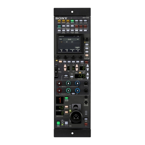
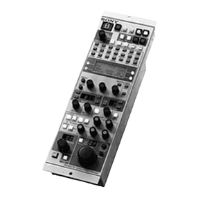
Sony RCP-3100 User manual

Remote Control Panel
Operating Instructions
Before operating the unit, please read this manual thoroughly
and retain it for future reference.
RCP-3100
© 2018 Sony Corporation
5-001-747-11 (1)

2
Table of Contents
Precautions ............................................................... 2
Overview.................................................................... 3
Features ..........................................................................3
System Configuration Examples .....................................3
Supported Devices ..........................................................6
Camera Operations .........................................................6
Names and Functions of Parts ................................ 6
Operation Panel ..............................................................6
Connector Panel ...........................................................11
Mounting.................................................................. 12
Precautions when Connecting ......................................12
Settings ................................................................... 12
Setting the Control Panel ..............................................12
Configuring Directly from the Control Panel ....... 13
Starting and Exiting Configuration Mode .......................13
Setting the Control Panel ..............................................13
Control Panel Settings ..................................................14
Configuring from the Web Menu........................... 17
Web Configuration Connection Example ......................17
Setting Up Web Access ................................................17
Web Menu Example ......................................................18
Web Menu Operation ....................................................20
Web Menu Settings .......................................................21
Specifications ......................................................... 23
Pin Assignment .............................................................23
Open Source Software Licenses ...................................24
Trademarks ...................................................................24
Precautions
Note on interference
Do not place mobile phones or similar devices on the control
panel. Doing so may result in malfunction of the unit.
On condensation
If the unit is suddenly taken from a cold to a warm location, or
if ambient temperature suddenly rises, moisture may form on
the outer surface of the unit and/or inside of the unit. This is
known as condensation. If condensation occurs, turn off the
unit and wait until the condensation clears before operating
the unit. Operating the unit while condensation is present may
damage the unit.
Consumable parts
The life expectancy of the electrolytic capacitor is about 5
years under normal operating temperatures and normal usage
(8 hours per day; 25 days per month).
If usage exceeds the above normal usage frequency, the life
expectancy may be reduced correspondingly.
Network security
SONY WILL NOT BE LIABLE FOR DAMAGES OF ANY KIND
RESULTING FROM A FAILURE TO IMPLEMENT PROPER
SECURITY MEASURES ON TRANSMISSION DEVICES,
UNAVOIDABLE DATA LEAKS RESULTING FROM
TRANSMISSION SPECIFICATIONS, OR SECURITY
PROBLEMS OF ANY KIND.
Depending on the operating environment, unauthorized third
parties on the network may be able to access the unit. When
connecting the unit to the network, be sure to confirm that the
network is protected securely.

3
Overview
Features
The RCP-3100 is a remote control panel for configuring and
controlling Sony studio and broadcast cameras. Up to five
units can be mounted in a 19-inch EIA rack.
Besides the basic operations, you can adjust paint functions
using the multi-function block, select and register scene files,
and control the menu of the camera/BPU/CCU.
You can connect the CCU and camera using a CCA-5 cable or
construct a networked system using a LAN.
Multi-function block
You can select the electronic shutter and the BLACK GAMMA,
SATURATION, and DETAIL functions to adjust or turn on/off.
You can also assign other paint functions to the BLACK
GAMMA and SATURATION buttons using the web menu.
Camera/BPU/CCU menu control
Camera/BPU/CCU menu display, cursor movement, item
selection, and operation cancellation are supported using the
buttons and knobs of the unit.
RCP ASSIGN knob
In a multi-camera system, you can change the device to
control using the RCP ASSIGN knob.
Configuring from the web
The settings of the unit, network, and assignable functions can
be configured and checked using a web browser.
Configuration information of the unit can be saved to a
personal computer.
System Configuration Examples
Restart all camera systems after changing the connection mode (CNS).
Legacy mode connection example
Bridge mode connection example
Note
Connect a camera control unit (CCU) and RCP with a CCA-5 cable.
HDCU3100
CNS: Legacy
CCU No.: (1–96, A–Z)
CCA-5 cable
RCP-3100
CNS: Legacy
HDC3100
• Connect CCU and RCP (one to one) using a LAN cable.
• Configure the IP address and CCU (Target) destination IP address.
HDCU3100
CNS: Bridge
IP address: 192.168.0.1
CCU No.: (1–96, A–Z)
LAN
cable
PoE hub
RCP-3100
HDC3100
CNS: Bridge
IP address: 192.168.0.101
Target IP address: 192.168.0.1
LAN
cable

4
PC Control mode connection example
• Configured using HZC-RCP5 Camera Remote Control Software.
• CCUs that support PC control are supported.
• Up to six RCP units can be connected.
• Connection example using the RCP Linkage function of HZC-RCP5.
HXCU-FB80
CNS: PC Control
IP address: 192.168.0.1
PC IP address: 192.168.0.201
CCU No.: 1
LAN
cable
PoE hub
HZC-RCP5
HXC-FB80
LAN cable
IP address: 192.168.0.201
RCP Linkage: ON
CNS: MCS
IP address: 192.168.0.101
Master IP address: 192.168.0.201
RCP No.: 6
RCP-3100
CNS: PC Control
IP address: 192.168.0.2
PC IP address: 192.168.0.201
CCU No.: 2
CNS: PC Control
IP address: 192.168.0.5
PC IP address: 192.168.0.201
CCU No.: 5
LAN
cable
LAN
cable
LAN cable

5
MCS mode connection example
• The master device controls the whole camera system.
• Configure the IP address of each device and the IP address of the master device.
• A master setup unit (MSU) or CNA-1 can be used as the master device.
• Centralized control of devices and assignment of device to control (RCP assignment) are
supported using MSU and HZC-CSM1.
HDCU3100
CNS: MCS
IP address: 192.168.0.1
Master IP address: 192.168.0.201
CCU No.: 1
PoE hub
RCP-3100
HDC3100
CNS: MCS
IP address: 192.168.0.101
Master IP address: 192.168.0.201
RCP No.: 1
LAN
cable
CNS: MCS
IP address: 192.168.0.2
Master IP address: 192.168.0.201
CCU No.: 2
CNS: MCS
IP address: 192.168.0.n
Master IP address: 192.168.0.201
CCU No.: n
CNA-1
MSU-1500
CNS: MCS
IP address: 192.168.0.201
Master/Client: Master
Device No.: (1)
LAN
cable
CNS: MCS
IP address: 192.168.0.102
Master IP address: 192.168.0.201
RCP No.: 2
CNS: MCS
IP address: 192.168.0.(100+m)
Master IP address: 192.168.0.201
RCP No.: m
LAN
cable
LAN
cable
LAN
cable
LAN
cable
LAN
cable
or
Master device

6
Supported Devices
This unit supports connection to the following devices.
• HXC-FB75/HXC-FB80/HXC-P70
• HXCU-FB70/HXCU-FB80/HXCU-TX70
• HSC300RF/300R/100RF/100R
• HSCU300RF/300R
• HDC1700/2500 series
• HDCU2000/2500 series
• HDC4300
• HDC-P43
• HDCU4300
• HDCU3100/3170
• HDC3100/3170/3500
• CA4000
• BPU4000/4500A
• BRC-H800/X1000
• HZC-RCP5
• Correct operation may not be possible depending on the
firmware version. Be sure to update to the latest version
before use.
• The functions available on the control panel may be limited
depending on the connected camera. Some controls may
not function with certain cameras, but this is not a
malfunction.
Camera Operations
Camera control permissions (panel active,
PARA, and IRIS/MB active)
By combining an MSU and RCP units, you can operate one
camera device from multiple control panels, or multiple
cameras from one MSU. This is called a “multi-camera
system.” A multi-camera system can be implemented by
establishing a LAN connection in MCS mode.
To prevent unintentional operation in a multi-camera system,
permission is granted to operate the cameras for either the
connected MSU or RCP only. There are three types of
permission.
Panel active
Even if multiple control panels are connected to one camera,
only one control panel has the control permission. This panel
is referred to as “active.” A control panel that does not have
panel active can only be used to display the status.
PARA (parallel control)
By enabling the PARA function on a control panel that does not
have panel active, you can control cameras. The PARA
function is enabled from a control panel that does not have
panel active, but can be disabled from any control panel.
IRIS/MB (iris/master black) active
To prevent unintentional operation of the iris and master black,
you can choose the control panels on which to activate iris and
master black control. The PARA function does not operate.
Operation on a control panel on which panel active and PARA
are disabled will not change the state of the camera.
Names and Functions of
Parts
Operation Panel
Camera/panel control block
aPARA (parallel control) button
PARA function button. It allows simultaneous control with
another control panel that has panel active. However, iris and
master black are only enabled on control panels on which iris/
master black is active, and cannot be controlled
simultaneously.
Notes
Camera/panel
control block
Menu control
block
Function control
block
Adjustment block
Panel control/
status display block

7
bCAM PW (camera power) button
Press this button to supply power from the CCU to the camera.
cTest signal output selection button
This button lights when pressed to output a signal from the test
signal generator.
TEST: Camera test signal
BARS: Color bars signal
When the BARS button is lit, the function of the BARS button
takes priority. To select TEST, press the BARS button to turn
its light off.
dCLOSE (iris close) button
Press this button to close the iris of the lens connected to the
camera.
Pressing it when the auto iris is on changes the iris indication
to CLS (close). Pressing it when the auto iris is off closes the
lens iris without changing the iris indication. Pressing it again
cancels the iris closing, and the previous state of the iris value
is restored.
eCHARACTER (text information) button
CCU character button. Press this button to turn character
output of the CCU on/off, and to switch to the next page. When
this function is on, each press of the button switches to the
next page. In the on state, pressing and holding the button
switches to the last page. In the off state, character output is
stopped. For details about which video output connectors will
support character output, refer to the operation manual for the
connected device.
fSTANDARD button
Press this button to recall the standard state of the camera.
After the standard state is recalled, you can cancel the recall
by pressing this button again while it is lit.
g5600K button
Electronic color temperature correction function button. Press
this button to turn electronic color temperature correction
(5600K) on.
hAssignable button (F1)
You can assign any function to this button using the web menu.
For details, see “Configuring from the Web Menu” (page 17).
iATW button
ATW (auto tracing white balance) function button. Press this
button to turn ATW on.
jAWB (auto white balance) button
Press this button to start auto white balance adjustment. The
button is lit while this adjustment is in progress and goes out
when adjustment is finished. Pressing it again while
adjustment is in progress will stop automatic adjustment. The
button flashes to indicate the function is stopped. Press again
to stop the flashing indication.
kABB (auto black balance) button
Press this button to start auto black balance adjustment. The
button is lit while this adjustment is in progress and goes out
when adjustment is finished. Pressing it again while
adjustment is in progress will stop automatic adjustment. The
button flashes to indicate the function is stopped. Press again
to stop the flashing indication.
Menu control block
aTarget device selection (CAM/BPU/CCU) buttons
These select the target device for menu control. When a
device is selected, the corresponding button is lit. When all
button indications are not lit, no device is selected and menu
control is disabled.
1Menu control block
aOVERLAY button
Displays the OVERLAY status of the camera/BPU. The button
cannot be operated.
bDISP button
Press this button to show the operation status (DISP) of the
camera/BPU.
This is disabled when the CCU button on the target device to
control is selected.
cMENU button
Press this button to show the menu of the camera/BPU/CCU.
dSELECT knob
Turn this knob to move the cursor when the menu/operating
status display is displayed. Press the knob to select an item.
eCANCEL button
Press this button to cancel the selected item.
When BARS is selected for the test signal output, CAM/BPU
cannot be selected as the control target. If BARS is selected
when CAM or BPU is lit, the CAM or BPU device selection is
canceled.
Lighting state Meaning
On Power is being supplied to the camera.
Off Power is disconnected from the camera. It is not
supplied even if the button is pressed.
Slow flashing Power is disconnected from the camera. It is
supplied when the button is pressed.
Fast flashing Camera is starting up.
Note
Note

8
Function control block
aUSB connector
For use by service personnel.
bCONFIG button
Press this button to configure the unit in combination with
other buttons. For details, see “Configuring Directly from the
Control Panel” (page 13).
cSAVE button
Press this button to configure the unit in combination with
other buttons. For details, see “Configuring Directly from the
Control Panel” (page 13).
1Scene file control block
aScene file indicator
The indicator is lit when a scene file is read out. When scene
1 to 5 is read out, the correspondingly numbered button is lit.
When scene 6 or later is read out, only the SCENE FILE
indicator LED is lit.
bSCENE FILE (scene file selection) buttons and STORE
(scene file store) button
Use these buttons to store and read out scene files.
To store a scene file, press the STORE button so that it starts
flashing and press the desired number SCENE FILE button.
When the file is stored, the STORE button goes out. To cancel
storing a file, press the STORE button again so that the
STORE button goes out.
To read out a scene file, press the desired number SCENE
FILE button while the STORE button is not flashing.
The items stored in a scene file vary depending on the
connected camera.
2Multi-function block
aSLS/SHUTTER/ECS selection buttons
These select the operating mode of the electronic shutter.
The buttons will not light when pressed if the camera does not
have an electronic shutter function.
bAdjustment knob
Turn the adjustment knob to adjust the value displayed in the
adjustment display window.
cBLACK GAMMA/SATURATION/DETAIL selection
buttons
Press to select the function of the multi-function block. Press
the BLACK GAMMA, SATURATION, or DETAIL button to
select each function. The button for the selected function is lit
and the adjustment value is displayed in the adjustment
display window. The on/off status is displayed by the ON
button.
You can assign any function to BLACK GAMMA and
SATURATION using the web menu.
For details about assignable functions, see “Functions
assignable to the multi-function block” (page 22).
dAdjustment display window
This window displays the adjustment value of the selected
function.
eON button
Displays the on/off status of the selected function. Press this
button to switch between on and off status.
3Filter control block
aStandard value indicator
This indicator indicates if a standard value is configured using
the web menu. It is lit green in the standard state, and amber
in non-standard state.
bND filter selection buttons
These are lit when the unit has control permission for the ND
filter. When they are not lit, the camera has the control
permission. Pressing either the top or bottom button once
switches the control permission to the unit. If there is no filter
servo or the camera does not have an ND filter, these buttons
do not light and the control permission cannot be switched.
The (up) button changes the ND filters in order in the forward
direction. The (down) button changes them in the reverse
direction. Pressing and holding one of the buttons changes the
filters continuously.
cND filter display window
This window displays the ND filter that is currently selected.

9
dCC (color temperature conversion) filter selection
buttons
These are lit when the unit has control permission for the CC
filter. When they are not lit, the camera has the control
permission. Pressing either the top or bottom button once
switches the control permission to the unit. If there is no filter
servo or the camera does not have a CC filter, these buttons
do not light and the control permission cannot be switched.
The (up) button changes the CC filters in order in the forward
direction. The (down) button changes them in the reverse
direction. Pressing and holding one of the buttons changes the
filters continuously.
eCC (color temperature conversion) filter display
window
This window displays the CC filter that is currently selected.
4Master gain control block
aStandard value indicator
This indicator indicates if a standard value is configured using
the web menu. It is lit green in the standard state, and amber
in non-standard state.
bMaster gain selection buttons
These buttons adjust the sensitivity of the camera. Press the
(up) button to increase the sensitivity each time the button is
pressed, or press the (down) button to decrease the
sensitivity each time the button is pressed. Pressing and
holding one of the buttons changes the setting continuously.
cMaster gain display window
This window displays the currently configured master gain (dB
units).
Adjustment block
1White balance/black balance adjustment block
aWHITE (manual white balance) knobs
Turn to adjust the white balance manually. They adjust the R,
G, and B signals in order from left to right.
bBLACK/FLARE (manual black balance/manual flare
balance) knobs
When the FLARE button is not lit, these adjust the black
balance. When the FLARE button is lit, these adjust the flare
balance. They adjust the R, G, and B signals in order from left
to right.
cFLARE (flare balance adjustment mode) button
Press this button to switch the adjustment mode of the BLACK/
FLARE knobs. When lit, the knobs adjust the flare balance.
When not lit, the knobs adjust the black balance.

10
2Iris/master control black adjustment block
aCamera number/tally display window
This window displays an amber number for the camera
controlled by the unit. When a red tally signal is sent to the
camera, a black number is displayed and the background of
the number lights in red. When a green tally signal is sent to
the camera, a black number is displayed and the background
of the number lights in green. When a 3rd tally signal is sent to
the camera, a black number is displayed and the background
of the number lights in orange.
When multiple tally signals are sent to the camera, the
background is split into the corresponding individual colors.
During RCP assignment, the number of the target camera to
control flashes.
bRCP ASSIGN knob
Press and hold the knob so that the camera number flashes,
and turn the knob to change the camera number to be
assigned.
Press and hold the knob again till the number stops flashing to
assign the unit to the selected camera number.
The RCP assignment function can be used in PC Control
mode and MCS mode.
cIRIS/MB ACTIVE (iris/master black active) button
Press this button for iris and master black control permission.
The iris and master black can only be adjusted when this
button is lit. Pressing the PANEL ACTIVE button also causes
this button to light.
dAUTO IRIS button
Press this button to switch between auto and manual iris
adjustment. When the button is lit, auto adjustment is selected.
eAssignable button (F2)
You can assign any function to this button using the web menu.
For details, see “Configuring from the Web Menu” (page 17).
fIRIS display window
This window displays the iris setting as an F-number. If the
lens is closed, “CLS” is displayed.
gRELATIVE (relative value mode) button
Press to switch the mode of the IRIS control lever and master
black adjustment ring.
The button is lit in relative value mode.
Relative value mode (RELATIVE button is lit)
The iris and master black are adjusted relative to initial values
set at the positions of the IRIS control lever and master black
control ring when the RELATIVE button is turned on. The
variable range can be changed on the unit or using the web
menu. The initial value is 1/4.
You can also adjust the iris over a wider range than the IRIS
control lever using the COARSE knob.
Absolute value mode (RELATIVE button is not lit)
The IRIS control lever and master black adjustment ring
positions directly determine the iris and master black values.
Set the upper and lower limits of the iris adjustment using the
COARSE knob and SENS knob. Set the lower limit on the
CLOSE side using the COARSE knob, then set the upper limit
on the OPEN side using the SENS knob.
hMaster black display window
This window displays the master black setting value.
iEXT (lens extender) / F DROP indicators
EXT: Lights when the lens extender is used.
D EXT: Lights when the digital extender function is turned on.
F DROP: Lights when the F-drop function is active.
jSENS (iris adjustment range) knob
Turn this knob to manually adjust the iris in absolute value
mode. It does not function in relative value mode.
kCOARSE (iris coarse adjustment) knob
Turn this knob to manually adjust the iris.
lIRIS control lever
Use this lever to manually adjust the iris when the AUTO IRIS
button is not lit. When the AUTO IRIS button is lit, you can
perform fine adjustment of the reference value for auto
adjustment of the iris. You can output a preview signal by
pressing down on the lever.
For details about configuring input/output settings, see
“Configuring Directly from the Control Panel” (page 13) or
“Configuring from the Web Menu” (page 17).
mMaster black adjustment ring
Turn this ring to adjust the master black manually. The
adjustment value is displayed in the master black display
window.
Panel control/status display block
Note
11
aNETWORK indicator
Displays the status of the network connection.
bAssignable button (F3)
You can assign any function to this button using the web menu.
For details, see “Configuring from the Web Menu” (page 17).
cPREVIEW button
Press and hold to output a preview signal for as long as the
button is pressed.
For details about configuring input/output settings, see
“Configuring Directly from the Control Panel” (page 13) or
“Configuring from the Web Menu” (page 17).
dCABLE indicator
This indicates the communication status of the camera and
CCU.
eALARM indicator
This indicates the status of the unit and status of device
controlled by the unit.
fPANEL ACTIVE button
Press this button for control permission. It also functions to
prevent unintentional operation, because a camera cannot be
controlled from this control panel when this button and the
PARA button are not lit.
In an MCS mode system, panel active operation is disabled if
communication with the master is interrupted.
In this state, you can press and hold the PANEL ACTIVE
button to forcibly acquire panel active state.
gCALL button
This button is used for communication. When this button is
pressed, the tally indicator state for the camera or CCU
changes, and a call signal is sent. Similarly, a call signal can
be received from another device. When a call signal is sent (or
received), this button lights and the call sound plays. The call
sound can be selected in the menu.
Connector Panel
When power is supplied from the CCU/CNU connector or EXT
I/O connector, disable the PoE power from the network
connector.
aCCU/CNU REMOTE connector (8-pin multi-connector,
female)
Connect to the RCP/CNU connector of the CCU or the RCP
connector of the CNU.
b(Network) connector (RJ-45 8-pin)
Use to connect to a network. Connect to a 10BASE-T/
100BASE-TX hub using a network cable (shielded type,
category 5 or higher). This connector accepts power supply
from an IEEE802.3af compliant Power over Ethernet (PoE)
device.
cEXT I/O connector (D-Sub 9-pin, female)
Used for external interface connections.
Lighting state Meaning
On Connected with control device.
Flashing Cannot find control device.
Off Cannot connect to the camera network, or legacy
mode is being used.
Lighting state Meaning
On (green) Reception state is good.
On (yellow) Reception level is low.
On (red) Reception level is extremely low.
Off Power of the camera is off, or an error occurred in
communication.
Lighting state Meaning
On (red) An error occurred on the device controlled by the
unit.
On (green) The unit is starting up.
Flashing
(yellow)
An error occurred on the unit.
An unsupported USB device was connected. Or
the time is not set correctly.
Off The unit is operating normally.
Note
Note

12
Mounting
Precautions when Connecting
Connect the unit to ground in the following case.
• When connected by LAN cable only
To ground the rear side of the unit
1Attach to a safety ground using ground connection
screws.
Use an M3 screw with length 10 mm or shorter to attach
the ground terminal.
Settings
Setting the Control Panel
Settings can be configured directly from the unit or via the web
menu.
The term “web menu” in this document refers to the setup
screen displayed by accessing the device from a web browser
on a personal computer.

13
Configuring Directly from
the Control Panel
Starting and Exiting Configuration
Mode
To start configuration mode, press and hold the CONFIG
button so that the CONFIG button indicator LED lights.
To exit configuration mode, press and hold the CONFIG button
so that the CONFIG button indicator LED goes out. Any
changed setting is enabled (stored in non-volatile memory)
and then the CONFIG button LED goes out.
To configure multiple items consecutively, you can select the
next item to configure without exiting configuration mode after
setting each item using the master gain selection buttons.
• The CONFIG button LED indicator is lit during configuration
mode.
• The camera/CCU cannot be controlled from the unit during
configuration mode.
• Changed settings will be discarded if the unit is restarted
without first exiting configuration mode.
Setting the Control Panel
The following knobs, buttons, and display windows are used to
configure settings on the unit.
For the default settings, see “Control Panel Settings”
(page 14).
1Press and hold the CONFIG button to start
configuration mode.
2Set the master gain display window to the number of
the item to set using the master gain selection
buttons.
For details about the numbers displayed in the master
gain display window, see “Control Panel Settings”
(page 14).
3Set the CC filter display window to the number of the
item to set using the CC (color temperature
conversion) filter selection buttons.
The current value corresponding to the item number
displayed in the CC filter display window is shown in the
adjustment display window.
For details about the numbers displayed in the CC filter
display window, see “Control Panel Settings” (page 14).
The CC filter selection buttons may not be required,
depending on the item being set. In this case, proceed to
step 4.
4Display the desired setting in the adjustment display
window by turning the adjustment knob.
5Press the SAVE button to apply the setting.
To configure another item, select the next item without
exiting configuration mode using the master gain selection
buttons.
The changed setting is not stored in non-volatile memory
when you press the SAVE button. Pressing and holding
the CONFIG button will store the setting and exit
configuration mode.
6Press and hold the CONFIG button to exit
configuration mode.
Notes
CONFIG button
ON button
SAVE button
CC (color
temperature
conversion)
filter selection
buttons
CC (color temperature
conversion) filter display window
Adjustment
display window
Adjustment
knob
Master gain
selection
buttons
Master gain
display window
Note

14
Control Panel Settings
Default values are shown underlined.
Legend
Item
(Master gain display window)
Sub item
(CC filter display window)
Adjustment display window
value
Remarks Initialization
category*
Connection Mode (CNS)
(01)
–0: Legacy, 1: Bridge, 2: MCS Network
IP Address
(02)
Block 1
(1)
0 to 255 192 Network
Block 2
(2)
0 to 255 168 Network
Block 3
(3)
0 to 255 1Network
Block 4
(4)
0 to 255 1Network
Subnet Mask
(03)
Block 1
(1)
0 to 255 255 Network
Block 2
(2)
0 to 255 255 Network
Block 3
(3)
0 to 255 255 Network
Block 4
(4)
0 to 255 0Network
Default Gateway
(04)
Block 1
(1)
0 to 255 192 Network
Block 2
(2)
0 to 255 168 Network
Block 3
(3)
0 to 255 1Network
Block 4
(4)
0 to 255 254 Network
RCP Number
(05)
– 0 to 96 0Network
Master IP Address (MCS mode)
(07)
Block 1
(1)
0 to 255 0Network
Block 2
(2)
0 to 255 0Network
Block 3
(3)
0 to 255 0Network
Block 4
(4)
0 to 255 0Network
Target IP Address (Bridge
mode)
(08)
Block 1
(1)
0 to 255 0Network
Block 2
(2)
0 to 255 0Network
Block 3
(3)
0 to 255 0Network
Block 4
(4)
0 to 255 0Network

15
Sound
(11)
MASTER volume
(1)
0 to 99 50 Other
CALL sound
(2)
1 to 15 1You can preview the sound
by pressing the ON button.
Other
CALL volume
(3)
0 to 99 50 Other
Button sound
(4)
1 to 2 1Other
Button volume
(5)
0 to 99 50 Other
Knob sound
(6)
1 to 2 1Other
Knob volume
(7)
0 to 99 50 Other
PREVIEW volume
(8)
0 to 99 50 Other
LED Brightness
(12)
MASTER
(1)
1 to 99 50 Other
BACK LIGHT
(2)
1 to 99 1Other
SW
(3)
1 to 99 50 Other
TALLY
(4)
1 to 99 50 Other
OTHER
(5)
1 to 99 50 Other
Knob sensitivity
(13)
IRIS
(1)
0: 1/4, 1: 1/2, 2: 1/1 Other
MASTER BLACK
(2)
0: 1/4, 1: 1/2, 2: 1/1 Other
WHITE
(3)
0: 1/4, 1: 1/2, 2: 1/1 Other
BLACK
(4)
0: 1/4, 1: 1/2, 2: 1/1 Other
Extend Call
(14)
ON/OFF
(1)
0: OFF, 1: ON Other
Ext Time
(2)
1 to 60 sec. 3 sec. Other
Mode
(3)
0: Only Camera Call Extended,
1: Not Own Call Extended,
2: Always Extended
Other
Preview
(15)
JOYSTICK
(1)
0: Disable, 1: Enable Enables/disables preview
signal output by pressing
down the IRIS control lever.
Other
PREVIEW SW
(2)
0: Disable, 1: Enable Enables/disables preview
signal output using the
PREVIEW button.
Other
RCP
(3)
0: OFF, 1: ON Enables/disable preview
signal output from the EXT
I/O connector of the unit.
Other
CCU
(4)
0: OFF, 1: ON Enables/disables preview
signal output to the CCU.
Other
CNU S-BUS
(5)
0: OFF, 1: ON Enables/disables preview
signal output to the CNU.
Other
Item
(Master gain display window)
Sub item
(CC filter display window)
Adjustment display window
value
Remarks Initialization
category*

16
* The initialization category indicates the following:
Network: Item is initialized when the network settings are initialized.
Other: Item is initialized when all settings other than network settings are initialized.
–: Item is not initialized.
Date/Time
(20)
Year
(1)
––
Month
(2)
––
Day
(3)
––
Hour
(4)
––
Minute
(5)
––
Second
(6)
––
Time Zone
(7)
–11 to 11 0–
ALL Preset
(50)
Initialize all settings other
than network settings
(1)
– Display “0050” in the
adjustment display window
using the adjustment knob
after making adjustments to
prevent accidental
initialization. Press the
SAVE button to run
initialization.
After initialization, the
adjustment display window
returns to “0000”.
–
Initialize network settings
(2)
––
Initialize all items
(3)
––
Version Information Display
(90)
APP (software version
display)
(1)
– When version information is
displayed, the adjustment
knob and SAVE button are
disabled.
–
PLD (SY)
(2)
––
Web Access
(99)
–0: Deny, 1: Allow Network
Item
(Master gain display window)
Sub item
(CC filter display window)
Adjustment display window
value
Remarks Initialization
category*

17
Configuring from the Web Menu
The settings of the unit and assignable functions can be configured and checked using a web browser.
Use the Google Chrome web browser on Windows.
Web Configuration Connection Example
Setting Up Web Access
1Enable web access.
1Press and hold the CONFIG button to start configuration mode.
2Set the master gain display to “99” using the master gain selection buttons.
3Turn the adjustment knob to display “1” (Allow) in the adjustment display window.
4Press the SAVE button to apply the setting.
5Press and hold the CONFIG button to exit configuration mode.
2Configure the required settings for network connection (such as IP Address, Subnet Mask, Default Gateway) (page
14).
3Enter the IP address of the unit (for example, http://192.168.0.101/) in the web browser of a personal computer and
press the Enter key.
The web menu screen of the unit appears.
Note
LAN cable
PoE hub
RCP configuration
IP address: 192.168.0.101
Subnet Mask: 255.255.255.0
Default GW: 192.168.0.254
LAN cable
PC configuration
IP address: 192.168.0.250
Subnet Mask: 255.255.255.0
Default GW: 192.168.0.254
IP addresses and other settings are examples only.

18
Web Menu Example
[Switch Assignment] page
All pages, other than the [Backup and Restore] page, are similar in operation.
a[Configuration Mode]
Set to ON to enable configuration of items. Settings can be only viewed when set to OFF.
b[Find Device] button
The button toggles between on and off with each press. When turned on, the CALL button of the unit flashes and a sound is
emitted. If using multiple units, you can use this to identify the unit being configured. Enabled only when [Configuration Mode] is
set to ON.
cCategory selection area
Select the category of functions to set or view.
dSettings area
Used to set or view each function.
e[Apply] button
Press to apply the settings to the unit.
Enabled only when [Configuration Mode] is set to ON.
The settings are not saved if you switch the selection in the category selection area 3or close the web browser without pressing
the [Apply] button.
f[Cancel] button
Press to discard the settings.
Note

19
[Backup and Restore] page
aFactory Preset (Except Network Settings)
[Execute] button
Restore all settings other than network settings to the factory default settings.
b[Other than Network]
[Save to PC] button
Back up all settings other than network settings to a file on a personal computer.
[Load to RCP] button
Load a file containing all settings (other than network settings) saved on a personal computer into the unit.
c[All settings]
[Save to PC] button
Back up all settings to a file on a personal computer.
[Load to RCP] button
Load a file containing all settings saved on a personal computer into the unit. The web connection will be lost after loading settings
if the network settings (such as the IP address) are changed. Reconnection will be required.

20
Web Menu Operation
1Enter the IP address of the unit in the web browser of a personal computer to access the unit.
Immediately after accessing the web menu, [Configuration Mode] is set to OFF and the menu is in view mode.
2Click [ON] in [Configuration Mode].
Configuration mode is activated.
While [Configuration Mode] is set to [ON] in the web menu, a camera/CCU cannot be controlled from the unit and the CONFIG
button on the unit flashes. You can override web menu configuration to operate the unit by pressing and holding the CONFIG
button on the unit while the button is flashing.
3Select the category of the setting you want to change.
4Set each item.
5Click the [Apply] button.
The settings are applied to the unit.
The settings are not saved if you switch the selection in the category selection area or close the web browser without pressing
the [Apply] button.
Note
Note
Table of contents
Other Sony Control Panel manuals
Popular Control Panel manuals by other brands

SOMFY
SOMFY Chronis RTS installation guide

Savch
Savch SC-3000 Series user manual

Geberit
Geberit AquaClean Sela 147.041.SI.1 user manual

Daspi
Daspi DS113 RS WIFI user manual

Side-Power
Side-Power S-linkControl Panel PJC222 Installation and user manual

Beckhoff
Beckhoff CP39 -0010 Series Installation and operating instructions