SilentGreen RPS User manual

1
RPS
Renewable Power System –24V
Product Manual
To reduce the risk of injury, users must read and understand this instructional
manual which contains important information regarding the operation and
warranty of this product.
Please retain this manual for future reference.

2
About this Manual
Purpose
The purpose of this Product Manual is to provide explanations and procedures for operating,
maintaining and troubleshooting the RPS.
Scope
This Product Manual provides safety guidelines, as well as information about operating,
maintaining and troubleshooting the RPS.
Audience
This Product Manual is intended for users and operators of the RSG.
Conventions Used in this Manual
WARNING
Warnings identify conditions or practices that could result in personal injury or loss of
life.
CAUTION
Cautions identify conditions or practices that could result in damage to the product or
other equipment.

3
TABLE OF CONTENTS
IMPORTANT SAFETY INSTRUCTIONS
INTRODUCTION
FEATURES
SET-UP
OPERATION
MAINTENANCE
TROUBLESHOOTING
SPECIFICATIONS
WARRANTY
4
IMPORTANT SAFETY INSTRUCTIONS
WARNING: Shock, fire and heat hazard. Risk of injury to persons.
1. Do not expose the RPS to rain, snow, spray, or water. To reduce the risk of fire
hazard do not cover or obstruct the ventilation openings. Overheating may result.
2. To avoid a risk of fire and electric shock, make sure that any extension cords are in
good condition, adequately rated, and not undersized. Do not operate the RSG with
damaged or substandard wiring (15 Amp rating minimum).
3. Do not operate the RPS if it has been dropped or otherwise damaged in some way. If
the RPS has been damaged, either discard the unit or send it to SilentGreen/West
Engineering Group for repair. We will provide you with an estimate before repairing
the unit.
4. Attempting to service the RPS yourself may result in a risk of electrical shock or fire.
Precautions when working with lithium-ion batteries
WARNING: Explosion or fire hazard. Risk of injury to persons.
1. Lithium-ion batteries generate large currents which can produce dangerous sparks or
arcs. To prevent fire or explosion, do not operate the RPS in compartments
containing flammable materials or gases, or in locations that require ignition-
protected equipment. This includes any space containing gasoline-powered
equipment, fuel tanks, as well as joints, fittings or other connections between
components of the fuel system.
2. Make sure the area around the RSG is well ventilated.
3. If you need to remove a battery, always remove the ground terminal first. Make sure
the RSG is OFF so you don’t cause a spark.
CAUTION: RPS battery permanently damage if discharged or frozen
The RPS is designed to be connected continuously to solar panels to maintain battery
charge. If the RPS is disconnected from solar panels for an extended duration (over 6
months) the batteries can become discharged and if left in that condition may become
permanently damaged and they may not accept a charge. Additionally, the batteries will
be permanently damaged if stored at temperatures below -4 F. The warranty does not
cover product neglect. To prevent this condition, connect at least one 100W solar panel
that receives direct sunlight at least part of the day to the RPS, and store in a
temperature controlled location during winter.
5
INTRODUCTION
The RPS is an intelligent renewable power system. It is designed to last a lifetime,
providing pure AC power to modern appliances and equipment while generating no
emissions and requiring minimal maintenance. The RPS, unlike gasoline and diesel
generators, can be operated indoors. It contains no dangerous or harmful liquids, gases,
or metals. The RPS has been designed to provide renewable power with minimal impact
on our environment and no need for fossil fuels. The RPS maximizes the use of COTS
(commercial off-the-shelf) components to simplify field repairs many years into the
future.
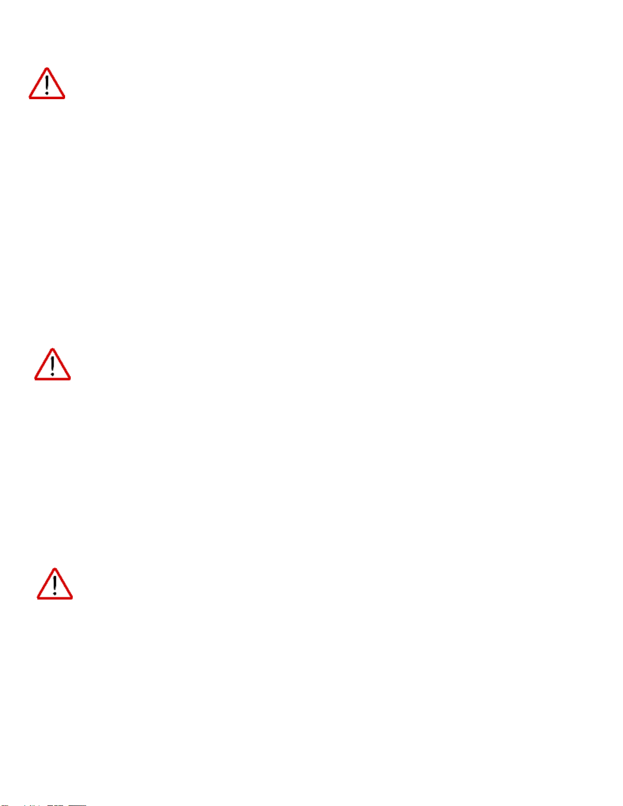
The RPS is a fully-automatic, self-regulating, high-efficiency power system. Once
connected to solar panels and loads (power consuming devices), the RPS will optimize
its charge cycle, preventing over-charging and over-discharging the battery. It will also
automatically re-enable the AC Power Outlets once the batteries have been sufficiently
recharged, minimizing the impact of potential power interruptions (even though your
fridge may lose power it will be restored once solar charging has brought the battery
back up to an operational voltage).
6
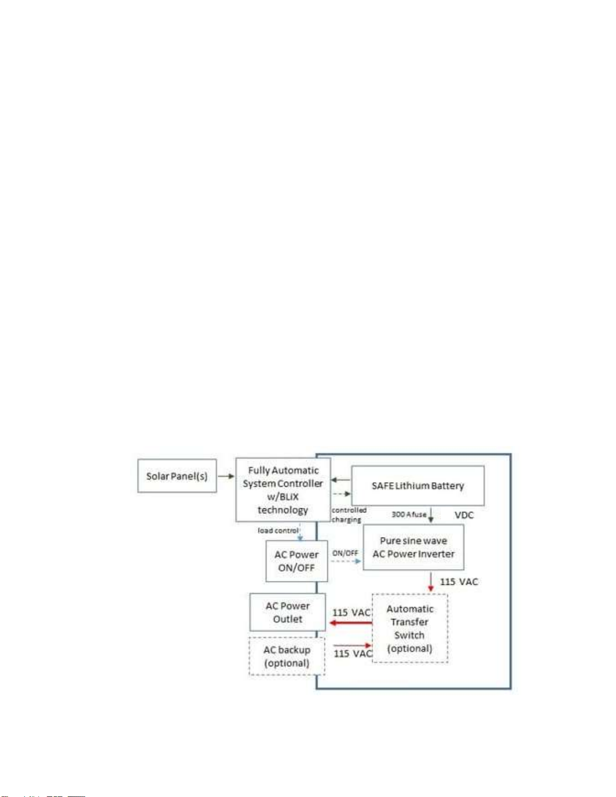
FEATURES
FRONT
CONTROLLER
CONTROLLER
MASTER
R SIDE
MAX Solar
Panel input for
24V system is
800W per
CONTROLLER,
1600W total
AC POWER
OUTLET
% Battery
Charge Meter
Utility Power
Inlet for
Automatic
Transfer Switch
(option)
BACK
AC
IN
BOTTOM
PORT for
75A 24V DC
Connector (to
Battery Pack)
System Enable
Switch
R SIDE
L SIDE
L SIDE
Grounding
Lug
7
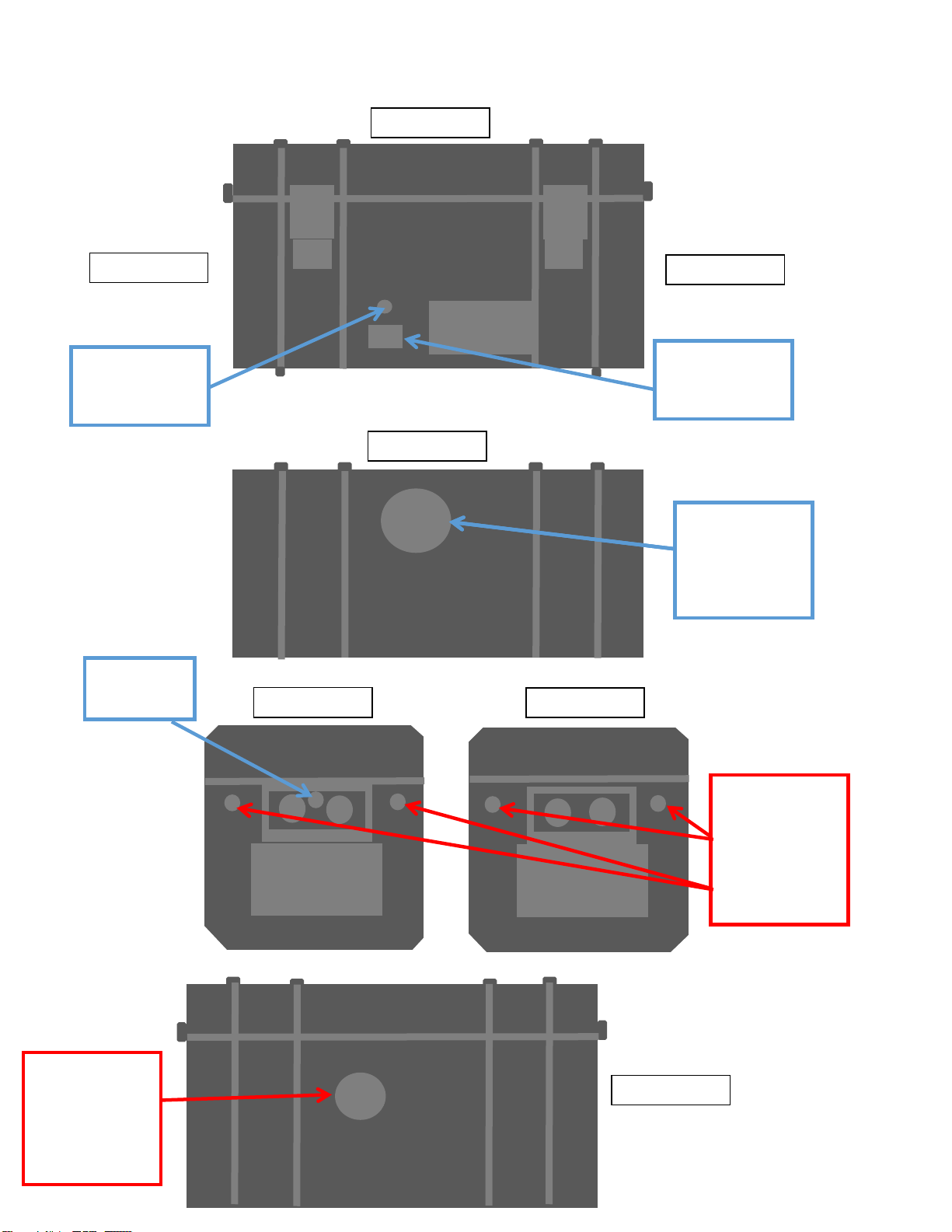
SET-UP
Battery Pack
TOP
FRONT
BACK
PORT for
75A 24V DC
Connector (to
RPS)
L SIDE
R SIDE
L SIDE
BOTTOM
8
SET-UP
Connect the (optional) Battery Pack at least 24 hours before operating the RPS to
allow the batteries to equalize.
1. Place the Battery Pack 8-10 inches away from a wall.
2. Place the RPS on top of the Battery Pack.
3. Tilt the RPS backwards so that the bottom is lifted away from the Battery
Pack top, this will expose the Case Plug and allow easy connection.
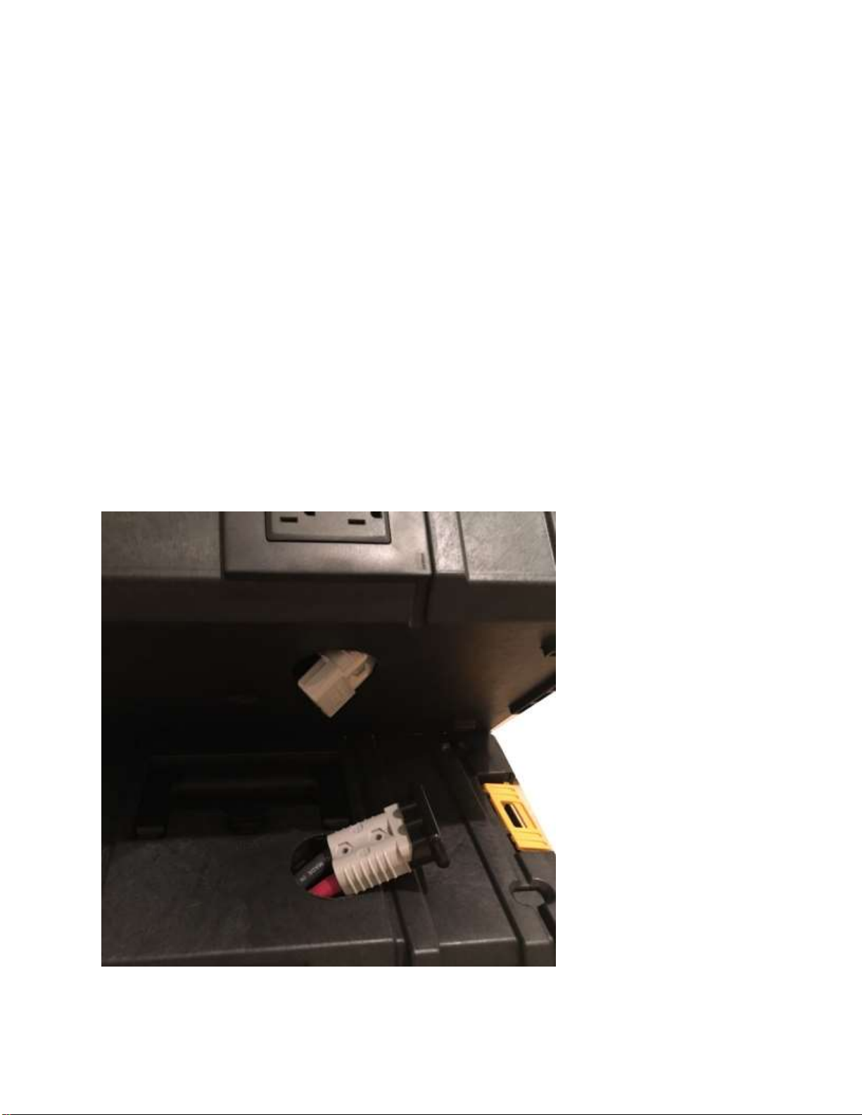
4. Remove the Case Plug from the RPS bottom to expose the High-Current
Connector. A flat blade screw driver can be used to aid removal of the Plug.
Note: The Battery Pack cable has a longer reach by design and also more
space inside the case for cable storage.

9
5. Pull the Connector from the Battery Pack and connect it to the Connector
from the bottom of the RPS. Make sure the connector is mated fully.
6. Gently lower the RPS onto the Battery Pack, allowing the connectors and
cable to recess into the Battery Pack.
10
7. Latch the side clamps to secure the cases to each other.
RPS SET-UP
Caution: Possible Damage to RPS Controllers when connecting Solar
1-Use a 30A fuse at each positive MC-4 input to the RPS to minimize damage to
the RPS from a power surge from the solar panels.
2-Only connect the solar panel cables to the RPS when the panels are not in direct
sunlight. Connecting before dawn or after sunrise is preferable. Connecting the
solar panels to the RPS while they are in sunlight will damage the Controllers due
to a high current pulse.
1. Identify a suitable, indoor, flat location for the RPS that is dry and well-
ventilated. Only operate the RPS while it is flat on the ground. Tilting the RPS
will impede cooling.

11
2. Install the solar panel frames. Ground any metal frames to prevent static
buildup. Also ground the RPS using the Grounding Lug on the right side of the
Case. A grounding rod can be used for this purpose.
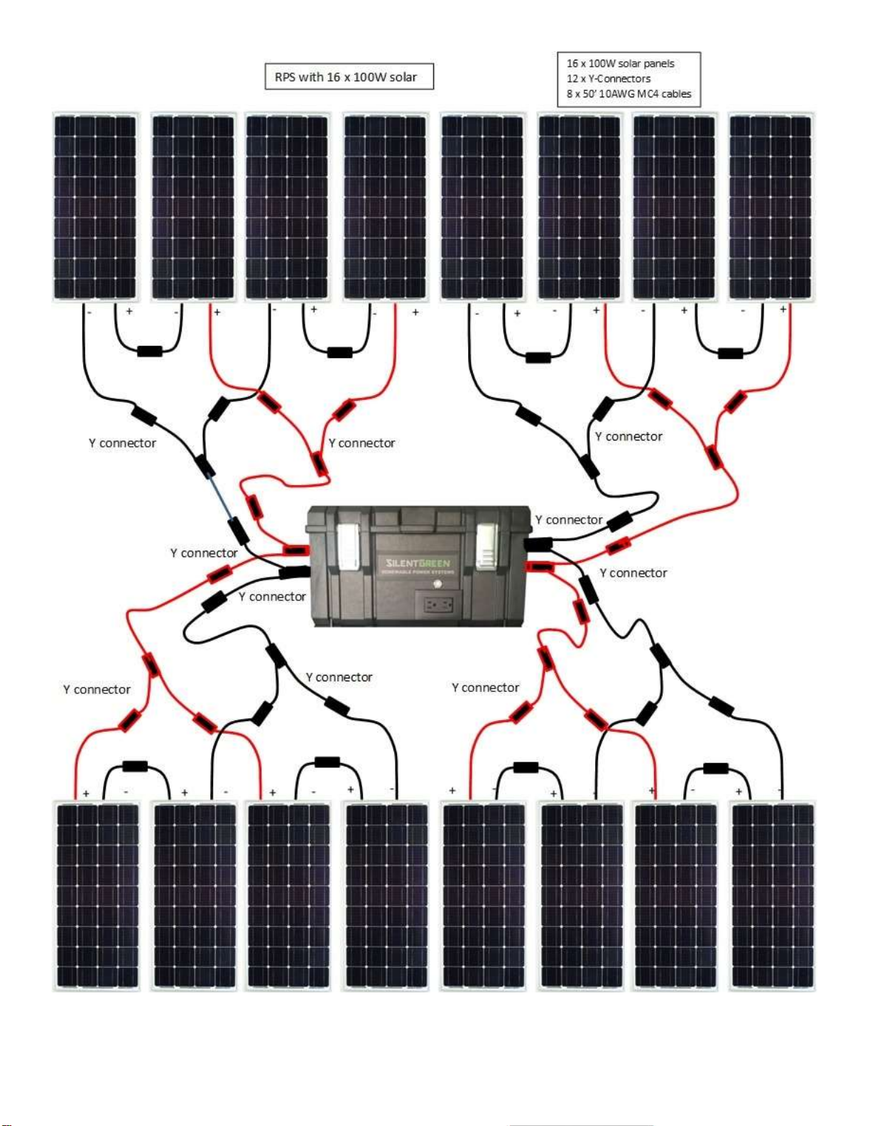
3. Connect the solar panels to the y connectors and then to the cables.
4. Run the cables from the solar panel array to the RPS. Make sure to take
sufficient precautions to protect the cable from weather and pests.
5. Connect the solar panels (up to 800 W per Controller).
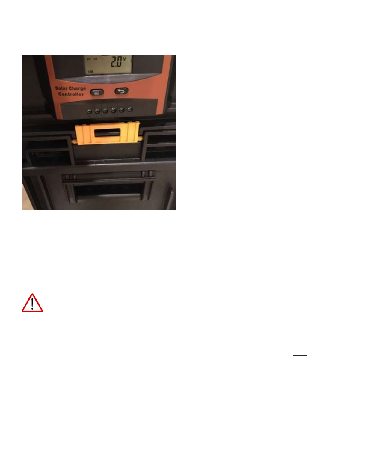
6. Enable the RPS by depressing the 'System Enable' Switch. If the battery
charge is within the safe charge limits the switch will light indicating
renewable power is available.
System Enable Switch
7. Connect equipment/devices (2000 W max.) to the RPS.
8. Monitor the % Battery Charge over time to determine if the amount of
power you are using is at a sustainable level. If power consumption remains
higher than the system can support, consider installing a second RPS or
replacing devices with more efficient types (e.g LED lights).
% Battery Charge Meter
12
System Controllers
The System Controller Displays cycle continuously to show: Battery Voltage, Solar
Panel Voltage, Load Current (ignore), Solar Charge Current, Temperature in
degrees Celsius.
The Controller on the RIGHT side (when facing the front of the RPS) is the MASTER
CONTROLLER. It controls the System Enable Switch light and actives/deactivates
the AC Outlet depending on the battery voltage. The AC Outlet is ON when the
System Enable Switch light is ON (green).
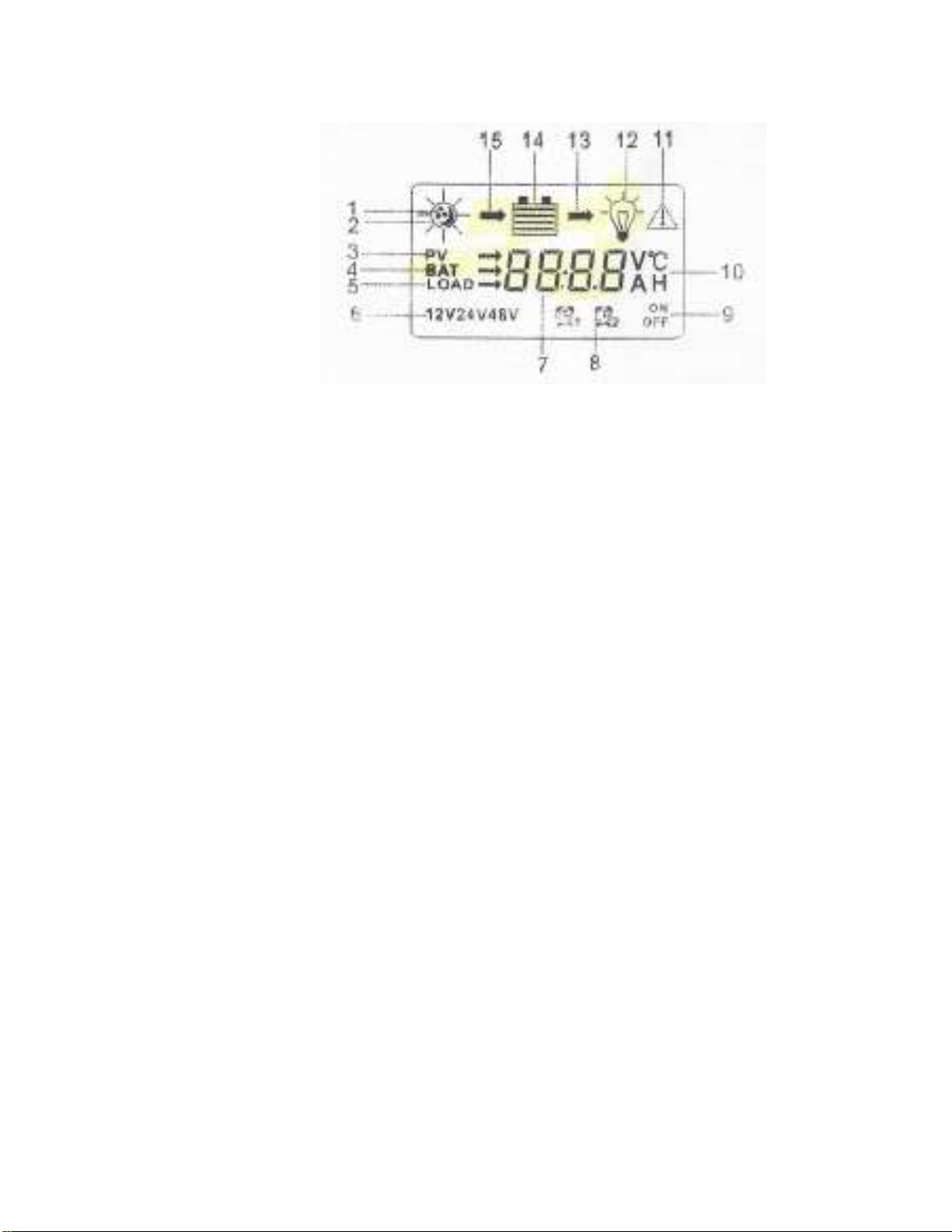
Display:
1&2-Day/Night (Day indicated when solar panel input detected)
3 - PV (solar panel input voltage displayed)
4 - BAT (battery voltage displayed)
13 - output arrow (battery within normal operating range)
15- input arrow (solar panels are charging the battery)
Buttons:
LEFT (menu) button
RIGHT (return arrow) button

13
Press the LEFT button on the CONTROLLER to show the accumulated Charge
Current in Ah. Sum both CONTROLLER displays for total solar input.
14

15

16
17
OPERATION
! WARNING! Shock hazard. Risk of injury to persons.
The RPS generates high AC voltage which can cause injury or death. Only a
qualified electrician should open the RPS for servicing.
WARNING! Shock hazard. Risk of injury to persons.
To avoid the possibility of electrical shock, make sure all AC electrical cords
connected to the RPS are in good condition.
WARNING: Explosion or fire hazard. Risk of injury to persons.’
Do not operate the RSG in areas that may contain explosive gas.
CAUTION! Possible Damage to RPS
Locate the RPS in a cool, dry location. Do not block the Vents as they are used to
cool the inverter. Provide at least 1 foot of clearance between the cooling vents
and any obstruction. The RPS operates most efficiently at room temperature
(around 78 F).
Operating Range
Controller Voltage Approximate Battery Charge
26.4 90% Upper Battery Voltage -Solar Charging Disabled
26.2 80%
26.0 70%
25.6 60%
25.4 50%
25.0 40%
24.8 30% AC inverter/AC Outlet re-enabled
24.6 20%
24.2 10% Lower Battery Voltage –AC inverter disabled
18
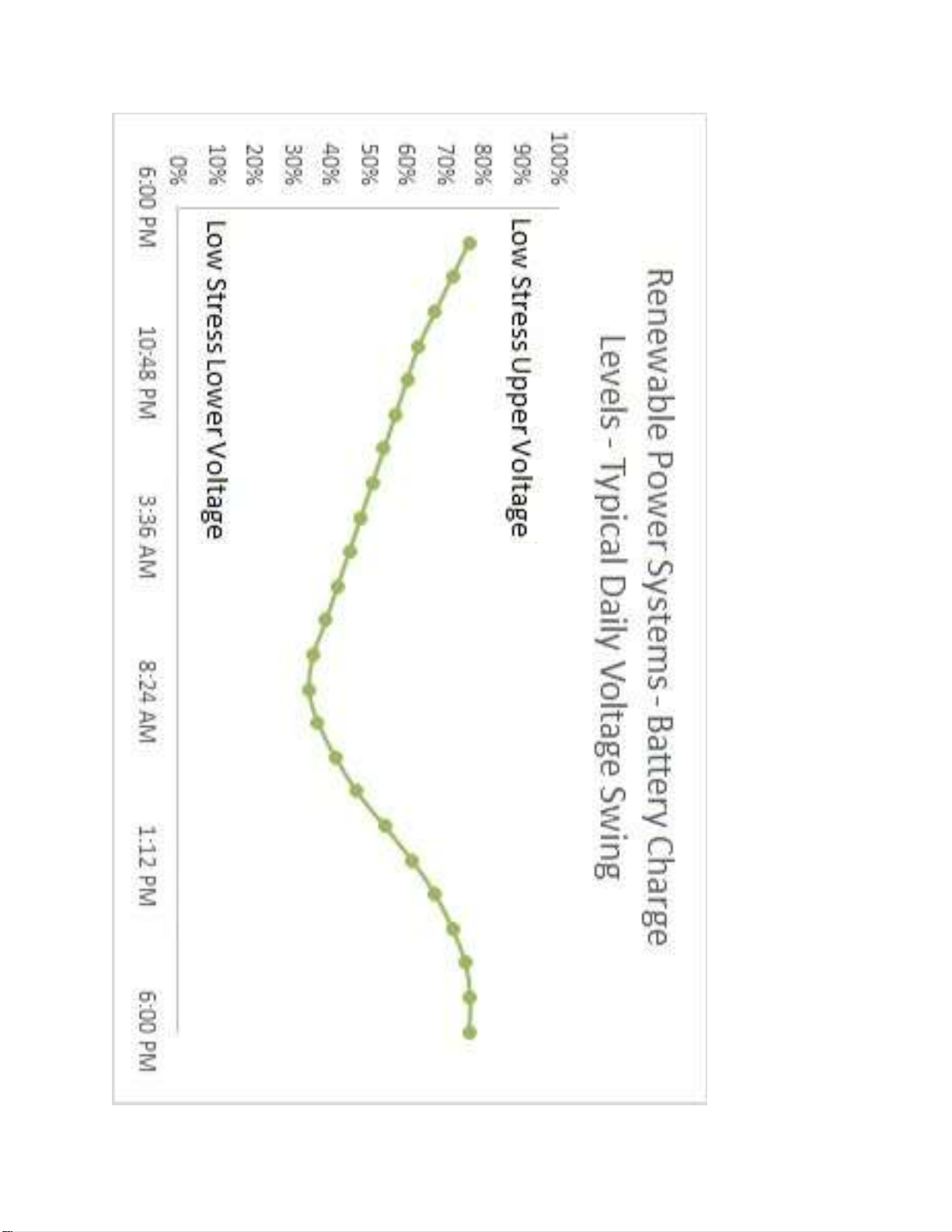
Maximum RPS Battery Voltage swing when system is ‘sustainable’

19
The RPS will provide renewable power continuously providing the available energy
IN is equal or greater than the energy OUT.
It is suggested that the first few weeks of operation of each season be recorded
from sunrise (typically the lowest daily voltage) to sunset (typically the highest
daily voltage) to determine sustainable system levels.
Time PV Voltage Battery Voltage
Sunrise
+2 hrs
+4 hrs
+6 hrs
+8 hrs
+10 hrs
+12 hrs
Sunset
The system is sustainable (able to provide purely ‘renewable’ power) when the
Battery Voltage at sunrise is consistently above the battery cutoff voltage
(approximately 10-15% charge level).
If the System Voltage is below the sustainable voltage level (where the system
turns itself off) consider reducing the equipment load on the RPS, add a Battery
Pack, or another RPS.
If the System Voltage cannot support the energy needs during sunlight hours,
consider reducing the equipment loads, or add another RPS.

20
Emergency Power
If AC Power is required after the RPS disables the AC Outlet, it is possible to
override the battery life extension feature (BLiX) by pressing the RIGHT button on
the RIGHT Controller for one second. This will override the Controller and run the
battery to 20 V at which time the inverter will alarm and then self-power down. It
is important that the battery be recharged as soon as possible to prevent
permanent damage.
MAINTENANCE
Controller terminals (bottom of each Controller) –occasionally check for tightness
(careful not to overtighten)
Cooling vents (top sides of Case) –occasionally check that vents are clear to allow
proper cooling
System Test
‘System Enable’ switch should be ON (depressed). On the Master Controller (right
side of RPS when looking at the front), press the RIGHT button for 1 second and
release, press the RIGHT button again and release. If the RPS is operating properly,
the ‘System Enable’switch light should toggle on and off with each press.
Table of contents
Popular Batteries Pack manuals by other brands


plenti SOLAR
plenti SOLAR Asgoft ASE-1000 user manual

Meec tools
Meec tools 021614 operating instructions

Harris Battery
Harris Battery TRACTION PACK Configuration and Operating Instructions

Enerdrive
Enerdrive EPL-100AH-12v-BATT owner's manual

RIDGID
RIDGID R84008 Operation manual

XOLTA
XOLTA BAT-79 user manual