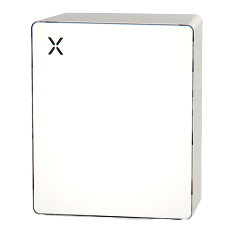
XOLTA BAT-79 User manual

Advanced energy storage system for
renewable energy and grid support applications
BAT-79 USER MANUAL
XOLTA OUTDOOR BATTERY ENERGY STORAGE SYSTEM
© 2021 by XOLTA

© 2021 by XOLTA
TABLE OF CONTENTS
1. Safety information and legal terms
1.1 Document purpose and structure ....................................................................................................................................3
1.2 Important safety Instructions ...........................................................................................................................................3
1.3 Actions in case of emergency situations ........................................................................................................................4
1.4 XOLTAcertiedinstallers..................................................................................................................................................6
1.5 Safedisposaloflithium-ionbatteries..............................................................................................................................6
1.6 Disclaimer..........................................................................................................................................................................6
1.7 Legal ..................................................................................................................................................................................6
1.8 Copyright ...........................................................................................................................................................................6
1.9 Void of warranty ................................................................................................................................................................7
1.10 Abbreviations ....................................................................................................................................................................7
XOLTA Battery Energy Storage System Overview
2.1 Introduction .......................................................................................................................................................................8
2.2 Hardware description .......................................................................................................................................................9
2.3 System safety ..................................................................................................................................................................10
2.3.1 Safety measures ..................................................................................................................................................10
2.3.2 InternalelectricalschemeoftheXOLTAoutdoorBESS ....................................................................................11
2.4 Keyspecications...........................................................................................................................................................12
3. XOLTA Battery Energy Storage System
3.1 Deliveryinspection..........................................................................................................................................................12
3.2 Location requirements ....................................................................................................................................................13
3.3 Installationprocedure.....................................................................................................................................................13
3.3.1Electricalrequirements........................................................................................................................................13
3.3.2Installationoverview............................................................................................................................................14
3.4 System operation ............................................................................................................................................................18
3.5 Maintenance requirements ............................................................................................................................................18
4. XOLTA Battery System functionality
4.1 Operating modes .............................................................................................................................................................19
4.1.1Maximizingsolarself-consumption ...................................................................................................................19
4.1.2Externalcontrol.....................................................................................................................................................20
4.1.3Gridvoltagesupport ............................................................................................................................................20
4.1.4Loadfollowing......................................................................................................................................................21
4.2 Sitecontrollerstatemachine .........................................................................................................................................21
4.2.1 SC States ..............................................................................................................................................................21
4.2.2TransitionalSequences ........................................................................................................................................23
4.3 XOLTA outdoor BESS monitoring ...................................................................................................................................23
5. Web API
5.1 WebAPI ...........................................................................................................................................................................24

© 2021 by XOLTA 3
1 SAFETY INFORMATION AND LEGAL TERMS:
1.1 Document purpose and structure
The purpose of this manual is to provide the user of the XOLTA Outdoor Battery Energy Storage System
(BESS) with an overview of system installation, functionality and operation.
The document is organized as follows:
Chapter 1 sets out important safety information, what to do in emergency situations and a list of abbreviations.
Chapter 2 gives a brief introduction to the XOLTA outdoor BESS system and describes its main features and key
specicationparameters.SafetymeasuresandprotectionschemesusedintheXOLTAoutdoorBESSare
also described.
Chapter 3 deals with system installation, maintenance and location requirements. Liability limitations are also mentioned.
Chapter 4 describes currently available XOLTA outdoor BESS operating modes and operating states.
Chapter 5 provides a list of telemetry signals accessible via the Web API.
1.2 Important safety instructions
TheXOLTAoutdoorBESSinstallationandservicingshouldonlybeperformedbyXOLTAcertiedinstallers.
Inconsequence,XOLTAprovidesnoliabilityforpropertydamageorinjurycausedbysystemmodication
orrepairsperformedbyunqualiedpersonnelorfailuretofollowthefollowingimportantsafetyinstructions.
The safety instructions have been divided into:
WARNING - indicates a dangerous situation which, if not avoided, could result in death or injury.
CAUTION - indicates a situation where damage to the equipment or injury may occur.
IMPORTANT SAFETY INSTRUCTIONS
Read the entire document carefully before installing or using XOLTA outdoor BESS.
RISK OF EXPLOSION:
Do not apply any external force to the XOLTA outdoor BESS.
Avoid physical damage to the battery. Keep the XOLTA outdoor BESS away from where it may accidentally
be physically damaged.
DonotdisposeoftheXOLTAoutdoorBESSinre.
RISK OF FIRE:
Keepsystemawayfromammableobjectsandheatsources.
Do not expose the battery system to temperatures in excess of 50°C.
RISK OF ELECTRICAL SHOCK:
There are high voltages present on AC and DC cables. There is a risk of death of serious injury due to electric
shock. Report any external cable/wire damage to XOLTA or local XOLTA system installer. Do not touch
uninsulated wires.

© 2021 by XOLTA
4
Never use a system if it is defective, damaged or broken.
Never attempt to disassemble, repair, modify the product or use it in any way other than as described in this
manual.RepairsorreplacementofcomponentsmustonlybeperformedbyaXOLTAcertiedtechnician.
NeverimmersetheXOLTAoutdoorBESSinwaterorotheruids.
RISK OF DAMAGE:
Do not expose the battery system to temperatures below -25°C or in excess of 50°C
Do not place any objects on top of the XOLTA BESS. It might lead to improper product operation or problems
with thermal management.
OTHER PRECAUTIONS:
The product should not be used for any purpose other than described in this manual.
Unpleasant smell might indicate electrolyte leakage from battery cell(s). In this case, switch the system off
and contact your XOLTA system supplier immediately. Ventilate the room if possible and avoid inhaling the odor.
The XOLTA outdoor BESS is heavy. Suitable lifting equipment is necessary.
Do not paint any part of the product.
For long term storage (longer than 1 month), the product should be charged to 40% SoC and then disconnected
from the grid. Observe warranty conditions.
The product must be disposed of according to local regulations.
1.3 ACTIONS in case of emergency situations
The XOLTA outdoor BESS is designed to be very safe. It monitors essential parameters of the battery system and
protects the battery from damage. The main battery safety measures are presented in Table 1.1 below.
Table 1.1:
List of main safety
measures in XOLTA
outdoor BESS
State of the art battery cells with excellent safety performance
State of the art battery management system (BMS) assuring over/under voltage and
over/under temperature monitoring for each individual battery cell
Redundant battery cut-off relay controlled by BMS
Temperature sensors monitoring battery system temperature
Active battery current control depending on battery cells temperature, voltage and state
of charge (SoC)
System diagnostics, error handling and automatic grid connection/disconnection
controlled by the site controller
Battery air humidity monitoring and condensation prevention system
AC and DC protective fuses

© 2021 by XOLTA 5
Despite all these built-in safety measures, emergency situations can still occur. In such emergencies, the
actions to take are as follows:
LEAKAGE
The battery pack might leak toxic electrolyte. Electrolyte is corrosive and odorous.
ACTION
• Avoid any contact with the leaking liquid or gas.
– In case of electrolyte inhalation - contact medical help.
– In case of electrolyte contact with skin - wash thoroughly with water and soap and contact medical
help.
– In case of electrolyte contact with eyes - rinse eyes with water for 15 minutes and contact medical
help.
– In case of electrolyte ingestion - force vomiting and contact medical help.
• Do not enter the room, if installed inside.
• Ventilate the room if possible.
• Contact your XOLTA system supplier.
FIRE
Firemayoccurduetomechanicaldamageorexternalsourcesofheatandre.Hazardousfumessuchas
carbondioxide,carbonmonoxideandhydrocarbonsareemittedduringbatteryres.
ACTION
• Disconnect the power from the battery system (if possible without getting too close to the battery and
without inhaling fumes).
• Nevertrytoextinguishabatteryreyourself.Ifbatterycellscatchre,thenonlyqualiedreghting
personnelwithappropriateprotectiveequipmentshouldattempttoextinguishthere.Keepawayfrom
batteryreandcontactreghters.
• Ifcomponentsotherthanbatterycellscatchre,thenABCorcarbondioxideextinguishercanbeusedto
extinguishthere.
• Keepawayfromthebatteryandcontactemergencyreghters.
IMMERSION IN WATER
Immersing the XOLTA outdoor BESS in water risks causing a short-circuit and damage to the battery system.
ACTION
• Do not try to access the XOLTA outdoor BESS.
• Disconnect the power (if possible without getting too close to the battery).
• Neveruseaoodedbatterysystemagain.
• Keep away from the battery and contact your XOLTA system supplier.

© 2021 by XOLTA
6
DAMAGED BATTERY
Any sign of mechanical damage or abnormal behavior of the battery system or its peripheral components
should be treated with extreme caution.
ACTION
• Never use a damaged battery system again.
• Disconnect the power.
• Keep away from the battery and contact your XOLTA system supplier.
1.4XOLTAcertiedinstallers
XOLTA provides appropriate training to installation technicians for XOLTA systems.
TheXOLTAoutdoorBESSmustonlybeinstalledandcommissionedbyXOLTAcertiedinstallers.Contact
XOLTAforalistofavailableXOLTAcertiedinstallers.
1.5SafedisposalofLithium-ionbatteries
Lithium-ion batteries must be treated as hazardous waste and not be disposed of with regular waste.
A XOLTA battery which has reached the end of its functional life can be returned to the seller that originally
sold the battery or to the dealer of a new industrial battery.
1.6Disclaimer
We have taken every precaution to ensure that all information provided in this manual is correct and up to
date.However,weassumenoresponsibilityfordamagetopersonsandpropertyarisingasaresultoffollowing
recommendations and/or procedures described in this manual. Furthermore, we assume no responsibility
for any infringements of rights of third parties which may result from the use of this manual.
1.7Legal
The system was designed to assure that an installed XOLTA outdoor BESS and all its associated function-
alitiesbehavesafelyunderthepredenedoperatingconditions.However,please,readallsectionsdescribing
safety issues and precautions carefully before installation, operation, or performing service work on a XOLTA
outdoor BESS. Failure to do so could result in reduced system performance, damage to the system, personal
injury or even death.
1.8Copyright
This document and all information contained in the XOLTA User Manual are copyright 2021 by Lithium
Balance A/S. All rights reserved. Lithium Balance reserves the right to make changes to the products described
in this manual at any time without notice. This manual may be photocopied or otherwise distributed only to
the extent that is necessary for the correct operation and installation of XOLTA outdoor BESS.

© 2021 by XOLTA 7
1.9 Void of warranty
XOLTA does not assume any direct or indirect liability for any damage or loss caused if:
• The product covered is not continuously connected to the internet via LAN cable, meaning that XOLTA
cannot monitor the performance of said product;
• The product covered has not been stored, transported, set up or installed in an appropriate and professional
manner in accordance with technical standards and regulations, in accordance with the relevant installation
manual of the product or the instructions of XOLTA;
• The product covered has been operated contrary to its intended use or contrary to the instructions in the
relevant installation manual;
• The product covered was out of service for a continuous period of more than six months after the initial
installation due to the fault of the Purchaser;
• The product covered has not been serviced properly and professionally according to technical standards
or XOLTA’s maintenance instructions;
• Theproductcoveredhasbeenexposed,eventemporarily,tovibrationsthateveninsignicantlyexceed
the usual extent of vibrations caused by transport and installation;
• The product covered has been improperly altered or otherwise tampered with by the Purchaser or any
third party;
• An overvoltage has occurred in the power grid to which the product covered is connected;
• Theproductcoveredhasbeenexposedtoforcemajeure(inparticularlightning,re,earthquakeornatural
disaster) or harmful environmental conditions such as air pollution, salt water or sulphur corrosion;
NOTE! Always refer to the Terms and Conditions document delivered by XOLTA for warranty conditions.
1.10Abbreviations
Table 1.2:
List of abbreviations
used in this XOLTA
User Manual
BESS Battery Energy Storage System
BMS Battery Management System
BoL Beginning of Life
BPU Battery Protection Unit - a unit containing switches and fuses for battery protection
CAN Controller Area Network - Serial communication protocol developed by Bosch
CMU Cell Monitoring Unit of nBMS
DoD Depth of Discharge
EoL End of Life
ESS Energy Storage System
GUI Graphical User Interface
MCU Main Control Unit of nBMS
MODBUS Serial communication protocol developed by Modicon
n-BMS Battery Management System from Lithium Balance A/S
NTC NegativeTemperatureCoefcientthermistor
PCS Power Conditioning System
POR Power on Reset
PV Photovoltaic
SC Site Controller
SoC State-of-Charge
TCO Total Cost of Ownership
TMS Thermal Management System

© 2021 by XOLTA
8
2 XOLTA BATTERY ENERGY STORAGE SYSTEM OVERVIEW:
2.1 Introduction
The XOLTA outdoor BESS is a modular, cloud-connected multipurpose stationary energy storage system.
The BESS was designed for a wide range of ambient temperature conditions which makes it suitable for
outdoor installation without any additional enclosure. The system is designed for various operation modes
(applications) which will be further described in Chapter 4.
The main features of the XOLTA outdoor BESS are:
• PLUG AND PLAY: Simple installation and commissioning. The system requires grid connection, internet
and electric meter connections.
• ALL IN ONE: All components of the system are integrated into a single cabinet. This includes the battery
cells, the power conditioning system (PCS), the thermal management system (TMS), the battery management
system (BMS), the multi battery rack control system and the energy management system.
• OUTDOOR OPERATION CAPABILITY: The mechanical casing of the system was designed to be effective
up to enclosure rating IP55 (dust and water jet ingress).
• MODULARITY:Thestoragesystempowerandenergycanbeexpandedandtailoredtospecicneeds.Intotal,
up to 32 XOLTA battery racks can be connected and operated in parallel providing up to 1MW and 2.5MWh.
• MULTIPURPOSE: The system is designed for various applications, from the integration of renewable energy
(e.g. increasing renewable self-consumption) up to various grid support applications (e.g. frequency and
voltage support).
• XOLTA CLOUD CONNECTION: The system is integrated with the XOLTA Cloud. It allows for system monitoring,
advanced control, data acquisition, and data storage.
• SAFETY: The system is designed to offer exceptionally high operational safety. For example, the system is
ttedwithstate-of-the-artbatterysystems,multi-layerandredundantprotectionsystems,LithiumBalance’s
battery management system (BMS) which assure maximal system safety under various operating conditions.
• LOWTOTALCOSTOFOWNERSHIP:Thisisachievedbyveryhighsystemround-tripefciency,lowstandby
losses, minimal operational and maintenance (O&M) cost and intelligent energy management.
• SITE CONTROLLER: This works as a multi battery rack control system and an energy management
system (EMS) which manages the entire XOLTA outdoor BESS. It provides charge/discharge power
management, monitoring to assure safe system operation, communication with all system peripherals
(e.g. the battery converter), data acquisition, communication with the XOLTA Cloud, system diagnostics
and error handling.
• THERMALMANAGEMENTSYSTEM:Simpleandefcientparallelcoolingsystem.
• PERIPHERALS:Possibilityofintegratingexternalenergymetersandother.

© 2021 by XOLTA 9
2.2 Hardware description
In this section, different hardware components of the XOLTA outdoor BESS are described. Figure 2.1 presents
the schematic drawing of the XOLTA outdoor BESS.
Each rack (battery cabinet) of the XOLTA outdoor BESS consists of eight serially connected battery packs
(as seen in Figure 2.1. All battery cells are protected by Lithium Balance’s n-BMS.
Figure 2.1:
Illustration of the
XOLTA outdoor
BESS hardware
components
Conv+
Conv-
Modbus TCP
L+N+PE
3L+PE
Ethernet
RJ45
Ethernet
RJ45
PCS
Conv+
Conv-
PCS
L+N+PE
3L+PE
BMS Low
BMS High
BMS Low
BMS High
BMS Low
BMS High
BMS Low
BMS High
BMS Low
BMS High
BMS Low
BMS High
BMS Low
BMS High
BMS Low
BMS High
Thermal management system
BESS Rack 1
BESS Rack N
+
-
-
+
+
-
-
+
-
+
+
-
+
-
-
+
BAT +
BAT +
PCS+
PCS-
PCS+
PCS-
BAT-
BAT +
Modbus TCP
Thermal management system
BMS Low
BMS High
BMS Low
BMS High
BMS Low
BMS High
BMS Low
BMS High
BMS Low
BMS High
BMS Low
BMS High
BMS Low
BMS High
BMS Low
BMS High
+
+
-
-
-
+
+
-
-
+
-
+
+
-
-
+
BAT-

© 2021 by XOLTA
10
Figure 2.2:
Illustration of the
XOLTA outdoor BESS
BPU front view
Each XOLTA outdoor BESS has a battery protection unit (BPU). Figure 2.2 is an illustration of the BPU
consisting of a communication section and a power section.
The site controller is installed in the BPU and is connected to the XOLTA Cloud using the Ethernet port shown
in Figure 2.2. The Ethernet port ensures communcation between neighboring racks if operating in unison.
The site controller communicates with Lithium Balance’s n-BMSs via the CAN bus.
The DB9 Modbus port is used for communication with peripherals (e.g. energy meters).
The RJ45 port marked SPI is used for communication between the n-BMS MCU and the n-BMS CMUs (which
are located in battery packs). An additional DB15 plug is used for activation of the thermal management
system, sensing outdoor air temperature, LED diodes control and communication with the humidity sensor-
The Modbus TCP port is used for communication with the power conditioning unit (PCS) and communication
with neighboring racks if operating in unison.
The BPU is powered by single phase 230V AC and is protected by a 1.5A fuse located in the power entry connector.
2.3 System safety
2.3.1 Safety measures
The XOLTA outdoor BESS is protected by Lithium Balance’s state of the art n-BMS. The system
monitors essential parameters of the battery system (cell voltage, current, temperature) to
ensure safe operation. The n-BMS also monitors the battery main parameters, e.g. State of Charge
(SoC) and performs battery cell balancing to ensure maximal energy utilization and performance.
The XOLTA outdoor BESS is equipped with a battery protection unit (BPU) which protects the
battery and the inverter from conditions which can be detrimental to the BESS. It includes redundant
relays controlled by the n-BMS and redundant fast battery fuses.
In addition, in order to assure system longevity and safe operation (maintaining correct operating
temperatures), each of the XOLTA outdoor BESS battery packs is equipped with 12 temperature
sensors (two sensors per battery module). These give a total of 96 temperature sensors per battery
rack. This number of temperature sensors allows for quick detection of local temperature gradients
and thus ensures system safety and equal cell performance during the system lifetime. Furthermore,
temperature sensors are located on all battery safety-related PCBs
The thermal performance of the XOLTA outdoor BESS is also monitored by the site controller and
allows for power/current derating whenever the cell temperature or the ambient temperature is
outside a strictly determined range. The site controller also allows for converter error handling and
automatic connection/disconnection of battery racks.
NTC, LED,
thermal
management
B AT-
BAT+
CAN
Modbus RTU
Power
entry port
SPI
INV+
INV-
Ethernet
Modbus TCP

© 2021 by XOLTA 11
The XOLTA outdoor BESS is also built with a special closed metal housing designed to prevent
repropagationbetweenbatterymodulesintheextremelyunlikelyeventofbatterythermalrunaway.
The cabinet is made of vandal resistant steel.
Finally, every Outdoor BESS can be equipped with an external emergency stop button which
disconnects the battery racks from the grid. The emergency stop button should be installed by an
electrician when connecting the BESS to the grid.
2.3.2 Internal electrical protection schematics of the XOLTA outdoor BESS
Figure 2.3 illustrates the protection scheme used inside the XOLTA outdoor BESS. The protection
schematics includes the following main components:
• one fast DC fuse located in each battery pack;
• two fast DC fuses located in the BPU;
• two DC relays controlled by the n-BMS (2 relays per BPU);
• one 1.5A AC relay for protection of the BPU power supply;
All metallic parts of the battery rack, battery packs and BPU are grounded.
In addition, all battery converters (PCS) provided as a part of the XOLTA outdoor BESS are grounded
and protected with AC fuses and DC and AC relays to ensure safe operation of the PCS.
Figure 2.3:
Illustration of
electrical protection
schematics used
for the XOLTA
outdoor BESS
F
200A
200A
200A
200A
200A
200A
200A
P+N+PE
3P+PE
P+N+PE
3P+PE
P+N+PE
3P+PE
200A
200A
200A
200A
200A
200A
200A
200A
BPU
BPU
BPU
PCS
30kVA
PCS
30kVA
PCS
30kVA
200A
200A
200A
200A
200A
200A
200A
200A
200A
200A
200A
200A
F
F
F
F
F
F
F
F
F
F
F
F
F
F
F
F
F
F
F
F
F
F
F
F
F
R
R
F
F
R
R
F
F
R
R
Rack 1 Rack 2 Rack N

© 2021 by XOLTA
12
2.4Keyspecications
KeyspecicationparametersoftheXOLTAoutdoorBESSareshowninthefollowingtable.
Table 2.1:
Key specications
for BAT-79
3 XOLTA BATTERY ENERGY STORAGE SYSTEM:
This part of the manual describes the installation and electrical connection of the XOLTA outdoor BESS
3.1Deliveryinspection
Each XOLTA outdoor BESS is delivered as a fully assembled cabinet on a single pallet. It has been carefully
checkedandtestedpriortoshipping.However,upondelivery,youshouldverifyvisuallythestateofpackaging
to make sure that it is in good condition. In case of any visual damage to the packaging, report it to XOLTA support.
3.2 Location requirements
• The XOLTA outdoor BESS is intended for outdoor use and is protected up to IP55;
• The ambient temperature in the installation place should be in the range of from -25 to maximum +35°C.
Thetemperaturerangecanbeexpandedwithactivecooling.Pleaseobservedatasheetspecications.
• Thesystemshouldnotbeimmersedinwaterorexposedtohightemperatures,amesorphysicalforce;
• No object should be placed on the top of the cabinet or within 0.5m of the top of cabinet;
• Thebatterycabinetsshouldbepermanentlyxedtotheground.Movingtheassembledbatteryracksis
strictly prohibited as this can damage the rack structure or the battery packs;
• All XOLTA outdoor BESS racks should be placed vertically and safely secured to the rack base and the
underlying foundation.
TECHNICALPROPERTIES
Power (charge/discharge) 30 kW standard, up to 80 kW
Nominal energy 79 kWh
Battery chemistry Li-ion NMC
Nominal battery voltage 700V DC
Battery voltage range 614-797 V DC
Grid connection voltage* 3 x 400V AC
Batterysystemefciency** 96,6%
Cooling standard Forced air cooling via heat exchanger (ambient temperature -25°C to 35°C)
Cooling active - optional Cooled by air conditioner (ambient temperature -25°C to 45°C)
Parallel coupling Ability to couple multiple racks in parallel
Cabinet Coated, vandal resilient steel enclosure
Dimensions D723mmxW846mmxH2180mm
Weight 1,083 kg. per rack
CE: Safety, health and environment
UN38.3classicationforsafetransportation
EN 61010-1: 2010 + A1: 2016 – safety req. battery systems
Standards EN 62477-1 (2012) safety req. for converters
EN 61439-1 (2011) inverter general construction and safety
EN/IEC 61000-6-2, industrial level – inverter EMC immunity
EN/ IEC 61000-6-4, class A – inverter EMC emission
Protection rating IP55
Expected life time 15 years
Performance warranty 10 years / 70%
*Higher voltage levels feasible with transformer, **100% DoD, 15kW round-trip efciency at 25°C

© 2021 by XOLTA 13
Figure 3.1:
Illustration of the
XOLTA outdoor BESS
battery racks
WARNING:
The XOLTA outdoor BESS should not be installed at the following locations:
• Areas prone to earthquakes
• Altitudes above 2000 meters above sea level; up to 4000 meters might be permissible but
will require converter’s maximum power derating
• Areaspronetoooding,openames,explosionandextremechangesofambienttemperature
3.3Installationprocedure
3.3.1 Electrical requirements
The XOLTA outdoor BESS has been designed for connection to low voltage three phase
400VAC50Hzelectricalgrids.However,thesystemcanalsobeconnectedtogridswithother
voltage levels (e.g. medium voltage level) if appropriate power/voltage conditioning units such
as power transformers are in place. Each XOLTA outdoor BESS cabinet (rack) has the following
electrical requirements:
• 3P+PE400VAC50Hzconnectionpoint;
• 1P+N+PE230VAC50Hzconnection.
Electrical installations and protection circuits must only be undertaken by an authorized electrician.
Figure 3.2 shows the installation and protection schematics for the 30kVA battery rack.

© 2021 by XOLTA
14
Figure 3.2:
Illustration of the
XOLTA outdoor BESS
electrical connection
and protection for
30kVA battery rack
The XOLTA outdoor BESS must be installed and commissioned by a XOLTA-trained technician. Any
subsequentchangesormodicationsperformedbyunauthorizedpersonnelarestrictlyprohibited
and could compromise safety.
3.3.2 Installation overview
3.3.2.1 Typical installation without solar panels
The block schematics in Fig 3.3 depict a typical installation of the XOLTA outdoor BESS unit
rack without solar panels.
Figure 3.3:
Typical XOLTA outdoor
BESS installation
without solar panels
Cloud
L2
L1
L3
N
PE
Grid
Meter
Ethernet
Switch
1P+N+PE
~230V, 2.5A
45 -
125A
2.5A -
10A
45 -
125A
2.5A -
10A
3P+PE
~400V, 43A
1P+N+PE
~230V, 2.5A
3P+PE
~400V, 43A
Other
Meters
(option)
PV
Meter
32 battery racks max
Ligthining protection
XOLTA BESS
Unit Rack
3 x 400VAC+PE, 45A
1 x 230VAC+N+PE, 10A
Main
Utility
Meter
X O LTA
Grid
Meter
Eth. Cable
Internet
Connection
Power
Grid
CTs
Eth.
Cable
Eth.
Cable
Meter
Supply
Fuse And
Switch
Cabinet
Eth.
Switch

© 2021 by XOLTA 15
3.3.2.2 Typical installation with solar panels
The block schematics in Fig. 3.4 depict a typical installation of the XOLTA outdoor BESS unit
rack with solar panels.
Figure 3.4:
Typical XOLTA outdoor
BESS installation
with solar panels
3.3.2.3 Grid feeding monitoring relay (optional)
In certain grids, there is a need to install a grid feeding monitoring relay between the battery
system and the public grid. The relay collects all relevant data regarding unusual status of
the public grid and automatically disconnects or reconnects the battery inverter. The grid
feedingmonitoringrelaymustbesetupaccordingtospeciclocalgridrequirements.
Ifthespecicgridparametermeasuredbythegridfeedingmonitoringrelayisnon-compliant,
a 24V signal is no longer provided to the inverter.
The grid feeding monitoring relay connects to the three phases (L1->L3) for voltage measure-
mentandutilizesthreecurrenttransformersformeasuringthecurrentowinthegrid.Current
transformers should be mounted on the three grid phases entering from the main grid meter.
IMPORTANT! The grid feeding monitoring relay must be installed to take measurements before any con-
sumption, i.e. right after the main utility meter.
A diagram of the grid feeding monitoring relay installation is shown in Fig. 3.5.
Depending on the manufacturer, the grid feeding monitoring relays may have different outputs
for driving the enable/disable signal for the inverter. Some of them may require an intermediate
small signal relay to handle the drive signal requirement.
The diagram of this only shows the principal connection diagram.
NOTE! Ifgridfeedingmonitoringrelayisnotneededinthespeciclocation,then24VDCfrompower
supply should be permanently connected to the inverter terminal 13 (Fig. 3.6).
Figure 3.5:
Diagram of grid
feeding monitoring
relay installation
PV Installation
XOLTA BESS
Unit Rack
3 x 400VAC+PE, 45A
1 x 230VAC+N+PE, 10A
Main
Utility
Meter
X O LTA
PV Meter
X O LTA
Grid
Meter
Eth. Cable
Internet
Connection
PV Inverter
Power
Grid
CTs
CTs
Eth. Cable
Eth. Cable
Eth. Cable
Meter Supply
Fuse And
Switch
Cabinet
Eth.
Switch
Grid Phase L3
Grid Phase L2
Grid Phase L1
Grid Null
W
V
U
NULL
24V DC to inverter
PE
Main
Utility
Meter
Voltage Input
Grid Feeding Monitoring
Relay (Optional)

© 2021 by XOLTA
16
The XOLTA BESS unit terminal connections (Fig. 3.6 and Fig. 3.7) are located at the bottom
oftherack.Removeallvescrewsholdingthelowerfrontplatetoaccesstheunitterminal
connections Fig. 3.7.
Figure 3.6:
Illustration of the
ve screws holding
the lower front plate
Figure 3.7:
Illustration of the
terminal functional
layout
Terminal 13

© 2021 by XOLTA 17
ThedetailedspecicationoftheunitterminalfunctionallayoutisprovidedinTable3.1.
Table 3.1:
Terminal
functional layout
3.3.2.5 Fuse and switch cabinet installation diagram
The XOLTA outdoor BESS rack installation procedure can be divided into the following steps:
A) Installation of the appropriate fuses with circuit breakers in the fuse and switch
electrical cabinet;
B) Connection of the cables to the unit terminal;
C) Installation of the required power meters (e.g. grid meter, PV meter, etc.);
D) Earthing of the battery rack (installation of the lightning protection);
E) Installation of the grid feeding monitoring relay (optional and dependent on the local
grid requirements);
All installation steps are visualized in Fig. 3.8.
Figure 3.8:
Diagram of the fuse
and switch cabinet
installation
TERMINAL TERMINAL1 TERMINAL2 TERMINAL3
Function Controller PE Controller Null Controller power
Voltagespecication PE N: AC NULL L: 240 VAC
Prefuse rating --------- --------- Prefuse: Min: 2.5 A
Conductor
cross section 1.5mm21.5mm21.5mm2
TERMINAL4 TERMINAL5 TERMINAL6 TERMINAL7
Inverter PE Inverter power L1 Inverter power L2 Inverter power L3
PE L1: 400 VAC L2: 400 VAC L3: 400 VAC
--------- Prefuse: Min: 45 A Prefuse: Min: 45 A Prefuse: Min: 45 A
16mm216mm216mm216mm2
(24V DC from grid
feeding monitoring
relay or from PS)
XOLTA BESS
FUSE AND SWITCH CABINET INSTALLATION
Terminal 13
XOLTA Rack Terminal 5, L1
XOLTA Rack Terminal 6, L2
XOLTA Rack Terminal 7, L3
Inverter Fuses With
Circuit Breaker
Controller Fuses With
Circuit Breaker
XOLTA Rack Terminal 1, PE
XOLTA Rack Terminal 3, N
XOLTA Rack Terminal 2, L
XOLTA Rack Terminal 4, PE
45A ≤ FUSE ≤ 125A
45A ≤ FUSE ≤ 125A
45A ≤ FUSE ≤ 125A
2.5A ≤ FUSE ≤ 10A
2.5A ≤ FUSE ≤ 10A
3 x CTs
Other
Installation
Consumers
PV
Meter
Internet
Connection
Ethernet Cable
C
E
W
V
U
N
PE
Main
Utility
Meter
Current INP
Voltage INP
Grid Feeding
Monitoring Relay
(Optional)
A
B
D
Battery Inverter
Battery
Protection
Unit (BPU)
X O LTA
Grid
Meter
Ethernet
Switch
3 x CTs
Lightning
Protection
Ethernet Cable
Ethernet Cable

© 2021 by XOLTA
18
3.3.2.6 Power components minimum rating
Table 3.2:
Power components
minimum rating
3.3.2.7 Recommended cable cross sections
The cables connecting the switch and fuse cabinet to the XOLTA outdoor BESS unit rack must
complywiththespecicationsinTable3.3.
Table 3.3:
Recommended cable
cross sections
3.3.2.8 Lightning protection
The XOLTA outdoor BESS is equipped with protective earthing (SAG 16mm2DIN Terminal
where the earth wire must be connected. The XOLTA rack is internally grounded with 10mm2
wire. The grounding resistance should follow local regulations.
3.4 System operation
The XOLTA outdoor BESS is intended to be operated from the XOLTA Cloud or via the Web API. System
operation is described in Chapter 5. Different operation modes and operation states of the XOLTA system
are described in Chapter 4.
Additionally, the operational state can be monitored by means of multicolored LED indicators that are located
at the top. The color codes of the LED indicators provide information about current operational state of the
XOLTA outdoor BESS. Details are provided in Table 3.4.
3.5 Maintenance requirements
WARNING:
Even a de-energized XOLTA outdoor BESS can cause injury or even death if operated by
unauthorized persons.
All maintenance must therefore be undertaken only by authorized personnel.
COMPONENT VOLTAGE RATING POWER/CURRENT RATING
Protection contractor 3 X 400 VAC >45 A
Protection
contractor coil 1 x 240 VAC <20 W
Protection
contractor SW* 240 VAC >2.5 A
Controller fuse* 240 VAC >2.5 A
Inverter main SW* 3 X 400 VAC >45A
Inverter fuses* 3 X 400 VAC >45A
CABLE USE CABLE CROSS
SECTION VOLTAGE RATING
Controller power L, N, PE to controller 3x1.5mm2750 V
Inverter power L1, L2, L3, PE to
inverter 4x16mm2750 V
Rack earthing (lightning protection) 1x16mm2Follow local
regulations
*Alternatively, a combined Switch/Automatic fuse with corresponding rating can be used

© 2021 by XOLTA 19
The XOLTA outdoor BESS was designed to require very little maintenance. Nevertheless, the following
maintenance is required to ensure smooth operation and longevity:
• The BESS converter must be maintained by checking for dust and cleaning when needed;
• For the XOLTA outdoor BESS, it is recommended that the following be undertaken every two years:
– check whether all fans are functioning correctly;
– visually inspect the condition of the power and communication cables, e.g. damage, dirt and dust, loose
connections, missing labels;
– visually check for the presence of any kind of leakage from the system;
– measure the system grounding resistance;
– check the tightness of the electrical and mechanical connections.
All system maintenance must be undertaken only by an authorized XOLTA technician.
Any abnormalities during system operation should be reported to XOLTA support. Spare parts should be
ordered from XOLTA support.
Table 3.4:
Explanation of the
LED indicator color
codes
4 XOLTA BATTERY SYSTEM FUNCTIONALITY:
4.1 Operating modes
TheXOLTAoutdoorBESScurrentlyoffersthefollowingoperatingmodesinordertotdifferentusers’needs.
4.1.1 Maximizing solar self-consumption
Maximizing self-consumption mode is the default operational mode of the XOLTA outdoor BESS. It is
designed to maximize the use of renewable energy, such as solar energy. As the generation of power
from solar energy often occurs at times of the day when residential households have low consumption
needs, the XOLTA outdoor BESS will store the excess solar energy during the day and release it when
user consumption exceeds the production of renewable energy production, as shown in Figure 4.1.
In the maximizing self-consumption mode, the battery will charge when there is excess solar energy
(solar production is higher than the demand) and discharge when the demand is higher than the solar
production
LED COLOR CODE OPERATION STATE PCS STATE BPU DC
RELAYS STATE
No color System is powered OFF OFF OFF
Blinking orange System in INITIALISATION or
START-UPorSHUTDOWNsequence ON/OFF ON/OFF
Solid orange System is in SLEEP state OFF ON
Blinking green System is in transitioning from SLEEP to
RUN state ON ON
Solid green System is in RUN state ON ON
Blinking blue System is in RUN state and is discharging ON ON
Blinking purple SystemisinRUNstateandCHARGING ON ON
Solid red System is in ERROR state OFF OFF

© 2021 by XOLTA
20
Figure 4.1:
Illustration of
maximizing self-
consumption mode
unctionality in the most
optimal situation
4.1.2 External control
The XOLTA outdoor BESS is able to react to power setpoints received from external systems. An
interface (web API) is provided which allows the user to decide the active power (P) and reactive power
(Q) controlling the battery system charge or discharge accordingly. This mode is ideal for users who
would like to develop their own control algorithm. It is also used for an installation functional check
when a XOLTA technician is doing on-site commissioning. There are two different formats of external
control:
• Single setpoint: System will work upon the single setpoint. The input can only be one value at a time.
• Schedule: System will work on a time schedule. It can be one value or a list of values.
The limitation of P-setpoints is constrained by the maximum apparent input/output power of the
inverter and the local grid capacity. Q-setpoints are limited by the power factor and the P measurement.
Positive P and Q-setpoint stand for charging and negative for discharging. A detailed XOLTA cloud
API instruction can be provided on request.
4.1.3 Grid voltage support
Grid voltage support is an operational mode intended to align with the distribution system operator’s
(DSO’s) requirements. Depending on the grid situation, the XOLTA System can offer different control
mechanisms to minimize the local grid voltage variations and meet the DSO requirements, as shown
in Figure 4.2 and 4.3.
Figure 4.2:
Exemplication of
the grid voltage
distribution with and
without grid voltage
support mode
E
nergy shi
f
ted by batter
y
Even
i
n
g
N
oonMorn
i
n
g
T
im
e
S
hi
ft
S
olar production
Consum
p
t
i
on
0.200
0.175
0.150
0.125
0.100
0.075
0.050
0.025
0.000 227.5 230.0 232.5 235.0
Voltage [V]
Phase 3
Phase 3 support
Probability density
237.5 240.0 242.5
Table of contents
Other XOLTA Batteries Pack manuals