Silicon Graphics Altix XE1300 User manual

SGI®Altix® XE1300 Cluster
Quick Reference Guide
007-4979-004

COPYRIGHT
© 2002-2008 SGI. All rights reserved; provided portions may be copyright in third parties, as indicated elsewhere herein. No permission is granted to copy,
distribute, or create derivative works from the contents of this electronic documentation in any manner, in whole or in part, without the prior written permission
of SGI.
LIMITED RIGHTS LEGEND
The electronic (software) version of this document was developed at private expense; if acquired under an agreement with the USA government or any
contractor thereto, it is acquired as “commercial computer software” subject to the provisions of its applicable license agreement, as specified in (a) 48 CFR
12.212 of the FAR; or, if acquired for Department of Defense units, (b) 48 CFR 227-7202 of the DoD FAR Supplement; or sections succeeding thereto.
Contractor/manufacturer is Silicon Graphics, Inc., 1140 East Arques Avenue, Sunnyvale, CA 94085–4602.
TRADEMARKS AND ATTRIBUTIONS
Silicon Graphics, SGI, Altix and the SGI logo are registered trademarks of SGI., in the United States and/or other countries worldwide.
Voltaire is a registered trademark of Voltaire Inc.
Scali Manage is a trademark of Scali AS, Oslo Norway.
SMC is a registered trademark of SMC Networks Inc.
Linux is a registered trademark of Linus Torvalds.
Unix is a registered trademark of the Open Group.
Windows is a registered trademark of Microsoft Corporation.
InfiniBand is a trademark of InfiniBand Trade Association.
PBS Professional is a trademark of Altair Grid Technologies, LLC.
All other trademarks mentioned herein are the property of their respective owners.

007-4979-004 iii
Record of Revision
Version Description
-001 March 2007
First publication.
-002 April 2007
Updated Scali Manage information to version 5.4.
-003 December 2007
Updates of Scali Manage information to version 5.5. and NIC1 IP address change
process re-written.
-004 March 2008
Updates for Altix XE250 head nodes and XE250 or XE320 compute nodes plus
Scali Manage version 5.6 information.


007-4979-004 v
Contents
1. SGI Altix XE1300 Cluster Quick-reference . . . . . . . . . . . . . . . . 1
Overview . . . . . . . . . . . . . . . . . . . . . . . . . 1
Site Plan Verification . . . . . . . . . . . . . . . . . . . . . . 2
Unpacking and Installing a Cluster Rack . . . . . . . . . . . . . . . . . 3
Booting the XE1300 Cluster . . . . . . . . . . . . . . . . . . . . 3
SGI Altix XE250 Head Node Front Controls and Indicators . . . . . . . . . . . 3
SGI Altix XE240 Head Node Front Controls and Indicators . . . . . . . . . . . 4
Compute Node Controls and Indicators . . . . . . . . . . . . . . . . 6
Cluster Configuration Overview . . . . . . . . . . . . . . . . . . . 7
Power Down the Cluster. . . . . . . . . . . . . . . . . . . . . . 12
Powering Off Manually . . . . . . . . . . . . . . . . . . . . . . 13
Ethernet Network Interface Card (NIC) Guidelines. . . . . . . . . . . . . . . 14
Cluster Management (Head Node) IP Addresses . . . . . . . . . . . . . . . 14
Changing the NIC1 (Customer Domain) IP Address . . . . . . . . . . . . . . 15
Cluster Compute Node IP Addresses . . . . . . . . . . . . . . . . . . 17
Switch Connect and IP Address . . . . . . . . . . . . . . . . . . . . 17
Web or Telnet Access to Maintenance Port on the Gigabit Ethernet Switch . . . . . . . 18
Web or Telnet Access to the Compute-Traffic Gigabit Ethernet Switch . . . . . . . . 18
Serial Access to the SMC Switch . . . . . . . . . . . . . . . . . . 19
InfiniBand Switch Connect and IP Address. . . . . . . . . . . . . . . . . 20
Web or Telnet Access to the InfiniBand Switch . . . . . . . . . . . . . . 20
Serial Access to the Switch . . . . . . . . . . . . . . . . . . . . 21
Using the 1U Console Option . . . . . . . . . . . . . . . . . . . . 22
Installing or Updating Software . . . . . . . . . . . . . . . . . . . . 23
Accessing BIOS Information . . . . . . . . . . . . . . . . . . . 23
Scali Manage Troubleshooting Tips. . . . . . . . . . . . . . . . . . . 24
NFS Quick Reference Points . . . . . . . . . . . . . . . . . . . . 25

vi 0074979-004
Contents
Related Publications . . . . . . . . . . . . . . . . . . . . . . . 26
Third-Party Clustering Documents . . . . . . . . . . . . . . . . . . . 28
Customer Service and Removing Parts . . . . . . . . . . . . . . . . . . 29
Contacting the SGI Customer Service Center . . . . . . . . . . . . . . . . 30
Cluster Administration Training from SGI . . . . . . . . . . . . . . . . . 30
2. Administrative Tips and Adding a Node . . . . . . . . . . . . . . . . . 31
Administrative Tips . . . . . . . . . . . . . . . . . . . . . . . 32
Start the Scali Manage GUI . . . . . . . . . . . . . . . . . . . . . 34
Head Node Information Screen . . . . . . . . . . . . . . . . . . . . 35
Adding a Node Starting from the Main GUI Screen . . . . . . . . . . . . . . . 36
Adding a Cluster Compute Node. . . . . . . . . . . . . . . . . . . . 37
Selecting the Server Type . . . . . . . . . . . . . . . . . . . . . 38
Network BMC Configuration . . . . . . . . . . . . . . . . . . . . 39
Select Preferred Operating System . . . . . . . . . . . . . . . . . . . 40
Node Network Configuration Screen . . . . . . . . . . . . . . . . . . 41
DNS and NTP Configuration Screen. . . . . . . . . . . . . . . . . . . 43
NIS Configuration Screen . . . . . . . . . . . . . . . . . . . . . 44
Scali Manage Options Screen . . . . . . . . . . . . . . . . . . . . 45
Configuration Setup Complete Screen . . . . . . . . . . . . . . . . . . 46
Checking the Log File Entries (Optional) . . . . . . . . . . . . . . . . . 47
Setting a Node Failure Alarm on Scali Manage . . . . . . . . . . . . . . . . 48
3. IPMI Commands Overview . . . . . . . . . . . . . . . . . . . . 53
User Administration . . . . . . . . . . . . . . . . . . . . . . . 54
Typical ipmitool Command Line . . . . . . . . . . . . . . . . . . 54
Adding a User to the BMC . . . . . . . . . . . . . . . . . . . . 54
Configuring a NIC . . . . . . . . . . . . . . . . . . . . . . . 54
Display a current LAN Configuration . . . . . . . . . . . . . . . . . 54
Configure a Static IP Address . . . . . . . . . . . . . . . . . . . 54
Serial-over-lan Commands . . . . . . . . . . . . . . . . . . . . . 55
Configuring SOL . . . . . . . . . . . . . . . . . . . . . . 55
Connecting to Node Console via SOL . . . . . . . . . . . . . . . . . 56
Deactivating an SOL Connection . . . . . . . . . . . . . . . . . . 56

Contents
007-4979-004 vii
Sensor commands . . . . . . . . . . . . . . . . . . . . . . . 56
Displaying all Objects in SDR . . . . . . . . . . . . . . . . . . . 56
Displaying all Sensors in the System . . . . . . . . . . . . . . . . . 56
Displaying an Individual Sensor . . . . . . . . . . . . . . . . . . 56
Chassis Commands . . . . . . . . . . . . . . . . . . . . . . . 57
Chassis Identify. . . . . . . . . . . . . . . . . . . . . . . 57
Controlling System Power . . . . . . . . . . . . . . . . . . . . 57
Changing System Boot Order . . . . . . . . . . . . . . . . . . . 57
SEL Commands. . . . . . . . . . . . . . . . . . . . . . . 57


007-4979-004 1
Chapter 1
1. SGI Altix XE1300 Cluster Quick-reference
Overview
Your SGI®Altix®XE1300 cluster system ships with a variety of hardware and software
documents in both hard copy and soft copy formats. Hard copy documents are in the packing box
and soft copy documents are located on your system hard disk in both
/usr/local/Factory-Install/Docs
and
/usr/local/Factory-Install/CFG
Additional third-party documentation may be shipped on removable media (CD/DVD) included
with your shipment.
This document is intended as an overview of some of the common operations that system
administrators may have to perform to set-up, boot, re-configure (upgrade) or troubleshoot the
SGI Altix XE1300 cluster.
The SGI Altix XE1300 cluster is a set of SGI Altix 1U-high servers (compute nodes), and one or
more SGI Altix 2U-high servers (head nodes) networked together, that can run parallel programs
using a message passing tool like the Message Passing Interface (MPI). Systems ordered prior to
the second quarter of 2008 generally use SGI Altix 310 servers as compute nodes and SGI Altix
XE240 servers as administrative head nodes. Most XE1300 clusters ordered in 2008 use SGI Altix
XE320 servers as compute nodes and SGI Altix XE250 servers as administrative head nodes.
Consult with your SGI support representative before swapping nodes between pre-existing and
newer clusters.
The XE1300 cluster is a distributed memory system as opposed to a shared memory system like
that used in the SGI Altix 450 or SGI Altix 4700 high-performance compute servers. Instead of
passing pointers into a shared virtual address space, parallel processes in an application pass
messages and each process has its own dedicated processor and address space. Just like a
multi-processor shared memory system, a cluster can be shared among multiple applications. For
instance, one application may run on 16 processors in the cluster while another application runs
on a different set of 8 processors. Very large clusters may run dozens of separate, independent
applications at the same time.
Typically, each process of an MPI job runs exclusively on a processor. Multiple processes can
share a single processor, through standard Linux context switching, but this can have a significant
effect on application performance. A parallel program can only finish when all of its sub-processes
have finished. If one process is delayed because it is sharing a processor and memory with another
application, then the entire parallel program is delayed. This gets slightly more complicated when

2007-4979-004
1: SGI Altix XE1300 Cluster Quick-reference
systems have multiple processors (and/or multiple cores) that share memory, but the basic rule is
that a process is run on a dedicated processor core.
These are the primary hardware component types in the rackmounted cluster:
• Head node(s)
(SGI Altix XE240 or XE250 2U-high servers)
• Compute nodes
(SGI Altix XE310 or XE320 1U-high servers)
• Network interconnect components
(Gigabit Ethernet switches, InfiniBand switches, PCI cards, and cables)
The head node is connected to the interconnect network and also to the “outside world”, typically
via the local area network (LAN). The head node is the point of submittal for all MPI application
runs in the cluster. An MPI job is started from the head node and the sub-processes are distributed
to the cluster compute nodes from the head node. The main process on the head node will wait for
the sub-processes to finish. For large clusters or clusters that run many MPI jobs, multiple head
nodes may be used to distribute the load.
The compute nodes are identical computing systems that run the primary processes of MPI
applications. These compute nodes are connected to each other through the interconnect network.
The network interconnect components are typically Gigabit Ethernet or InfiniBand. The MPI
messages are passed across this network between the processes. This compute node network does
not connect directly to the “outside world” because mixing external and internal cluster network
traffic could impact application performance.
Site Plan Verification
Ensure that all site requirements are met before you install and boot your system. If you have
questions about the site requirements or you would like to order full-size floor templates for your
Additional helpful site planning information can be found in the SGI Altix XE Cluster Site
Planning Guide, (P/N 007-5456-001).

Unpacking and Installing a Cluster Rack
007-4979-004 3
Unpacking and Installing a Cluster Rack
When your system is housed in a single rack, the cluster components come rackmounted and
cabled together and a document describing how to unpack and install the rack should be included
with the system. Refer to the SGI Altix XE System Rack Installation Instructions (P/N
007-4902-00x). Follow the instructions provided in that manual to safely and properly unpack and
install your rack system. Ensure all rack power distribution units are properly plugged in and the
circuit breakers are switched to (On). All units within the rack should be connected to power
before booting.
Multi-rack cluster systems require connection of special interconnect cables between racks. The
Manufacturing System Diagram document (P/N 007-4944-00x) shipped with your cluster system
describes the inter-rack cable connections. If you have arranged for SGI field personnel to install
the system rack(s), contact your service representative. After your cluster rack(s) are installed,
refer back to this guide to continue working with your SGI cluster system.
Booting the XE1300 Cluster
Power on any mass storage units attached to your cluster, then press the power button on the front
of the head node and let it fully boot. Repeat the process on all the other nodes (compute nodes)
in the cluster. See the applicable subsection for your system configuration.
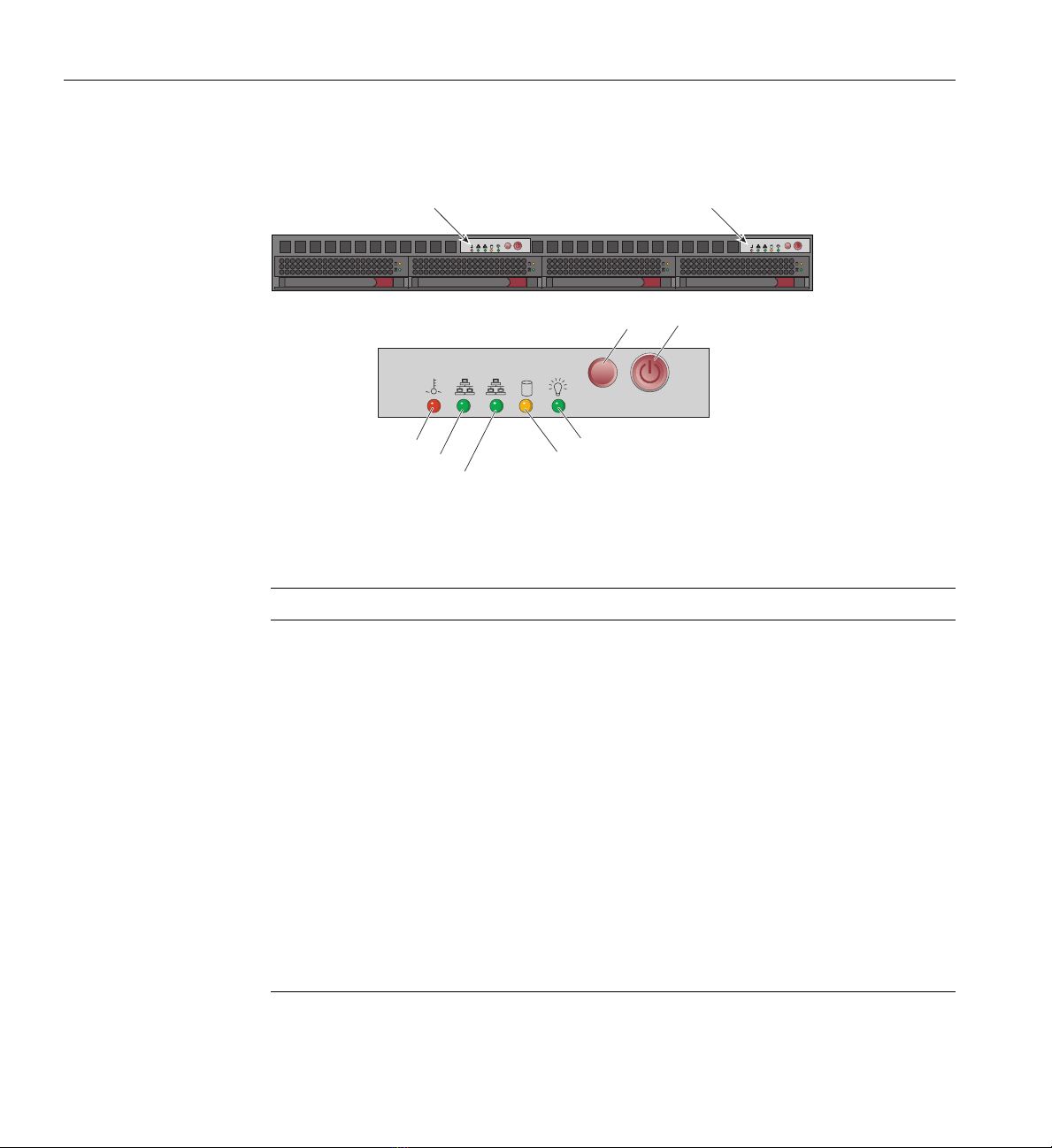
SGI Altix XE250 Head Node Front Controls and Indicators
The front control panel on the SGI Altix XE250 head node (see Figure 1-1) has six LED indicators
to the left of the power and reset buttons. The LEDs provide critical server related information.
RESET
21
Power
Reset
Power fail HDD
Overheat/Fan fail Power
NIC1/NIC2
Figure 1-1 SGI Altix XE250 Front Control Panel

4007-4979-004
1: SGI Altix XE1300 Cluster Quick-reference
•HDD: Channel activity for the hard disk drive (HDD). This light indicates drive activity on
the node board when flashing.
•NIC1/NIC2: Indicates network activity on the LAN1 or LAN2 interconnect when flashing.
•Overheat/Fan fail: When the Overheat/Fan Fail LED flashes, it indicates that a fan has
failed. When the Overheat/Fan Fail LED is on continuously, it indicates that an overheat
condition has occurred, which may be caused by cables obstructing the airflow in the
system, covers removed, or the ambient room temperature being too warm.
•Power Fail: Indicates power is being supplied to the system’s power supply unit. This LED
should normally be illuminated when the system is operating.
SGI Altix XE240 Head Node Front Controls and Indicators
AF000030
L JK
H
I
BA F GEDC
Figure 1-2 SGI Altix XE240 Head Node Controls and Indicators
Table 1-1 SGI Altix XE240 Head Node Controls and Indicators
Callout Feature Description
ANIC 2 Activity LED Continuous green light indicates a link between the system and the
network interface card to which it is connected.
BNIC 1 Activity LED Blinking green light indicates network interface card 1 activity
CPower/Sleep button Powers the system On/Off. Puts the system in an ACPI sleep state.

Booting the XE1300 Cluster
007-4979-004 5
DPower/Sleep LED Constant green light indicates the system has power applied to it.
Blinking green indicates the system is in S1 sleep state.
No light indicates the power is off or is in ACPI S4 or S5 state.
EHard disk drive
activity LED
Blinking green light indicates hard disk activity (SAS or SATA).
Unlighted LED indicates no hard disk drive activity.
FSystem status LED Solid green indicates normal operation. Blinking amber indicates
degraded performance. Solid amber indicates a critical or
non-recoverable condition. No light indicates the system POST is
running or the system is off.
GSystem
Identification LED
Solid blue indicates system identification is active.
No light indicates system identification is not active.
HSystem
Identification
Button/LED
Press this button once to activate the System Identification LED. Press
the button again to de-activate the System Identification LED. Solid
blue indicates system identification is active.No light indicates system
identification is not active.
IReset Button Reboots and initializes the server.
JUSB 2.0 port Allows attachment of a USB component to the front of the node.
KNMI button Puts the node in a halt-state for diagnostic purposes.
LVideo Port Allows attachment of a video monitor to the front of the chassis.
Note the front and rear video ports cannot be used at the same time.
Table 1-1 (continued) SGI Altix XE240 Head Node Controls and Indicators
Callout Feature Description
6007-4979-004
1: SGI Altix XE1300 Cluster Quick-reference
Compute Node Controls and Indicators
PowerRESET
RESET
21
Overheat/Fan fail LED
NIC 2 activity LED
NIC 1 activity LED
HDD activity LED
Power LED
RESET
RESET
Control panel:
Node board 2
Control panel:
Node board 1
Figure 1-3 SGI Altix XE310/XE320 Compute Node Controls and Indicators
Table 1-2 SGI Altix XE310/XE320 Compute Node Controls and Indicators
Feature Description
RESET Press the reset button to reboot only the node board controlled by that control panel.
POWER Press power button to apply or remove power only to the node board controlled by
that control panel. Pressing this button removes the main power but keeps standby
power supplied to the node board.
Overheat/Fan fail When the Overheat/Fan Fail LED flashes, it indicates that a fan has failed. When the
Overheat/Fan Fail LED is on continuously, it indicates that an overheat condition has
occurred, which may be caused by cables obstructing the airflow in the system or the
ambient room temperature being too warm.
NIC2 Indicates network activity on LAN2 when flashing.
NIC1 Indicates network activity on LAN1 when flashing.
HDD Channel activity for the hard disk drive (HDD). This light indicates SATA drive
activity on the node board when flashing.
Power Indicates power is being supplied to the system’s power supply unit. This LED
should normally be illuminated when the system is operating.

Cluster Configuration Overview
007-4979-004 7
Cluster Configuration Overview
The following four figures are intended to represent the general types of cluster configurations
used with SGI XE1300 systems.
Note: These configuration drawings are for informational purposes only and are not meant to
represent any specific cluster system.
Figure 1-4 on page 8 diagrams a basic Gigabit Ethernet configuration using a single Ethernet
switch for node-to-node communication.
Figure 1-5 on page 9 illustrates a dual-switch cluster configuration with one switch handling MPI
traffic and the other used for basic cluster administration and communication.
Figure 1-6 on page 10 is an example configuration using one Ethernet switch for general
administration and one InfiniBand switch for MPI traffic.
Figure 1-7 on page 11 shows a configuration with one Ethernet switch used for administration,
one Ethernet switch for NAS, and an Infiniband switch used for handling MPI traffic.

1U slide out
console
Remote workstation
monitor
Customer Ethernet
Base Gigabit Ethernet
switch for Admin.
Standard
RJ-45
twisted-pair
cable
Head Node
Compute Node
Compute Node
Compute Node
8007-4979-004
1: SGI Altix XE1300 Cluster Quick-reference
Figure 1-4 Basic Cluster Configuration Example Using a Single Ethernet Switch

1U slide out
console
Remote workstation
monitor
Customer Ethernet
Base Gigabit Ethernet
switch for Admin.
Standard
RJ-45
twisted-pair
cable
Head Node
Compute Node
Compute Node
Compute Node
GigE PCI card
Base Gigabit Ethern
et
switch (MPI)
Cluster Configuration Overview
007-4979-004 9
Figure 1-5 Dual-Ethernet Switch Based Cluster Example

Base Gigabit Ethernet
switch for Admin.
InfiniBand
switch (MPI)
1U slide out
console Remote workstation
monitor
Standard
RJ-45
twisted-pair
cable
InfiniBand cables
Customer Ethernet
Head Node
Compute Node
Compute Node
Compute Node
InfiniBand
PCI card
10 007-4979-004
1: SGI Altix XE1300 Cluster Quick-reference
Figure 1-6 Single Ethernet and Single InfiniBand Switch Configuration Example

Base Gigabit Ethernet
switch for Admin.
InfiniBand
switch (MPI)
1U slide out
console Remote workstation
monitor
Standard
RJ-45
twisted-pair
cable
InfiniBand cables
Customer Ethernet
Gigabit Ethernet
switch for NAS
NAS
Head Node
Compute Node
Compute Node
Compute Node
Standard
RJ-45
twisted-pair
cable
InfiniBand
PCI card
Cluster Configuration Overview
007-4979-004 11
Figure 1-7 Dual Ethernet Plus Infiniband Switch Cluster Configuration Example

12 007-4979-004
1: SGI Altix XE1300 Cluster Quick-reference
Power Down the Cluster
Note: You can also use the baseboard management controller (BMC) interface to perform power
management and other administrative functions. Refer to the Altix XE310 User’s Guide,
publication number 007-4960-00x, for more information about the BMC interface. See the SGI
Altix XE320 User’s Guide, publication number 007-5466-00x for information on its BMC.
You can use the Scali parallel shells tools suite to perform remote power management from the
head node. Login to the head node as root, and use the /opt/scali/sbin/power command
to manage the system.
#power -H
Usage:
/opt/scali/sbin/power [option] [nodelist <on|off|cycle|status>]
Example:
Use the following command to power cycle cluster nodes 001 through 032:
power cl1n[001-032] -cycle
If your cluster uses the Scali Manage administrative software (release 5.x.x), you can power-off
specific nodes or the entire system using the graphical user interface. Select Management
Menu>Power Mgt>Power Off. The compute nodes can be halted from the Scali GUI by
selecting the nodes and choosing “halt system” and “power down” from the System Management
menu. A command line interface is also available to power-on/off or check status.
Note: Refer to the Scali Manage User’s Guide for more information. You must have root
privileges to perform these types of tasks.
Table of contents
Other Silicon Graphics Network Hardware manuals


Popular Network Hardware manuals by other brands

HP
HP X1600 - StorageWorks Network Storage System 5.4TB SAS Model NAS... Release notes

National Instruments
National Instruments FieldPoint cFP-20 Series user manual

Toshiba
Toshiba MicroMAS installation guide

Comba Telecom
Comba Telecom ONU-HGU-F04P2T0W2N01 user manual

M86 Security
M86 Security R3000 Series Evaluation guide

IOGear
IOGear GWAVRB user manual


