Silitek SK-8810 User manual

User’s Manual
U
Us
se
er
r’
’s
s
M
Ma
an
nu
ua
al
l
FCC ID : GYUR95SK
Model :SK-8810
RF Wireless Keyboard
Department: Wireless BU
Date: July-14-2001

User’s Manual
RF WIRELESS KEYBOARD Page No: 1of 4
FEDERAL COMMUNICATIONS COMMISSION
This device complies with Part 15 of the FCC Rules. Operation is subject to the following
two conditions:(1) this device may not cause harmful interference, and (2) this device must
accept any interference received, including interference that may cause undesired
operation.
NOTE
This equipment has been tested and found to comply with the limits for a Class B digital
device, pursuant to Part 15 of the FCC Rules. These limits are designed to provide
reasonable protection. This equipment generates, uses and can radiated radio frequency
energy and, if not installed and used in accordance with the instructions, may cause harmful
interference to radio communications. However, there is no guarantee that interference will
not occur in a particular installation If this equipment does cause harmful interference to
radio or television reception, which can be determined by turning the equipment off and on,
the user is encouraged to try to correct the interference by one or more of the following
measures:
-Reorient or relocate the receiving antenna.
-Increase the separation between the equipment and receiver.
-Connect the equipment into an outlet on a circuit different from that to which the receiver is
connected.
-Consult the dealer or an experienced radio/TV technician for help.
Shielded interface cables must be used in order to comply with emission limits.
Changes or modifications not expressly approved by the party responsible for compliance
could void the user‘s authority to operate the equipment.

User’s Manual
RF WIRELESS KEYBOARD Page No: 2of 4
1. General
This Product Specification is for SK-8810, the product is composed of a 27MHz RF wireless
desk top PC keyboard and a PS2 dual function receiver.The receiver supports both keyboard
and pointing function.The keyboard includes eight easy access keys and a built-in I-Point
device supporting pointing function. The product package includes wireless keyboard and
receiver.
1.1 Main feature
The product provides 2 channels /16 ID operation to prevent frequency interference. The
receiver interface with both the wireless keyboard and pointing to the system through the
PS2 port.
The product set supports both keyboard and point device function..
There is a LED on the keyboard for the indication of low battery power, two LEDs on the
receiver for the indication of power and data receiving.
Achannel-selection button on Keyboard transmitter and receiver for channel setting
purpose.
1.2 Features of keyboard
uThis model contains special function keys. There is one LED on the keyboard for
battery low power indication.
uFour AA batteries are to be installed at the bottom of the keyboard for operation.
uThere is a Channel Selection button at the side of the keyboard near the hot keys row.

User’s Manual
RF WIRELESS KEYBOARD Page No: 3of 4
2 System Block Diagram
Functional Block diagram:
TX-Circuit
CPU
(4.912MHz,Inter
nal)
RF Signal
RX-Circuit CPU
(12MHz,Internal
)
PC Host
PS2 Interface
Low power indicator
Power indicator
Data indicator

User’s Manual
RF WIRELESS KEYBOARD Page No: 4of 4
3. Electrical Specification
3.1 Keyboard Transmitter
3.1.1 Operating voltage
The operating voltage range for keyboard is 4.5 ~ 5.2 Vdc. There are 4 AA batteries
providing 6.0V for operation, fed to keyboard via voltage regulator.
3.1.2 Current consumption
Typical current consumption is 30 mA, .Maximum at 50 mA
3.2 Receiver
3.2.1 Operating voltage
Voltage supplied to keyboard: 5+/-0.25 VDC
With ripple lower than 150mv, and capable of supply load current up to 100
mA with voltage drop less than 0.25 VDC
3.2.2 Current consumption
Under nominal 5 VDC power supplied, typical current
Consumption is 33 mA at normal operation, 60mA at maximum.
3.2.3 Pin outs of 6 pin PS2 min-DIN connector
Compatible with IBM PS2 spec.
3.2.4 LED indicators
There are two indicators(green) on the receiver: Receiving Data and Power. The
Data indicator will be ON only when data is receiving from the transmitter. The
Power will be ON only when the system is ON. During the Suspend and Sleep
modes, the Power LED will be OFF.
3.2.5 Cable
PS2 mini-DIN plug connector at two end of “Y” cable for both keyboard
and pointing device .

User’s Manual
RF WIRELESS KEYBOARD Page No: 5of 4
3.3 Operations
3.3.1 Battery removal
When the batteries are removed from the keyboard, the channel goes back
to its default setting on the keyboard while the channel in Receiver is no
change.
3.3.2 Default –Channel-setting (Channel Reset)
Procedure is as follows:
1. Press once on the Channel Selection button on Rx (see Note 1 below).
2. Press on the Channel Selection button on Tx (see Note 2 below).
Note 1: (on Receiver)
Press once to clear all channel and ID from the memory of EEPROM.
The LED on the Rx will then be ON and being ready to receive
setting information of channel and ID from the Tx.
Note 2: (on Keyboard)
uPress and hold the button for more than 3seconds: both channel
and ID go to Default. The LED on RX will be OFF after finish
receiving data from TX.
uIt can also be done by re-installing the batteries .
3.3.3 Channel change
Operated by following step :
1. Press once on the Channel Selection button on RX ,the LED at RX
will be ON.
2. Press on the Channel Selection button on TX ,the LED at RX will be
OFF after finish receiving data from TX.
The computer screen will display the Channel number
User’s Manual
RF WIRELESS KEYBOARD Page No: 6of 4
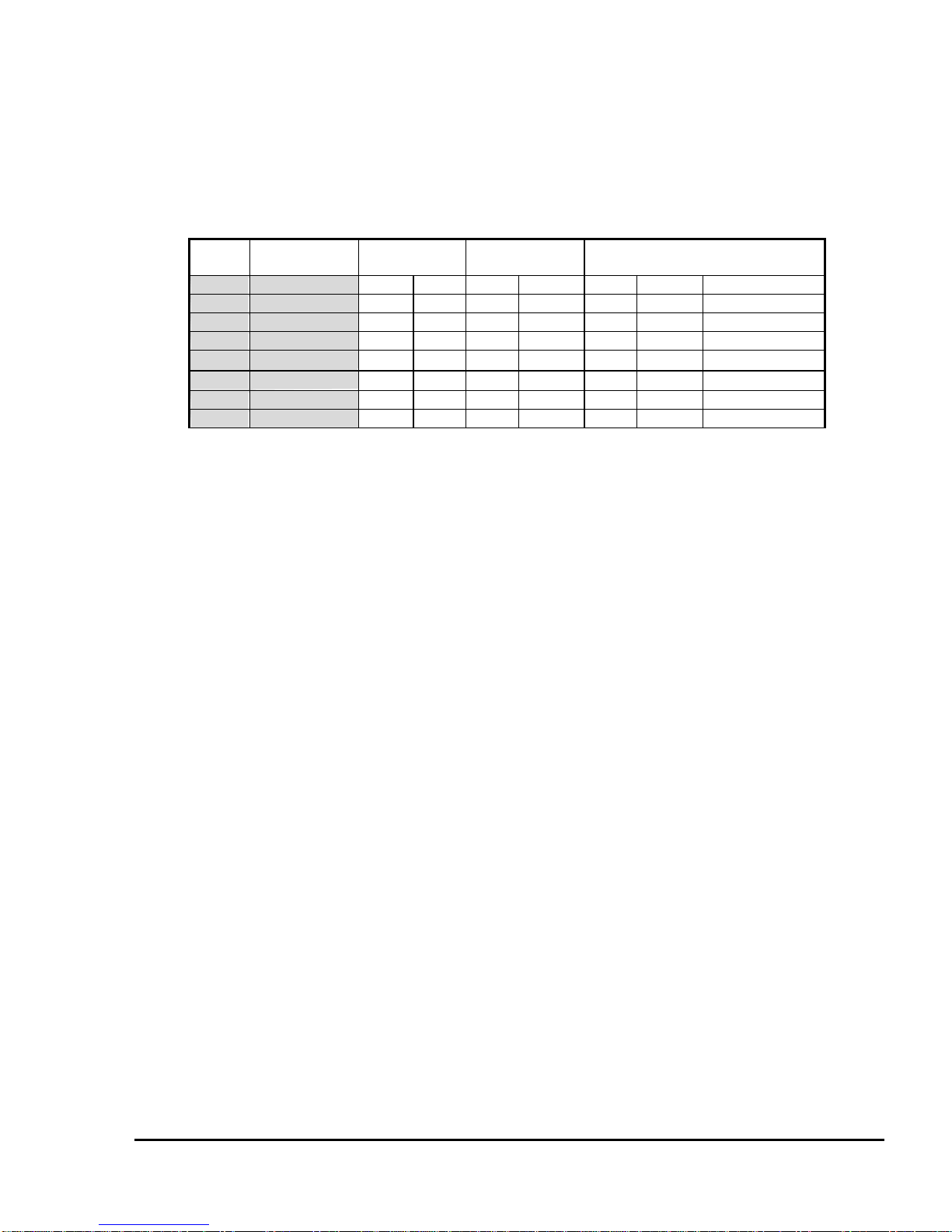
3.3.4 Easy Acess Key Code Table
All Easy Acess Keys are the use of reserved PS2 scan code for extension use.
There are listed by sequence below, it correspond to the easy access keys from left to right on
keyboard:
Key
Address
US Key
Assignment SCAN SET 1
Make Break
SCAN SET 2
Make Break SCAN SET 3
Make Break Attr.
66 M2 (Left)
E0 25
E0 A5
E0 42
E0 F0 42
9D F0 9D M/B
67 M3 E0 18
E0 98
E0 44
E0 F0 44
9F F0 9F M/B
65 M1 E0 17
E0 97
E0 43
E0 F0 43
98 F0 98 M/B
68 M4 E0 32
E0 B2
E0 3A
E0 F0 3A
97 F0 97 M/B
56 M13 E0 20
E0 A0
E0 23
E0 F0 23
9B F0 9B M/B
63 M14 E0 26
E0 A6
E0 4B
E0 F0 EB
9C F0 9C M/B
71 M7 E0 12
E0 92
E0 24
E0 F0 24
96 F0 96 M/B
73 M9 (Right) E0 24
E0 A4
E0 3B
E0 F0 3B
94 F0 94 M/B
Table of contents
Other Silitek Keyboard manuals


