Silver Marine Calypso 360 AL User manual
Calypso 360 AL
Calypso 420 AL
www.silvermarine.com
INSTRUCTION MANUAL.............................................1-13
MANUEL D’INSTRUCTION........................................15-27
ANWEISUNG HANDBUCH........................................29-41
INSTRUCTIE HANDBOEK.........................................43-55
MANUAL DE INSTRUCCIÓN.....................................57-69
BRUKSANVISNING..................................................71-83
GB
FR
DE
NL
ES
SE


CONTENTS
GENERAL INTRODUCTION......................................................................................................2
STRUCTURE TERMINOLOGY..................................................................................................3
TECHNICAL SPECIFICATIONS.................................................................................................3
PARTS TERMINOLOGY...........................................................................................................4
PACKING LIST........................................................................................................................5
INSTALLATION TIPS...............................................................................................................5
STEP ONE: STARTING UP...................................................................................................5
STEP TWO: ALUMINIUM BOARD, SEAT AND SEAT BAG ASSEMBLY...................................6
STEP THREE: FINISH INFLATION........................................................................................8
STEP FOUR: OAR ASSEMBLY.............................................................................................8
STEP FIVE: SELF-BAILING DRAIN VALVE...........................................................................8
MOTOR INSTALLATION...........................................................................................................9
DEFLATION AND DISASSEMBLY.............................................................................................9
PRESERVATION......................................................................................................................9
MAINTENANCE......................................................................................................................10
REPAIRING............................................................................................................................10
FOLDING & STORAGE...........................................................................................................12
OPERATION..........................................................................................................................12
ROWING..............................................................................................................................12
MOTORING & SAFETY.........................................................................................................12
TOWING...............................................................................................................................12
STABILITY AND BUOYANCY..............................................................................................12
TROUBLESHOOTING CHART.................................................................................................13
1
ENGLISH

GENERAL INTRODUCTION FOR THE OWNER’S MANUAL
This manual has been compiled to help you operate your craft with safety and pleasure. It contains
details of the craft, the equipment supplied and information on their operation. Please read it carefully
and familiarize yourself with the craft before using it.
This owner’s manual is not a course on boating safety or seamanship. If this is your first craft, or if you
are changing to a type of craft you are not familiar with, for your own comfort and safety, please ensure
that you obtain handling and operating experience before “assuming command” of the craft. Your dealer
or national sailing federation or yacht club will be pleased to advise you of local sea schools, or compe-
tent instructors.
Ensure that the anticipated wind and sea conditions will correspond to the design category of your craft,
and that you and your crew are able to handle the craft in these conditions.
Even when your boat is categorized for them, the sea and wind conditions corresponding to the design
categories A, B and C range from severe storm conditions for category A, to strong conditions for the top
of category C, open to the hazards of a freak wave or gust. These are therefore dangerous conditions,
where only a competent, fit and trained crew using a well maintained craft can satisfactorily operate.
This owner’s manual is not a detailed maintenance or trouble-shooting guide. In the case of difficulty,
refer to the safety characteristics of the craft shall be assessed, executed and documented by compe-
tent people. The boat builder cannot be held responsible for modifications that he has not approved.
In some countries, a driving license or authorizations are required, or specific regulations are in force.
Always maintain your craft properly and make allowance for any deterioration that might occur in time
as a result of heavy use or misuse of the craft.
Any craft, no matter how strong it may be, can be severely damaged if not used properly. This is not
compatible with safe boating. Always adjust the speed and direction of the craft to sea conditions.
All persons should wear a suitable buoyancy aid (life jacket/personal floatation device) when on deck.
Note that, in some countries, it is a legal requirement to wear a buoyancy aid that complies with their
national regulations at all times.
PLEASE KEEP THIS MANUAL IN A SECURE PLACE, AND HAND IT OVER TO THE NEW OWNER
WHEN YOU SELL THE CRAFT.
Thank you for choosing Silver Marine® inflatables. They are carefully handcrafted with polyester fabric
coated with PVC on both sides, and include a transom and molded floorboard system. This manual has
been compiled to help you achieve long term safe use, and pleasure from your Silver Marine®. Please
read it carefully and familiarize yourself with the craft before boating.
This boat is in compliance with the the Recreational Craft Directive 94/25/EC changed by the directive
2003/44/EC according to the design category C.
This craft is designed to operate in winds up to Beaufort force 6 and the associated wave heights
(significant wave height up to 2m). Such conditions may be encountered in exposed inland waters, in
estuaries, and in coastal waters in moderate weather conditions.
2

STRUCTURE TERMINOLOGY
BOATING TERMINOLOGY
1) Bow
2) Freeboard
3) Keel
4) Stern
5) Waterline
6) Forward
7) Aft
8) Beam
9) Transom
10) Length overall
11) Starboard side
12) Port side
4
1
25
3
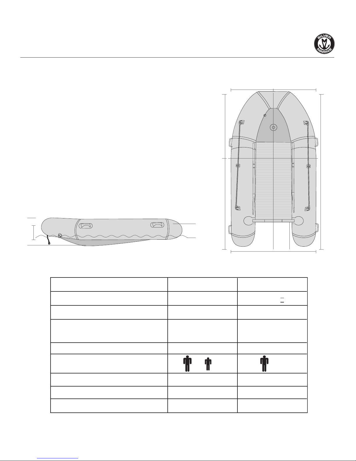
TECHNICAL SPECIFICATIONS
MODEL
STANDARD NO.
DESIGN CATEGORY
DIMENSIONS
(Inflated hull length x beam)
MAX. MOTOR POWER
MAX. PASSENGER CAPACITY
MAX. PAYLOAD
RECOMMENDED WORKING PRESSURE
WEIGHT
Calypso 360 AL
C, TYPE V
EN ISO6185-2:2001
11’9” x 5’9”
(3.59 x 1.76m)
20HP (14.7kw)
5 +1
1191lbs (540kg)
0.25 bar*
141lbs (64kg)
Calypso 420 AL
C, TYPE V
EN ISO6185-3:2001
14’ x 6’3”
(4.26 x 1.91m)
30HP (22.5kw)
7
1653lbs (750kg)
0.25 bar*
195lbs (89kg)
II
* Designed working pressure for each buoyancy chamber is 0.25 bar; must not to be less than 0.18 bar.
12 11
6
10
7
8
9
3

3.SAFETY GRAB
3.SAFETY GRAB
ROPE
ROPE
3.SAFETY GRAB
ROPE
4.RUBBER STRAKING
4.RUBBER STRAKING
4.RUBBER STRAKING
10.HI-QUALITY MATERIALS
10.HI-QUALITY MATERIALS
10.HI-QUALITY MATERIALS
9.RECESSED AIR VALVE
9.RECESSED AIR VALVE
9.RECESSED AIR VALVE
2.BENCH SEAT
2.BENCH SEAT
2.BENCH SEAT
8.ALUMINIUM DECK
8.ALUMINIUM DECK
8.ALUMINIUM DECK
5.OARS
5.OARS
5.OARS
1.D-TOWING RING
1.D-TOWING RING
1.D-TOWING RING
7.LIFTING HOLES IN TRANSOM
7.LIFTING HOLES IN TRANSOM
7.LIFTING HOLES IN TRANSOM
6.SELF-BAILING DRAIN VALVE
6.SELF-BAILING DRAIN VALVE
6.SELF-BAILING DRAIN VALVE
PARTS TERMINOLOGY
4
PACKING LIST
1) Calypso 360 AL:
Boat Hull, Oars, Foot Pump, Pressure Gauge, Wooden Seat, Docking Rope, Safety Grab Rope, 4
Screw Valves + 1 Drain Valve, Repair Kit and Carry Bag, 3 pieces Aluminum Boards, 1 piece Wooden
Board, 4 Pieces Stringer, Bench Bag, Front Storage Bag and Boat Cover.
2) Calypso 420 AL:
Boat Hull, Oars, Foot Pump, Pressure Gauge, Wooden Seat, Docking Rope, Safety Grab Rope, 5
Screw Valves + 1 Drain Valve, Repair Kit and Carry Bag, 3 pieces Aluminum Boards, 1 piece Wooden
Board, 4 Pieces Stringer, Bench Bag, Front Storage Bag and Boat Cover.
INSTALLATION TIPS
Tip 1: Make sure to tuck in the aluminum floor edge correctly into the aluminium stringers.
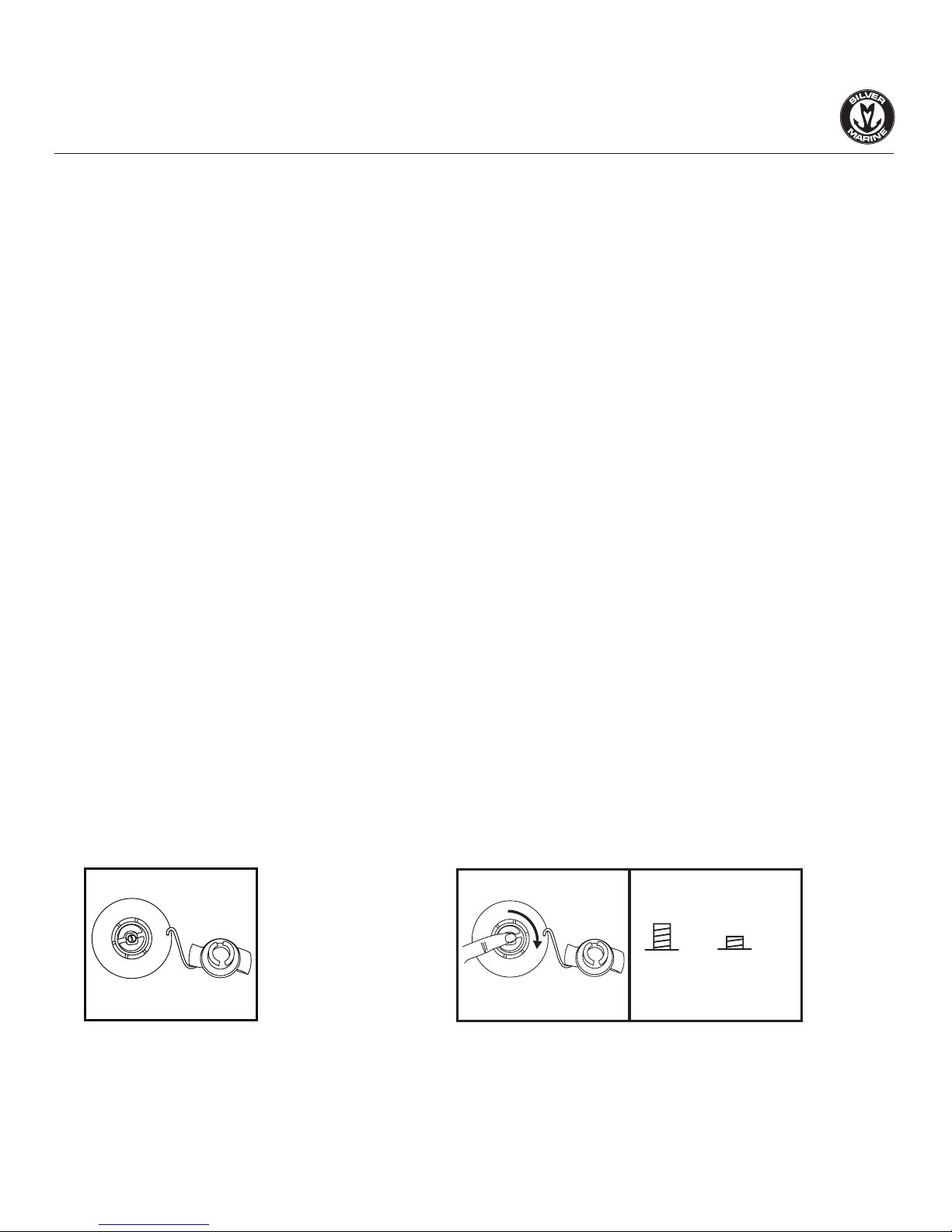
Tip 2: Make sure to press down and turn the pop-up spring valve 90 degrees before inflating. (The default
setting is for deflation.)
Tip 3: If using an electric pump, after tube inflation, use a foot pump to add a little more air to ensure
correct pressure.
Tip 4: In case the valve is loose, screw it tight with the black plastic wrench included in the accessories.
Tip 5: In case you find difficulty when installing the bench seat, put your knees on one of the inflated
tubes to add pressure to the bench handle.
HOW TO SET UP THE BOAT?
STEP ONE: STARTING UP
1. Unfold the hull
Clear a flat area (make sure it is clean and free of sharp objects). Remove the hull from box and take off
the plastic bag. Unroll the hull and lay it out flat.
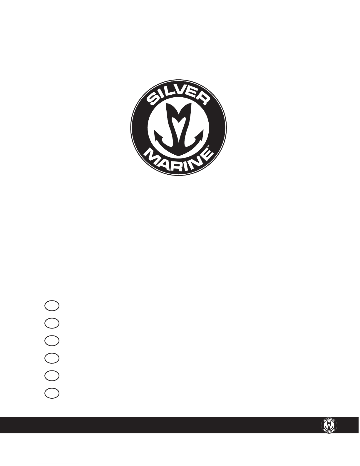
2. Screw Valve Installation
1
2.2
UP DOWN
(A) INFLATE (B) DEFLATE
2.1
PRESS AND TURN 90
1. Take off the top of the valve. (The valve
by default is at deflation position)
2. Pressing down the spring switch and turn it clockwise
by 90 degrees. Make sure the switch is popped up. Note:
To deflate, press the inner button at the center and turn
counterclockwise 90 degrees.
5
3. Inflate the chambers slightly.
At this time, we suggest first inflate the air chambers to about 10% (about 20 times by foot pump) of
their capacity so that the hull material does not stick to itself and the floorboards can be easily inserted.
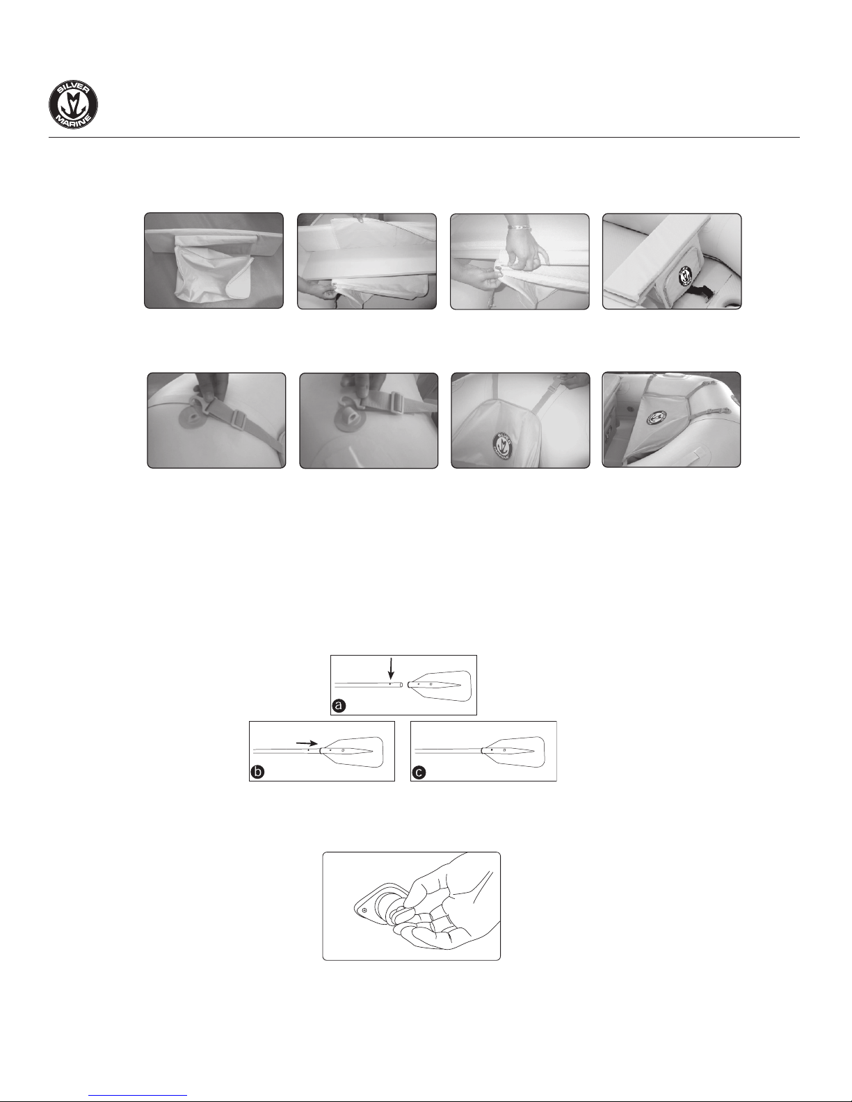
STEP TWO:
ALUMINIUM BOARD, SEAT AND SEAT BAG ASSEMBLY
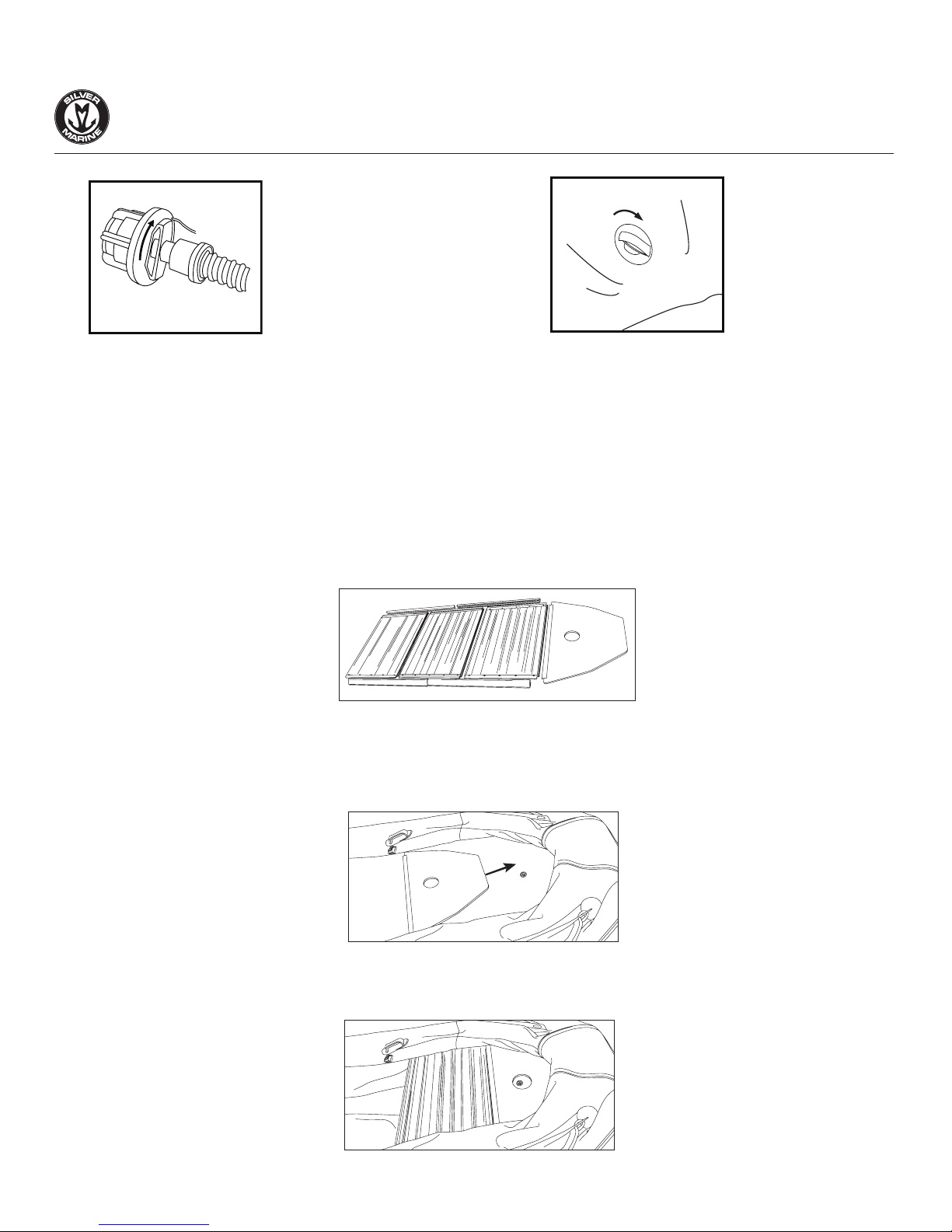
1. Slide in Wooden board-1
Start by fitting the bow wooden board between air tubes and bottom. Slide and push it forward as for as
possible, until it has reached the tip of the bow, and that the air valve of the inflatable keel fits into the
hole in the bow wooden board.
2. Install AL board-2
Simply slide AL board-2 against wooden board-1 with modest pressure. Make sure the edge of board-2
fits into the rear end of board-1.
3
4
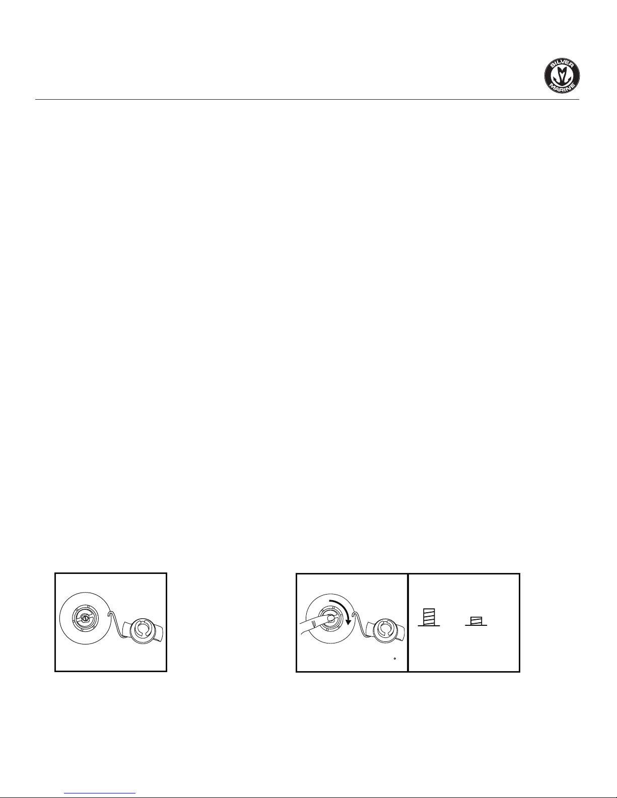
3. Insert the inflation adapter to the valve. Secure
the adapter by turning it clockwise. Connect the
pressure gauge and pump to the adapter. Start
inflating until the pressure reach 0.25 bar.
4. Remove the pressure gauge and pump. Put
the cap on the valve.
6
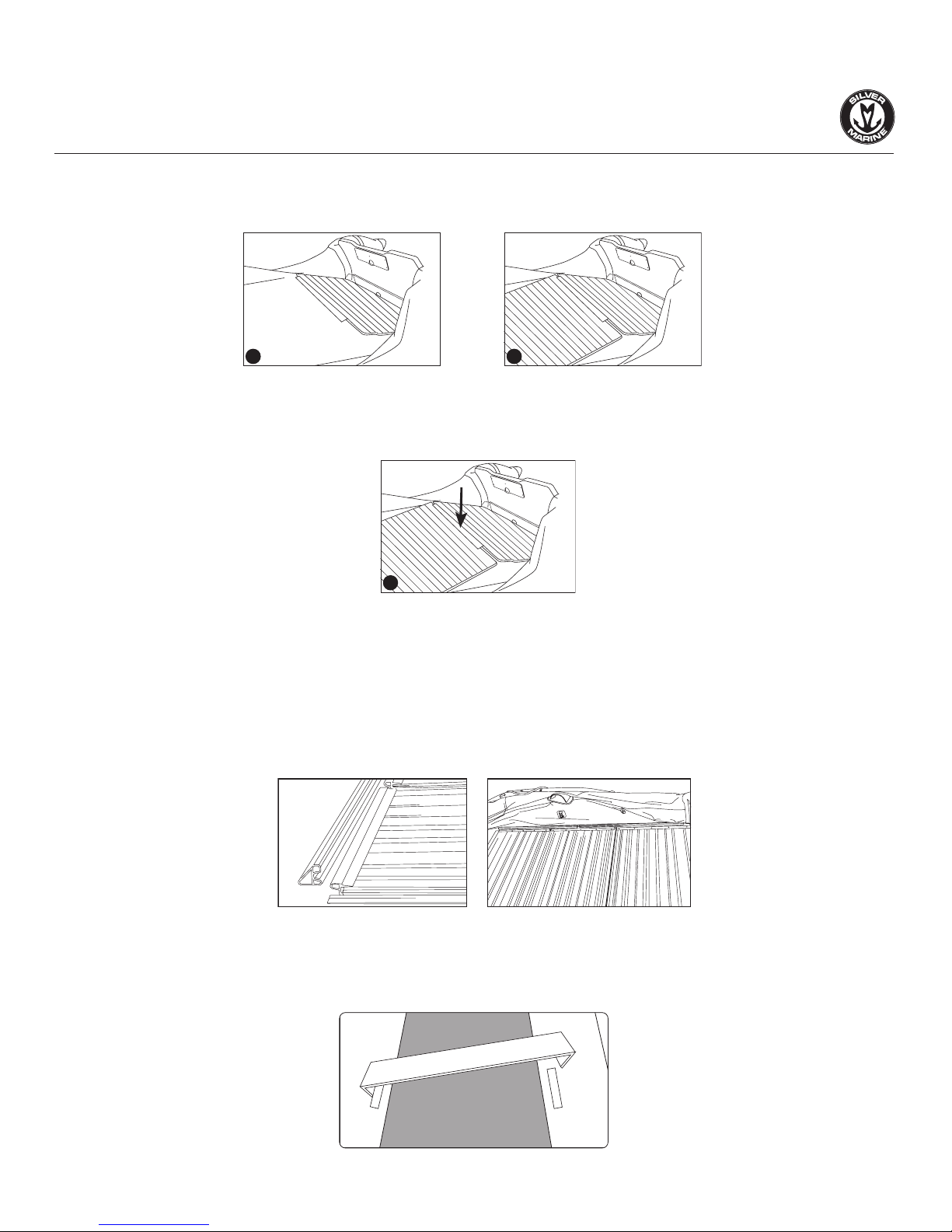
3. Install AL board-3, 4
Install the aluminium floor boards by following the picture instructions below
4. Side Stringers Assembly
There are 4 sturdy aluminium side stringers that hold the floor boards in one piece and keep the boards
steady.
Put one stringer on to fit the angle between each board and the buoyancy chambers. Complete the
second stringer assembly by repeating the process.
NOTE: Do not rest the completed boards on the inflated hull material.
5. Install Seating Board
When the air deck is in position, hook the plastic brackets at the bottom of the plywood bench into the
PVC straps on your Silver Marine® boat.
Start by fitting the back board to the
rear end. Lift the other side a little to
make space for the last board.
Connect the last board to the back of
board 1, lift the other side and connect
to the rear board’s lifted side.
Push down the 2 boards at the joint
part.
21
3
7
6. Seat bag assembly
After the Seat Assembly, attach the bench seat bag onto the bench seat.
7. Install front storage bag.
STEP THREE: FINISH INFLATION
After inflating the tubes, insert the barometer against the valve. Check if the pressure in the air cham-
bers reaches 0.25 bars, then remove the barometer and screw the cap on.
STEP FOUR: OAR ASSEMBLY
Press down the button on one end of the oar and then insert another blade end. Then fully fit the oar into
the fixed holders on both sides of buoyancy tubes.
STEP FIVE: SELF-BAILING DRAIN VALVE
Push the plug into sleeve located in the transom.
Note: Always make sure the plug is secured into the valve before launching the boat and do not open
while afloat.
8

MOTOR IN STALLATION
Most outboard motors can be mounted directly onto the transom engine mounting plate. Read the
instruction manual supplied by separate outboard motor manufacturer. All outboards are slightly different,
and some require special installation procedures. Below is a general outline:
1. Set the motor on tilt and tilt the mounting bracket.
2. Place the motor in the center of the transom.
3. Screw the mounting brackets securely to the transom.
WARNING
1. Read the entire manual before mounting or operating the outboard motor.
2. Gasoline (Petrol) is highly flammable, and its vapors are flammable and explosive. Handle and store
gasoline (petrol) carefully. Make sure there are no gas fumes or leaking fuel before starting the engine.
3. Improper mounting of the outboard motor could result in hazards such as poor handling, loss of
control, or fire.
4. If any item in the pre-operation check is not working properly, have it inspected and repaired before
operating the outboard motor. Otherwise, accidents may occur.
DEFLATION AND DISASSEMBLY
You only need to turn the Joint Screw Gasket counterclockwise for easy deflation.
IMPORTANT: Do not deflate one chamber completely while keeping others fully inflated. This could
damage the bulkheads of your boat.
PRESERVATION
You should endeavour to keep your Silver Marine® in good condition. Preferably store it deflated. If you
leave it outside, raise it up off the ground and cover it from the elements especially strong sunshine, or
heavy, cold, raining, conditions. If you leave it in the water, use a boat cover. If you store it in a closet,
basement or garage, we suggest you pick a cool and dry spot. Keep the boat clean and dry.
Every boat now includes a boat cover to keep it protected while not in use.
Take the cover
out of packaging.
Identify the front
side of the cover.
(with Silver Marine
logo).
Assemble the boat cover front first,
then the back.
After assembly,
tighten clasp at
back.
Finish
THE PROCESS TO ASSEMBLE A BOAT COVER
9

MAINTENANCE
1. Inflate the boat to working pressure. At this time you do not need to install the removable boards,
seat, oars and outboard engine.
If wet, leave the boat to dry, but avoid leaving it directly in the sun. Any quality problem occuring from
long time in the sun without using it is not a product problem, and will not be covered by the warranty.
3. When dry, vacuum it in order to get any sand, gravel, rubbish or debris off the bottom, pay extra
attention to the inflatable keel and in the gaps between the floor and tube.
4. Clean the boat all over with ordinary soap and water and rinse thoroughly with fresh water.
5. Check the inflation valves, clean them and remove any sand or debris.
REPAIRING
Your Silver Marine® boat comes with a repair kit for patching minor punctures. Through use you may
occasionally puncture your boat. Most leaks only take a few minutes to repair.
Leakage of Air: If your boat appears a bit sift, it might not be because of a leak, since any change in
temperature can cause modifications 0.003 bar (0.045 psi) per Celsius degree (34F). If the boat was
inflated late in the day, that air might cool overnight. The cooler air exerts less pressure on the hull, so
it could appear soft the next morning. If there has been no temperature variation, you need to first
determine exactly where the air is leaking. Please follow these instructions:
1. Check that there is no sand or debris within the air valve.
2. Make sure that the valve gasket is in place.
3. Inflate the buoyancy chamber.
4. Close the cap on all the valves.
5. Rinse the boat with soapy water, including perimeter of the inflation valves.
6. Wherever bubbles appear, that is the location of the leak to be repaired.
Small Repairs: Deflate your boat. Thoroughly clean (you can use vinyl cleaner for this purpose) and dry
the area to be repaired. For a small puncture (less than 1/8 inch) apply a small drop of glue. Let dry 12
hours.
If the bubbles appeared around the inflation valves, the valves maybe loose. The valves are a nut and bolt
system: with the tube deflated, hold the back of the valve through the fabric and use moderate strength
to tighten the front.
If no bubbles appeared either on the fabric or around the valve when the buoyancy chamber was inflated,
cover the CLOSED cap of the valve with soapy water. If bubble appears then the valve must be changed.
With the tube deflated, unscrew the front of the valve and replace it with a new one.
If the leak is located in the buoyancy chamber, please follow the below instructions:
Small Repairs: Deflate your boat. Thoroughly clean (you can use vinyl cleaner for this purpose) and dry
the area to be repaired. For a small puncture (less than 1/8 inch) apply a small drop of glue. Let dry 12
hours.
10
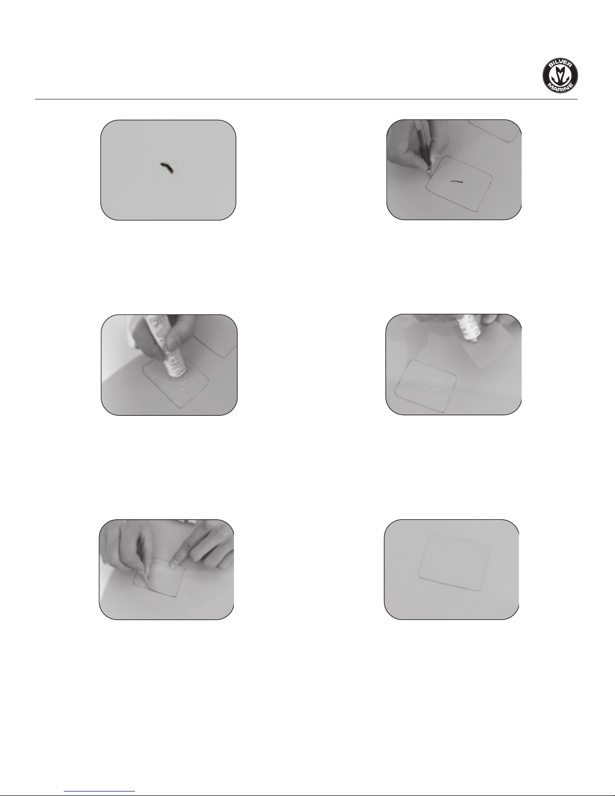
2. Cut a piece of repair material large enough to
overlap the damaged area by approximately 1/2
inch. Use a pencil to trace the outline of the patch.
1. Thoroughly clean the area surrounding the leak
to remove any dirt or grime.
3. Apply adhesive to the underneath side of patch and around the area to be repaired. Coat the affected
area lightly but completely with glue. Let the glue sit for 2-4 minutes until it appears tacky.
4. Place the patch on the damaged area and press down firmly. Allow 12 hours for repair to dry. After
patch has dried, apply glue around the edges for a complete seal (dry for 4 hours).
11

OPERATION ON YOUR SILVER MARINE®
Rowing
Silver Marine® transom boats can be rowed easily.
Motoring & Safety
Silver Marine® transom boats are responsive and quick under power, and turn and track very well. All
boats have their maximum horsepower range, so take time to familiarize yourself with how your Silver
Marine® maneuvers in various conditions.
Basic seamanship is beyond the scope of this owner’s manual, but we would like to go over a few
fundamentals. It is your responsibility to be aware of and comply with all relevant safety regulations. In
all water sports you should have reasonable swimming ability. Always respect the water and weather,
both can change rapidly and have surprised even the most seasoned mariner. Always carry enough
approved personal floatation devices (Life jackets) for every passenger. We strongly suggest that all
boaters enroll in at least one of the excellent water safety courses.
Towing
Tie each end of a small line to the front side D-Rings on your boat to form a bridle. Tie your
towline to this bridle, and not to the carry handle in the front of the boat. Using the bridle
will distribute the force of towing across the hull.
Stability and buoyancy
a) Stability is reduced by any weight added high up;
b) Air tanks shall not be punctured;
c) Breaking waves are a serious stability hazard.
FOLDING & STORAGE
1. Lie your inflatable boat on a clean flat surface, then deflate the buoyancy chambers.
2. Remove oars or paddles and removable rowing seat.
3. Fold the aft cones towards the transom.
4. Fold the buoyancy compartments inwards, i.e. towards the center of the boat.
5. Close the caps over the valves in order to avoid any damage to the hull material.
6. Fold the boat around the transom from the back.
7. Fold the bow section on top of the previously folded rear part of the boat.
Place the boat inside your Silver Marine® carry bag or protective covering. When storing your inflatable
boat, ensure protection against rodents and other vermin, as they feed on the fabric of the boat.
12

PROBLEM POSSIBLE REASONS POSSIBLE SOLUTION(S)
Buoyancy chamber
looses air
Rise or drop of temperature
Inflatable keel is not sufficiently inflated
Buoyancy collar is not sufficiently inflated
Aluminium stringers are not adequately
installed
Engine is incorrectly mounted
Load is not distributed correctly
Hull is full of water
Oar has been installed incorrectly
Plastic valve cap has not been fitted
Loose valve
Puncture
Aluminium board
not rigid enough
Boat does not get
on plane
Oar slips out of the base
MAINTENANCE
MAINTENANCE
MAINTENANCE
REPAIRING
ALUMINIUM BOARDS, SEAT AND
SEAT BAG ASSEMBLY
MOTOR INSTALLATION
MOTOR INSTALLATION
SELF-BAILING DRAIN VALVE
STEP FOUR: OARS ASSEMBLY
STARTING UP
STARTING UP
TROUBLESHOOTING CHART
Warning:
1. Please read the owner’s manual carefully before using.
2. Please retain owner’s manual for future reference.
3. Follow the instructions in the Owner’s Manual, including the data given on the capacity
plate. Uneven distribution of people or loads in the boat could result in danger.
4. Please refrain from using the boat at winds above 6-level and waves above 2 m.
5. Please pay attention to suspicious liquid such as leaking oil. It may lead to danger.
6. Always beware of offshore winds and currents.
7. Not for use in whitewater/ rapids.
8. Not a life saving device.
9. Not for use by children without adult supervision.
“WARNING – Do not exceed the maximum recommended number of persons.
Regardless of the number of persons on board, the total weight of persons and equipment
must never exceed the maximum recommended load. Always use the seats/seating spaces
provided.
“WARNING – When loading the craft, never exceed the maximum recommended load.
Always load the craft carefully and distribute loads appropriately to maintain design trim
(approximately level). Avoid placing heavy weights high up.”
D
S
U
13

SOMMAIRE
INTRODUCTION GÉNÉRALE AU MANUEL DU PROPRIÉTAIRE................................................16
TERMINOLOGIE DE STRUCTURE...........................................................................................17
CARACTÉRISTIQUES TECHNIQUES.......................................................................................17
TERMINOLOGIE DE BATEAU................................................................................................18
LISTE D’EMBALLAGE...........................................................................................................19
POINTS D’INSTALLATION.....................................................................................................19
ETAPE UNE: POUR COMMENCER......................................................................................19
ÉTAPE DEUX : ASSEMBLÉE DE PLANCHE ET DE SIÈGE...................................................20
ÉTAPE TROIS: INFLATION DE FINITION............................................................................22
ÉTAPE QUATRE : INSTALLATION ET ASSEMBLÉE D’AVIRONS..........................................22
ÉTAPE CINQ : VALVE DE VIDANGE PAR SOI-MÊME...........................................................22
INSTALLATION DE MOTEUR.................................................................................................23
DÉFLATION ET DÉMONTAGE................................................................................................23
CONSERVATION..................................................................................................................23
ENTRETIEN...........................................................................................................................24
RÉPARATION........................................................................................................................24
PLIAGE ET STOCKAGE.........................................................................................................26
OPÉRATION SUR VOTRE SILVER MARINE®.........................................................................26
CANOTAGE.....................................................................................................................26
CIRCULATION ET SÛRETÉ..............................................................................................26
REMORQUAGE.................................................................................................................26
STABILITÉ ET FLOTTABILITÉ...........................................................................................26
DIAGRAMME DE DÉPANNAGE.............................................................................................27
15
FRENCH

INTRODUCTION GÉNÉRALE AU MANUEL DU PROPRIÉTAIRE
Ce manuel a été conçu pour vous aider à vous servir de votre bateau avec une plus grande sécurité
et meilleur plaisir. Il contient tous les détails techniques et d’usage du bateau, ainsi que
l’équipement qu’il inclut. Le lire soigneusement et cela vous permettra de vous familiariser avec
avant de l’employer.
Ce manuel de propriétaire ne contient des informations que d’ordre général quant à l’utilisation d’un
bateau. Si c’est votre première utilisation, ou si vous venez de changer pour une embarcation qui ne
vous est pas très familière, pour votre propre sûreté, assurez-vous d’obtenir l’information nécessaire
quant à la manipulation du navire ainsi que des essais si vous le pouvez. Votre concessionnaire
nautique ou club de voile homologué par la fédération seront heureux de vous conseiller vers des
« bateaux- école », ou vers des instructeurs compétents.
Merci de bien vouloir vous assurer des bonnes conditions météorologiques avant d’effectuer une
sortie en bateau et que vous et votre équipage soient capables d’utiliser et de répondre à tout
éventuel problème à bord.
Même si votre bateau est certifié designs de catégorie A, B ou C, (de la tempête très dure et très
violente en catégorie A aux conditions difficiles pour la catégorie C) il existe des conditions dans
lesquelles, seul un équipage averti peut partir en mer.
Ce manuel n’est pas un guide d’entretien vraiment détaillé. Si vous rencontrez par hasard des
difficultés dont vous ne trouvez pas la réponse dans ce manuel, merci de bien vouloir contacter les
personnes compétentes pouvant vous aider à ce sujet. Le fabricant n’est aucunement responsable
pour des modifications ayant été faites sur le produit qu’il n’a pas approuvé.
Dans certains pays, un permis de conduire ou une autorisation est nécessaire pour naviguer, ou des
règlements spécifiques sont en vigueur. Bien entretenir sont bateaux et anticiper toutes
détériorations qui pourraient advenir dans le future.
N’importe quel bateau, peu importe sa robustesse, peut être sévèrement endommagé s’il n est pas
utilisé correctement. Toujours ajustez la vitesse et la direction du bateau en mer.
Toutes les personnes devraient porter une aide appropriée de flottabilité (gilet de sauvetage/
dispositif personnel de flottaison) quand il est a bord. Notez que, dans quelques pays, le port du
gilet est obligatoire.
VEUILLEZ MAINTENIR CE MANUEL DANS UN ENDROIT SUR, LE REMETTRE AU NOUVEAU
PROPRIETAIRE SI VOUS ETES AMENEZ A LE VENDRE.
Merci d’avoir choisi les bateaux pneumatiques Silver Marine®. Ils sont soigneusement fabriqués à la
main avec un tissu de 1100 Decitex. Tissu enduit de PVC des deux côtés et ils sont aussi
composés d’un tableau de bord et de différents sols. Ce manuel a été conçu afin que vous puissiez
conserver votre bateau plus longtemps et en profiter plus longuement. Merci de bien vouloir le lire
avec attention et de vous familiariser avec.
Ce bateau s’accorde directement avec les exigences de la directive Européenne 94/25/EC en
accord avec le design de catégorie C.
Conçu pour de paysages côtiers, pour les baies, les estuaires, les lacs et les rivières et pour des
conditions de vents jusqu’ à force 6 et des hauteurs de vagues jusqu’à 2m.
16
TERMINOLOGIE DE STRUCTURE
1. Arc
2. Panneau libre
3. Quille
4. Poupe
5. Ligne de flottaison
6.Avance
7. Arri
8. Faisceau
9. Traverse
10. Longueur totale
11. Côté droit
12. Bâbord
4
1
25
3
CARACTÉRISTIQUES TECHNIQUES
MODELE
NO. DE NORME
CATEGORE DE CONCEPTION
DIMENSIONS
(coque gonflé, longueur x poutre)
PUISSANCE DE MOTEUR MAX
CAPACITE DE PASSAGERE MAX
CHARGE UTILE MAX
PRESSION DE TRAVAIL RECOMMANDEE
POIDS
Calypso 360 AL
C. TYPE V
EN ISO6185-2:2001
11’9” x 5’9”
(3.59 x 1.76m)
20HP (14.7kw)
5 +1
1191lbs (540kg)
0.25 barre*
141lbs (64kg)
Calypso 420 AL
C, TYPE V
EN ISO6185-3:2001
14’ x 6’3”
(4.26 x 1.91m)
30HP (22.5kw)
7
1653lbs (750kg)
0.25 barre*
195lbs (89kg)
II
* La pression d’utilisation conçue pour chaque chambre de flottabilité est 0.25 barre tandis qu’elle est également
recommandée par le fournisseur de ne pas être moins de 0.18 barre.
12 11
6
10
7
8
9
17

5. AVIRONS
5. AVIRONS
2.COUSSIN DE
2.COUSSIN DE
BANQUETTE
BANQUETTE
1.ANNEAU D'ATTELAGE EN D
1.ANNEAU D'ATTELAGE EN D
3.SAISINES DE
3.SAISINES DE
SÉCURITÉ
SÉCURITÉ
4.
4.
LISTON DE FROTTAGE
LISTON DE FROTTAGE
6.SOUPAPE DE VIDANGE
6.SOUPAPE DE VIDANGE
7.TRAVERSE PRETE AU MOTEUR
7.TRAVERSE PRETE AU MOTEUR
9.VALVES ENCASTRÉES
9.VALVES ENCASTRÉES
10.PVC DE HAUTE QUALITÉ
10.PVC DE HAUTE QUALITÉ
POUR L'EAU DE MER
POUR L'EAU DE MER
8.ALUMINIUM DECK
8.ALUMINIUM DECK
5. AVIRONS
2.COUSSIN DE
BANQUETTE
1.ANNEAU D'ATTELAGE EN D
3.SAISINES DE
SÉCURITÉ
4.LISTON DE FROTTAGE
6.SOUPAPE DE VIDANGE
7.TRAVERSE PRETE AU MOTEUR
9.VALVES ENCASTRÉES
10.PVC DE HAUTE QUALITÉ
POUR L'EAU DE MER
8.ALUMINIUM DECK
TERMINOLOGIE DE BATEAU
18
LISTE D’EMBALLAGE.
1). Boîte Calypso 360 AL:
La coque de bateau, avirons, pompe de pied, baromètre, siège en bois, la corde d’amarrage, la ligne de
sécurité, 4 valves de vis + 1 soupape de vidange, Sac de rangement sur le banc, Sac de rangement avant,
Taud de mouillage, le kit de réparation et sac portable.
1 morceaux de planches, 4 morceaux de la lisse.
2). Boîte Calypso 420 AL:
La coque de bateau, avirons, pompe de pied, baromètre, siège en bois, la corde d’amarrage, la ligne de
sécurité, 5 valves de vis + 1 soupape de vidange, Sac de rangement sur le banc, Sac de rangement avant,
Taud de mouillage, le kit de réparation et sac portable.
1 morceaux de planches, 4 morceaux de la lisse.
POINTS D’INSTALLATION
POINT 1 : Bien que le bateau soit conçu pour se monter individuellement, une personne additionnelle peut
faciliter le montage.
POINT 2 : Veiller à bien enfoncer les tiges en aluminium dans les planches de bois, dans la longueur.
POINT 3 : Veiller à enfoncer et tourner le commutateur instantané de ressort 90 degrés avant le gonflage. (Le
réglage de défaut est dégonflement.)
POINT 4 : En cas du pompe électrique, après l’gonflage de tube, utiliser une pompe de pied d’ajouter peu plus
d’air pour assurer assez de pression.
POINT 5 : Au cas où la valve est lâche, visser-le fortement avec la clé en plastique noire, qui est incluse dans
les accessoires.
Point 6: Si vous l’installation du banc sur le bateau vous est difficile, exercer une légère pression avec vos
genoux sur le tube ou vous fixez la deuxième attache. La pression sera moins forte et vous aurez donc plus de
facilité pour mettre en place le banc.
ETAPE UNE: POUR COMMENCER
1. Dévoiler la coque.
Dégager un espace plat (s’assurer qu’il est propre et exempt d’objets pointus). Enlever la coque de la boîte et
enlever le sac en plastique. Dérouler la coque et le mettre à plat.
2. installation de valve de vis
1
2.2
HAUT BAS
(A) GONFLER (B) DEGONFLER
2.1
APPUYER ET TOURNER
A 90
o
DEGRES
1. TEnlever le chapeau de la valve. (La
valve par défaut est à la position de
déflation).
2. Presser le commutateur de ressort et tourner dans le sens
d’une montre par 90 degrés assurez vous que le commutateur
est sauté vers le haut.
Notes : Pour dégonfler, appuyer sur le bouton intérieur au
centre et tourner 90 degrés dans le sens contraire des aigu-
illes de montre.
19
This manual suits for next models
1
Table of contents
Languages:
Other Silver Marine Boat manuals


