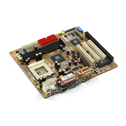
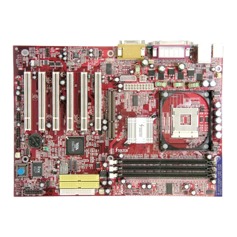
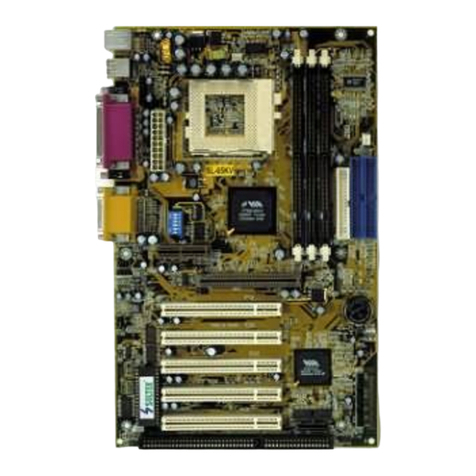
SOLTEK 65kv User manual

65KV
1
This User‘s Guide & Technical Reference is for assisting system
manufacturers and end-users in setting up and installing the
mainboard.
Every effort has been made to ensure that the information in this
manual is accurate. Soltek Computer Inc. is not responsible for
printing or clerical errors. Information in this document is subject to
change without notice and does not represent a commitment on
the part of Soltek Computer Inc.
No part of this manual may be reproduced, transmitted, translated
into any language in any form or by any means, electronic or
mechanical, including photocopying and recording, for any purpose
without the express written permission of Soltek Computer Inc.
Companies and products mentioned in this manual are for identifi-
cation purpose only. Product names appearing in this manual may
or may not be registered trademarks or copyrights of their respec-
tive companies.
Soltek computer inc. Provides this manual “As is “ without war
ranty of any kind, either express or implied, including but not
limited to the implied warranties or conditions of merchantability or
fitness for a particular purpose. In no event shall Soltek computer
inc. Be liable for any loss or profits, loss of business, loss of use or
data, interruption of business, or for indirect, special, incidental, or
consequential damages of any kind, even if Soltek computer inc.
Has been advised of the possibility of such damages arising from
any defect or error in this manual or product.
© Copyright 2000 Soltek Computer Inc.
All rights reserved.
http://www.soltek.com.tw
e-mail: [email protected]
EDITION : March 2000
VERSION : V2.0
65KV
2
C O N T E N T
Chapter 1: Introduction ............................... 4
1-1 CPU .................................................................................... 4
1-2 CHIPSET ............................................................................ 4
1-3 L2 CACHE .......................................................................... 4
1-4 MAIN MEMORY .................................................................. 4
1-5 BIOS ................................................................................... 5
1-6 MULTI-I/O FUNCTION........................................................ 5
1-7 AC97 CODEC FUNCTION ................................................. 5
1-8 MISCELLANOUS ............................................................... 5
1-9 MAINBOARD LAYOUT....................................................... 7
1-10 MAINBOARD CHIPSETS DIAGRAM ............................... 8
1-11 SYSTEM MEMORY CONFIGUATION .............................. 8
Chapter 2: Hardware Setup......................... 9
2-1 CPU TYPE CONFIGURATION ........................................... 9
2-2 JUMP SETTINGS............................................................. 12
2-3 CONNECTORS ................................................................ 17
2-4 DRIVER INSTALLATION.................................................. 18
Chapter 3: BIOS Setup .............................. 20
3-1: INTRODUCE THE BIOS. ................................................ 20
3-2: WHAT IS SETUP............................................................. 20

65KV
3
3-3: HOW TO RUN SETUP .................................................... 21
3-4: WHAT IS THE CMOS...................................................... 21
3-5: WHAT IS POST............................................................... 21
3-6 CMOS SETUP UTILITY ................................................... 22
3-7 STANDARD CMOS SETUP ............................................. 23
3-8 BIOS FEATURES SETUP................................................ 25
3-9 CHIPSET FEATURES SETUP ......................................... 29
3-10 POWER MANAGEMENT SETUP .................................. 33
3-11 PnP / PCI CONFIGURATION SETUP ............................ 36
3-12 LOAD SETUP DEFAULTS ............................................. 38
3-13 CPU SPEED SETTING .................................................. 39
3-14 INTEGRATED PERIPHERALS ...................................... 40
3-15 SUPERVISOR / USER PASSWORD ............................. 43
3-16 IDE HDD AUTO DETECTION ........................................ 44
3-17 SAVE & EXIT SETUP .................................................... 44
3-18 EXIT WITHOUT SAVING................................................ 44

65KV
4
Chapter 1: Introduction
1-1 CPU
• Supports Intel®PPGA Celeron™ 370 CPUs at 233MHz ~ 700MHz.
• Supports Intel®FC-PGA Pentium !!!®Coppermine CPUs using at 500E
~ 750 MHz or higher.
• Supports Cyrix Joshua PR400/ PR450/ PR500 CPUs.
• Supports CPU voltage Auto-Detect circuit.
1-2 CHIPSET
• VIA 694X chipset (North Bridge) and VIA 686A chipset (South Bridge).
• Supports two 32-bit 3.3V/5V system bus. (one is AGP and the other is
PCI)
• Supports 66/100/133MHz CPU external bus speed.
• AGP 3.3V 1x/2x mode, AGP 1.5V 4x mode and PCI 2.1 compliant.
• Concurrent CPU and AGP access.
• Pipelined transfers up to 533MB/sec.
• Windows 95 OSR2 VxD and integrated Windows 98 / Windows 2000
miniport driver support.
• Ultra ATA33/66 Master Mode PCI EIDE controller.
• USB (Universal Serial Bus) connector.
• Sophisticated PC98-compatible Mobile Power Management.
1-3 L2 CACHE
• Intel®Celeron™ CPU supports 128K write back cache with Pipelined
Burst SDRAMs.
• Intel®Pentium !!!®Coppermine supports 256K/ 512K write back cache
with Pipelined Burst SDRAMs.
1-4 MAIN MEMORY
• Supports total memory from 8MB to 768MB (SDRAM).
• Supports 3pcs 168pin DIMM sockets. ( 3.3V Unbuffered and 4 Clock
type)
• Supports SDRAM with 12ns/10ns/8ns speed.

65KV
5
1-5 BIOS
• Award BIOS.
• Supports Plug & Play (PnP).
• FLASH MEMORY for easy upgrade.
• Supports Advanced Power Management (APM) Rev 1.2 function.
• Supports Advanced Configuration Power Management Interface (ACPI)
Rev 1.0 function.
• Year 2000 compliant.
1-6 MULTI-I/O FUNCTION
• One floppy port supports up to 2.88MB.
• 2x Built-in USB connectors.
• Ultra ATA33/66 bus master IDE supports up to 4 IDE devices. (Including
ZIP / LS-120 floppy devices)
• 2x 16550A Built-in fast UART compatible serial port connectors.
• Built-in SPP / EPP / ECP parallel port connectors.
• Built-in standard IrDA TX / RX header.
• Peripherals boot function with ATX power.
1-7 AC’97 CODEC FUNCTION
• SoundBlast Pro Hardware and Direct Sound Ready AC’97 Digital Audio
Controller.
1-8 MISCELLANOUS
• ATX form factor.
• Mainboard size: 18mm X 30.5mm.
• Provides 5x PCI slots, 1x ISA slot, 1x AMR slot, 1x AGP slot and 3x
DIMM sockets.
• AGP 2.0 interface with 1x 2x / 4x data transfer and 2x / 4x fast write
capability.
• AGP Universal Connector supports via dual mode buffers.
• Supports SCSI, CD-ROM, ZIP, LS-120 boot up function.
• Supports Wake On LAN (WOL) boot up function.
• Supports BIOS Writing Protection.
• Supports BIOS Core Voltage Setting. (Optional)
• Provides DIP switch for easy setting.

65KV
6
NOTE: To use Wake On LAN (WOL) function, the ATX
power supply must provide at least 5V/720mA
standby current capacity.

65KV
7
1-9 MAINBOARD LAYOUT
• Mainboard default setting: Celeron 300A/66MHz.
NOTE: Under 100MHz / 133MHz FSB, the SDRAM spec must complaint PC-100 / PC-133 spec.
1 3
1 3
JP6
JP7
3
1
3
1
JP8
JP9
1 3
1 3
1 3
1 4
1 4 JP3
JP4 JP5
1 3 JP12
1
3
JP11
1 3 JP10
1
3
JP2
3
1
JBAT1
SPK RST PWR/LED SUSLED
HD/LED IR PWR SUSPEND
FAN2
FAN1
J2 J3
1 1
LPT1
CO 2 CO 1
GA E/ IDI PORT
LINE
OUT
LINE
IN
IC
JWOL1
SW1
CD_IN2
CD_IN1
A R
AGP
ISA
PCI 1
PCI 2
PCI 3
PCI 4
PCI 5
DI 1
DI 2
DI 3
FDC1
IDE2
IDE1
SOCKET 370
RT2
RT1
ATX POWER
FLASH BIOS
Li
Battery
ON DIP
1 2 3 4 5 6
USB2
2 16
1 15
AC'97
Codec
Clock
Generator
PS/2
OUSE
PS/2
K/B
upper
lower
USB1
USB0
upper
lower
VIA
694X
VIA
686A

65KV
8
1-10 MAINBOARD CHIPSETS DIAGRAM
3D
Graphics
Controller
SDRAM,
EDO,
or FPG
Clock
Buffer
Clock
Generator
Slot-1 or Socket-370
Host CPU
VT82C694X
Pro 133A
North Bridge
510 BGA
VT82C686A
Mobile South
324 BGA
AGP Bus
GCLK
GCKRUN#
PCI Bus
SMIACT#
CKE#
Memory Bus
SMI# / STPCLK# / SLP#
PCLK
HCLK
CPUSTP#
PCKRUN#
Power Plane & Peripheral ControlUSB GPIO and ACPI EventsKeyboard / Mouse
ATA 33/66
BIOS ROM
ISA PCISTP#
SMBus
MCLK
SUSCLK,
SUSST1#
PCLK
HCLK
Apollo Pro 133A system with VT82C686A Mobile South-Bridge
1-11 SYSTEM MEMORY CONFIGURATION
This VIA 693Apollo Pro-Plus motherboard supports 168 pin DIMM of
4MB, 8MB, 16MB, 32MB or 64MB or 128MB to form a memory
size between 8MB to 768MB (SDRAM). VIA 693 Apollo Pro-Plus
chipsets provide “ Table Free ” function. It means that users can install
DRAM with any configuration and in any bank, and that is why the
DRAM table is not needed but do remember that the DRAM must be 3.
3V type.

65KV
9
Chapter 2: Hardware Setup
2-1 CPU TYPE CONFIGURATION
OFF
OFF
OFF
ON
ON
ON
ON
1 2 3 4 5 6
Celeron 333/66
Pentium III 500E/100*
Pentium III 667B/133* 5.0x
OFF
OFF
OFF
OFF
ON
ON
ON
1 2 3 4 5 6
Celeron 366/66
Pentium III 550E/100*
Pentium III 733B/133* 5.5x
OFF
OFF
ON
ON
ON
ON
ON
1 2 3 4 5 6
Celeron 400/66
Pentium III 600E/100* 6.0x
OFF
OFF
OFF
ON
ON
ON
ON
1 2 3 4 5 6
Celeron 433/66
Pentium III 650/100* 6.5x
OFF
OFF
OFF
ON
ON
ON
ON
1 2 3 4 5 6
Celeron 466/66
Pentium III 700/100* 7.0x
OFF
OFF
OFF
OFF
ON
ON
ON
1 2 3 4 5 6
Celeron 500/66
Pentium III 750/100* 7.5x
OFF
OFF
OFF
ON
ON
ON
ON
1 2 3 4 5 6
Celeron 533/66 8.0x
OFF
OFF
OFF
ON
ON
ON
ON
1 2 3 4 5 6
Celeron 233/66 3.5x
OFF
OFF
ON
ON
ON
ON
ON
1 2 3 4 5 6
Celeron 266/66
Pentium III 533EB/133* 4.0x
OFF
OFF
OFF
ON
ON
ON
ON
1 2 3 4 5 6
Celeron 300/66
Pentium III 600EB/133* 4.5x
CPU MODEL SW1 CPU RATIO
* : Pentium III Coppermin FC-PGA CPUs.

65KV
10
3.0x
3.5x
4.0x
4.5x
5.0x
5.5x
14
ON
ON
ON
ON
OFF
14
ON
ON
ON OFF
OFF
14
ON
ON
ON
ON
OFF
14
ON
ON
ON OFF
OFF
14
ON
ON
ON
OFF
OFF
14
ON
ON
OFF
OFF
OFF
6.0x
6.5x
7.0x
7.5x
8.0x
14
ON
ON
ON
ON OFF
14
ON
ON
ON
OFF
OFF
14
ON
ON
ON OFF
OFF
14
ON
ON
OFF
OFF
OFF
14
ON
ON
ON OFF
OFF
SW1 DIP1 ~ DIP4: BUS RATIO SELECT
SW1 DIP5 ~ DIP6: BUS CLOCK SELECT
ON
OFF
ON
1 2 3 4 5 6
66/100/133 Hz
Auto Select
(default)
ON
OFF
ON
1 2 3 4 5 6
ON
OFF
OFF
1 2 3 4 5 6
100 Hz
133 Hz
SW1 DIP5 ~ DIP6 JP2: FSB Select
1
3
1
3
1
3

65KV
11
WATCH OUT !!!
1. Please refer to your processor installation or other
documentation attached with your CPU for detailed
installing instruction.
2. Installing a heat sink and cooling fan is necessary
for proper heat dissipation from your CPU. Uncor-
rected installation may result in overheating and
damage of your CPU.
3. Before changing the setting of CPU Vcore from
BIOS program, user SHOULD make sure of correct
specification both of CPU CLOCK and RATIO.
Uncorrected setting may cause damage to your
CPU.

65KV
12
FAN# FUNCTION
FAN1 CPU FAN
FAN2 SYSTEM FAN
FAN#: Onboard FAN (12V) Connector.
2-2 JUMP SETTINGS
JP3 / JP4: USB Port Select (1)
USB Port Select JP3 / JP4
Redirect USB port3 to
USB2 connector (default) 1 3
1 3
JP3
JP4
Redirect USB port3 to
AMR 1 3
1 3
JP3
JP4
USB Port Select JP6 / JP7
Redirect USB port2 to
USB2 connector (default) 1 3
1 3
JP6
JP7
Redirect USB port2 to
AGP 1 3
1 3
JP6
JP7
JP6 / JP7: USB Port Select (2)
JP5 / JP9: AC’97 Codec Control
AC’97 Codec JP5 / JP9
Disabled 3
1
1 3
JP5 JP9
Enabled (default) 3
1
1 3
JP5 JP9

65KV
13
JP8: Power Lost Resume
This feature must work with BIOS. Please refer to the BIOS “Power On
After PWR-Fail” sector.
Power Lost Resume JP8
3
1
Enabled
3
1
Normal (default)
JBAT1: Clear CMOS Data
Before you clear the CMOS data, it’s necessary to turn the power off first
(including +5V standby power). Otherwise, the system may work
abnormally or malfunction.
CMOS Status JBAT1
3
1
Retain Data (default)
3
1
Clear CMOS Data
JP10 / JP11 / JP12: Intel / Cyrix CPU Select
CPU TYPE
Intel CPU (default)
Cyrix JOSHUA CPU
JP10
1 3
1 3
JP12
1 3
1 3
JP11
1
3
1
3

65KV
14
CD1/CD2: CD-ROM Audio Connector
GAME/MIDI Port:
Connect joystick or MIDI to this connector.
MIC :Microphone Jack
Connect to microphone device.
LINE IN: Audio In Jack
Connect audio line in.
LINE OUT/SPEAKER OUT: Audio Out Jack
Connect audio line out or speaker out.
JWOL1: Wake On LAN (WOL) Connector
This connector is designed to boot up system via LAN. Connect the wake
on signal form the LAN card to this connector.
RT2: Thermal Sensor Connector
a: Connect to RT2.
b: Connect this thermal sensor to
particular device which generates
lots of heat such as Hard Disk,
VGA chip, etc. When connected,
user could observe the tempera-
ture change from the BIOS
program.
Left Channel
PIN 1 Left Channel
CD_IN1PIN # CD_IN2
GND
PIN 2 GND
GND
Right Channel
PIN 3 GND
PIN 4 Right Channel

65KV
15
PIN1~PIN4: HDD DISK LED CONNECTOR
Connect cable from the chassis’s “H.D.D” to this connector.
PIN6~PIN10: IR (INFRARED) CONNECTOR
Connect cable from the chassis’s “IR” to this connector.
PIN12~PIN13: ATX POWER SWITCH CONNECTOR
Connect cable from the chassis’s “POWER” to this connector.
J2 SIGNAL DESCRIPTIONPIN
HDD LED CONNECTOR
+5V
1
HDD LED SIGNAL
2
HDD LED SIGNAL
3
+5V
4
NONE
5
N.C.
NONE
11
N.C.
N.C.
ATX POWER SWITCH ATX POWER SWITCH
12
GND
13
N.C.
14
N.C.
15
INFRARED CONNECTOR
INFRARED TRANS IT SIGNAL
6
GND
7
INFRARED TRANS IT SIGNAL (LOW SPEED)
8
NONE
9
+5V
10

65KV
16
J3 SIGNAL DESCRIPTIONPIN
SPEAKER CONNECTOR
SPEAKER SIGNAL
1
NO CONNECTION
2
GND
3
+5V
4
GND
15
SUSPEND LED
NONE
7
N.C.
N.C.
RESET SWITCH
NONE
11
NONE
12
RESET SIGNAL
5
GND
6
POWER LED CONNECTOR
+5V
8
NO CONNECTION
9
GND
10
NONE
13
SUSPEND LED
14
PIN1~PIN4: SPEAKER CONNECTOR
Connect cable from the chassis’s “SPEAKER” to this connector.
PIN5~PIN6: RESET SWITCH
Connect cable from the chassis’s “RESET” to this connector. User can
use this function to make a hardware re-boot. Press and hold this switch
at least one second to re-boot.
PIN8~PIN10: POWER LED CONNECTOR
Connect to Power LED.
PIN14~PIN15: SUSPEND LED CONNECTOR
Connect to Suspend LED.

65KV
17
2-3 CONNECTORS
J2, J3:
A. : PS/2 MOUSE
C. : LPT1 PORT
E. : PS/2 KEYBOARD
G. : COM1
I. : LINE/SPK OUT
K. : MIC
B. : USB 0
D. : GAME/MIDI PORT
F. : USB 1
H. : COM2
J. : LINE IN
A.
E. F. G. H. I. J. K.
B. C. D.
1
1
15
15
EF G
C
H I
D
A1 A2 B
J2
J3
++
--
+-
A1: 1st HDD LED
B. : INFRARED (IR)
D. : NONE
F. : RESET SWITCH
H. : NONE
A2: 2nd HDD LED
C. : POWER SWITCH
E. : SPEAKER
G. : POWER LED
I. : SUSPEND LED

65KV
18
2-4 DRIVER INSTALLATION
Onboard AC’97 Audio Codec Controller Driver Installation for Win-
dows95 / Windows98:
1. Go to CD-ROM driver, we suggest the CD-ROM title is D:\.
2. Find and run D:\DRIVER\AUDIO\VIA AC97\SETUP.EXE
3. Then the setup program will detect your O.S. to install relative files
into your system.
4. Reboot your computer.
NOTE 1: IF USER WANTS TO USE EXTERNAL SOUND CARD, USER
MUST RUN BIOS PROGRAM TO DISABLE “Onchip Sound”
option in the “Chipset Feature Setup” and “Onboard
Legacy Audio” option in the “Integrated Peripherals”.
NOTE 2: UNDER WINDOWS95, USER MUST INSTALL Direct X FOR
AGP ENVIRONMENT.
NOTE 3: User can also install 4in1 Driver from CD instead of the
following drivers. (For avoid CD-ROM compalibility issue,
user can ignore the IDE driver)
1. Put the CD into your CD-ROM.
2. There appears a welcome window.
(If doesn’t, it means that your CD-ROM auto-run function does not
enable, but you still can browser the CD via Windows Explorer and
change the directory to where your CD-ROM directory is. Then run the
autorun.exe)
3. Select “Install Driver”.
4. Select “Install VIA Chipsets Driver”.
5. Select “Install 4in1 Driver”.
6. Then the program will automatically setup all drivers your
system needs.
7. Finally, the system will re-boot.
NOTE: AFTER INSTALLED “ 4in1 Driver”, USER DOESN’T
NEED TO INSTALL ANY OTHER PROGRAM IN PART 2.
PART 1:

65KV
19
VIA Patch Code Installation
Windows95 / Windows98:
1. Go to CD-ROM driver, we suggest the CD-ROM title is D:\.
2. Find and run D:\Patch\Via\patch9x\Setup\Setup.exe
3. Select “Install VIA Chipset Functions’ Registry”, then it will automati-
cally install this program.
NOTE: This program should be installed before any other VIA’s
drivers.
VIA AGP VxD Driver for Windows9x Installation
Windows95 / Windows98:
1. Go to CD-ROM driver, we suggest the CD-ROM title is D:\.
2. Find and run D:\Driver\Via\Agp\Setup\Setup.exe
3. Select “Install VIA AGP VxD in turbo mode” or “Install VIA AGP VxD
normal mode”, then it will automatically install this program.
VIA PCI IRQ Routing Miniport for Windows9x Installation
Windows95 / Windows98:
1. Go to CD-ROM driver, we suggest the CD-ROM title is D:\.
2. Find and run D:\Patch\Via\Virq9x\Setup.exe
NOTE: Before install Windows98, user must enable two functions
for this miniport driver in the BIOS menu, one is “OnChip
USB” in the “Chipset Features Setup” and another is “Assign
IRQ for USB” in the “PnP/PCI Configuration Setup”.
PART 2:

65KV
20
Chapter 3: BIOS Setup
3-1: INTRODUCE THE BIOS.
BIOS stands for Basic Input Output System. It is sometimes call the
ROM BIOS because it is stored in a Read-Only Memory (ROM)
chip on the motherboard. BISO is the first program to run when you
turn on your computer. It performs the followin functions:
• initializing and testing hardware in your computer (a process called
“POST”, for Power On Self Test)
• loading and running your operating system.
• managing SETUP for making changes in your computer.
• helping your operating system and application programs to manage
your PC hardware by means of a set of routiness called BIOS Run-
Time Services.
3-2: WHAT IS SETUP
SETUP is an interactive BIOS program that you need to run when:
• Changing the hardware on your system. (for example: installing a new
Hard Disk, etc.)
• Modifying the behavior of your computer. (for example: changing the
system time or date, or turning special features on or off, etc.)
• Enhancing your computer’s behavior. (for example: speeding up
performance by turning on shadowing or caching.)
Table of contents
Other SOLTEK Motherboard manuals

SOLTEK
SOLTEK SL-75LIV User manual

SOLTEK
SOLTEK B7A-F User manual

SOLTEK
SOLTEK 85DIR User manual

SOLTEK
SOLTEK SL-67EB Plus User manual

SOLTEK
SOLTEK SL-PM800I-R User manual

SOLTEK
SOLTEK 865Pro-FGR User manual

SOLTEK
SOLTEK 85DRV4-C User manual

SOLTEK
SOLTEK SL-65ME-T User manual

SOLTEK
SOLTEK 75FRV User manual

SOLTEK
SOLTEK K8AV2-R User manual

SOLTEK
SOLTEK SL-K8T-939FL User manual

SOLTEK
SOLTEK SL-67B-W User manual

SOLTEK
SOLTEK SL-56H5 User manual

SOLTEK
SOLTEK KT400-C User manual

SOLTEK
SOLTEK SL-85DR User manual

SOLTEK
SOLTEK SL-85DRV+ User manual

SOLTEK
SOLTEK SL-B8E-FG User manual

SOLTEK
SOLTEK SL-75DRV3/75DRV3+ User manual

SOLTEK
SOLTEK SL-75DRV-X User manual

SOLTEK
SOLTEK SL-65EP+-T User manual