FIC PA-2013 User manual

PA-2013
MOTHERBOARD
MANUAL
DOC No. : 16449
Rev. : A0
Date : 5, 1998
Part No. : 25-10864-
20

Handling Precautions
Warning :
1. Static electricity may cause damage to the integrated circuits on the
motherboard.
Before handling any motherboard outside of its protective packaging,
ensure that there is no static electric charge in your body.
2. There is a danger of explosion if the battery is incorrectly replaced.
Replace only with the same or an equivalent type recommended by the
manufacturer.
3. Discard used batteries according to the manufacturer’s instructions.
Observe the following basic precautions when handling the motherboard or
other computer components:
nWear a static wrist strap which fits around your wrist and is connected to a
natural earth ground.
nTouch a grounded or anti-static surface or a metal fixture such as a water
pipe.
nAvoid contacting the components on add-on cards, boards and modules
with the “gold finger” connectors plugged into the expansion slot. It is best
to handle system components by their mounting bracket.
The above methods prevent static build-up and cause it to be discharged
properly.
Trademark
All trademarks mentioned in this manual are registered properly of the
respective owners.
Copyright
This manual may not, in whole or in part, be photocopied, reproduced,
transcribed, translated, or transmitted in whatsoever form without the written
consent of the manufacturer, except for copies retained by the purchaser for
personal archival purposes.
Notice

i
Chapter 1 Overview
Package Checklist.................................................................................. 1
The PA-2013 Motherboard............................................................ 2
Main Features........................................................................................ 3
Intelligent Properities............................................................................. 5
Chapter 2 Installation Procedures
1). Set System Jumpers .......................................................................... 7
Jumpers ........................................................................................ 7
Motherboard Layout...................................................................... 8
Clear Password: CPS............................................................. 10
Flash ROM Type Selection: EP1, EP2 ................................... 10
CPU to SRAM Data Transacting Mode Selection: SRAM ...... 11
2). Install System RAM Modules............................................................ 11
RAM Module Configuration.......................................................... 11
Install and Remove DIMMs........................................................... 12
DIMM Frequency: CLK4, SDRAM............................................... 13
System Frequency: NBCLK1, NBCLK2 ........................................ 13
Cache Memory.............................................................................. 14
3). Install the CPU ................................................................................. 15
CPU External (BUS) Frequency: CLK1, CLK2, CLK3 .................. 16
CPU to Bus Frequency Ratio: FREQ1, FREQ2, FREQ3................. 16
Set CPU Frequency:...................................................................... 17
Set CPU Voltage........................................................................... 18
4). Install Expansion Cards .................................................................... 19
5). Connect Devices ............................................................................... 20
Connect to Internal Devices........................................................... 20
Floppy Diskette Drive Connector: FLOPPY ........................... 20
IDE HDD Device Connectors: PRIMARY, SECONDARY..... 20
ATX Power Connector: POWER............................................ 20
CPU Fan Connector: FAN1.................................................... 21
Wake-On-LAN (WOL) Connector: RWU............................... 21
Connect to System Case ................................................................ 22
Front Panel Block Connector: F_PNL .................................... 22
System Case Fan Connector: FAN2........................................ 24
Chassis Open Alarm Connector: CHASSIS1 .......................... 24
Connect to External Devices.......................................................... 25
Table of Contents

PA-2013 Motherboard Manual
ii
PS/2 Keyboard and Mouse Connector: KB, MS...................... 25
Universal Serial Bus Connectors: USB0, USB1, F_USB........ 25
Printer Connector: LPT.......................................................... 26
Serial Port Connectors: COM1, COM2 .................................. 26
Infrared Connector: IR ........................................................... 26
Chapter 3 BIOS Setup
CMOS Setup Utility............................................................................... 27
Standard CMOS Setup........................................................................... 28
Hard Disk Configurations.............................................................. 28
Software Turbo Speed................................................................... 29
BIOS Features Setup.............................................................................. 29
Chipset Features Setup........................................................................... 32
Power Management Setup...................................................................... 35
PNP/PCI Configuration .......................................................................... 39
Load BIOS Defaults............................................................................... 41
Load Setup Defaults............................................................................... 41
Integrated Peripherals ............................................................................ 42
Supervisor/User Password...................................................................... 46
IDE HDD Auto Detection....................................................................... 46
Save and Exit Setup............................................................................... 47
Exit without Saving................................................................................ 47
Chapter 4 Software Utilities
Starting Installation................................................................................ 49
LANDesk Client Manager...................................................................... 49
Three Options of LDCM Setup...................................................... 49
Desktop Management Interface (DMI).................................................... 51
Starting DMI................................................................................. 51
Editing DMI.................................................................................. 51
Adding DMI.................................................................................. 52
Loading DMI ................................................................................ 52
Saving DMI .................................................................................. 53
Bus Master IDE Driver .......................................................................... 54
Installation.................................................................................... 54
Patch for Chipset.................................................................................... 55
Installation.................................................................................... 55

Installation Procedures
iii
AGP VxD Support Utility ...................................................................... 56
System Requirements.................................................................... 56
Installation.................................................................................... 56
BIOS Flash Software.............................................................................. 57
Downloading BIOS File ................................................................ 57
Upgrading BIOS File..................................................................... 57
Loading New BIOS Defaults ......................................................... 57
Anti-Virus Tool...................................................................................... 58
Hardware Requirements................................................................ 58
Technical Notes ............................................................................ 58

PA-2013 Motherboard Manual
iv
This Page Intentionally Left Blank

1
Overview
Based on the new highly-integrated VIA APOLLO MVP3 Chipset that offers
100MHz system bus operations and accepts 100MHz PC100 synchronous
DRAMs, the PA-2013 combines blistering Pentiumprocessor performance
with support for switching voltage regulator which allows the voltage from
2.0V to 3.5V,intelligent diagnostic, and power management features. The new
Accelerated Graphics Port (AGP) interface provides a dedicated path for
memory-intensive graphics applications-delivering faster system performance
and arcade-quality 2x mode 3D graphics. The PA-2013 has a versatile ATX-
size platform for leading-edge PC ’97 compliant systems. For the most up-to-
date information and the latest FAQs and BIOS updates, visit FIC Online at
http://www.fic.com.tw/.
Package Checklist
Please check that your package contains all the items listed below. If you
discover any item is damaged or missing, please contact your vendor.
nThe PA-2013 motherboard
nThis user manual
nOne IDE device cable
nOne floppy disk drive cable
nSoftware Utilities
Chapter 1

PA-2013 Motherboard Manual
2
The PA-2013 Motherboard

Overview
3
Main Features
nEasy Installation
||BIOS with support for Plug and Play, auto detection of IDE hard drives,
||LS-120|drives, IDE ZIP drives, MS Windows 95/ 98/NT, and OS/2.
nLeading Edge Chipset
VIA APOLLO MVP3 chipset with integrated DRAM and LII cache
controllers as well as support for Intel's new Dynamic Power Management
Architecture (DPMA), Concurrent PCI (PCI 2.0 and 2.1), AGP 1.0
compliant, and USB.
nFlexible Processor Support
Onboard 321-pin ZIF socket and switching voltage regulator support
complete range of leading-edge processors:
Intel Pentium P54C 100/133/166/200MHz processors.
Intel Pentium MMX 166/200/233MHz processors.
|||||||||AMD-K6-166 / K6-200 / K6-233 / K6-266 / K6-300, also K6-2/266 and ||||
|||||||||K6-2/300 processors.
|||||||||Cyrix 6x86MX-PR166 / PR200 / PR233 / PR266 processors.
|||||||||Cyrix 6x86L-PR200+ / PR166+ / PR150+ processors.
|| ||| |IBM 6x86MX-PR166 / PR200 / PR233 / PR266 processors.
|||||||||IBM 6x86L-PR200+ / PR166+ / PR150+ processors.
|
nVarious External Bus and CPU/Bus Frequency Ratio Support
The motherboard supports the Bus frequency of 66 / 75 / 83 / 100MHz and
the CPU/Bus frequency ratio of 1.5x / 2x / 2.5x / 3x / 3.5x / 4x / 4.5 x / 5x /
5.5x by a switching voltage regulator which accepts from 2.0V to
3.5V.|||(Please read Install the CPU in Chapter 2 for more information).
nUltra-fast Level II Cache
Supports 512KB/1MB onboard Pipeline Burst Level II write-back cache.
nVersatile Main Memory Support
Accepts up to 768MB DRAM in three banks by using of 8, 16, 32, 64,
128, ||256MB with support for EDO and SDRAM (66/100MHz) DIMMs.
nISA and PCI Expansion Slots
Two 16-bit ISA Bus and four 32-bit PCI Bus expansion slots provide the
room to install a full range of add-on cards.

PA-2013 Motherboard Manual
4
nOnboard Accelerated Graphics Port (AGP)
One 32-bit AGP slot supports 1x/2x AGP VGA cards for superior 3D video
and graphics performance with transfer speeds up to 264MB/second under
1x transfer mode and up to 528MB/second under 2x transfer mode.
nEnhanced PCI Bus Master IDE Controller with Ultra DMA/33 Support
Integrated Enhanced PCI Bus Master IDE controller features two dual-
channel connectors that accept up to four Enhanced IDE devices, including
CD-ROM and Tape Backup Drives, as well as Hard Disk Drives
supporting the new Ultra DMA/33 protocol which doubles data transfer
rates to 33MB/sec. Standard PIO Mode 3, PIO Mode 4, and DMA Mode 2
devices are also supported.
nSuper Multi I/O
Integrated Winbond 83877TF Plug and Play multi-I/O chipset features two
high-speed UART 16550 compatible serial ports, one EPP/ECP capable
parallel port, and one FDD connector.
nUSB Support
Two USB ports integrated in the rear I/O panel allow convenient and high-
speed Plug and Play connections to the growing number of USB compliant
peripheral devices on the market. One manufacturing optional USB
connector that shared with one USB port for the front panel.
nOnboard IrDA Connector
An IrDA connector for wireless infrared connections is available.
nRemote Wake On LAN Support
Onboard RWU connector allows remote management on your network
even the system is power off. This feature provides a simpler and
convenient control to LAN-based networks.
nIntel LANDesk Client Manager (LDCM) Software Support (optional)
LDCM is a DMI-compliant application for local and network management
of desktop client systems. The application reduces the number of help desk
calls by supplying the user with self diagnostics such as a PC health meter
and local alert of potential problems.

Overview
5
Intelligent Properties
nOptimized MMX Performance
The motherboard utilizes the advanced features of the VIA APOLLO
MVP3 chipset to optimize the unrivaled performance of the Intel
Pentiumprocessor with MMX technology. To provide you with
additional flexibility, the motherboard also supports other leading-edge
processors featuring MMX technology, including the AMD-K6, Cyrix
6X86MX, IBM 6x86MX processors.
nOnboard Accelerated Graphics Port (AGP)
The motherboard is installed one 32-bit AGP bus with a dedicated
66MHz/133MHz path from the graphics card to the system memory (in 2x
mode) offering much greater bandwidth than the 32-bit PCI bus does
which currently operates at a speed of 33MHz. The board is fully
compliant with the AGP 1.0 specification. AGP enabled 3D graphics cards
can directly access main memory across this fast path instead of using local
memory. To make use of the improved AGP performance, the motherboard
should be installed with SDRAM type memory and the VGA card and
drivers should also be fully AGP compliant. Using Microsoft’s Windows
98 and Windows NT 5.0 which implement DirectDraw will allow the
system to take full use of AGP’s benefits without the need to install
additional drivers.
nCPU Thermal Monitoring Alert
An onboard sensor LM75 monitors the CPU temperature to make sure that
the system is operating at a safe heat level. If the temperature is too high,
the sensor automatically generates an SMI (System Management Interrupt)
to slow down the CPU clock frequency. At the same time, the system warns
you that the CPU is overheating if the LDCM is on. CPU utilization is
restored to normal levels when the temperature returns to a safe level. This
feature requires a power supply with a soft-off power controller. Please also
read the feature of CPU Warning Temperature of BIOS Setup for related
information.
nLightning-Fast SDRAM Performance
The motherboard supports general 66MHz and the new generation of
lightning-fast 100MHz SDRAM via its onboard 168-pin DIMM sockets.
SDRAM delivers an added boost to overall system performance by
increasing the CPU-to-memory data transfer rate. SDRAM performance on

PA-2013 Motherboard Manual
6
the PA-2013 is further boosted by the board’s integrated I2C controller,
which optimizes the memory timing settings.

Overview
7
This Page Internationally Left Blank
7
Installation Procedures
The motherboard has several user-adjustable jumpers on the board that allow
you to configure your system to suit your requirements. To set up your
computer, you should follow these installation steps: 1). set system jumpers; 2).
install RAM modules; 3). install the CPU; 4). install expansion cards; 5).
connect devices; 6). set up BIOS feature. 7). set up supporting software tools.
CAUTION: If you use an electric drill to install this motherboard on your
chassis, please wear a static wrist strap. The recommended electric drill
torque is from 5.0 to 8.0 kg/cm to avoid damaging the chips’ pins.
1). Set System Jumpers
Jumpers
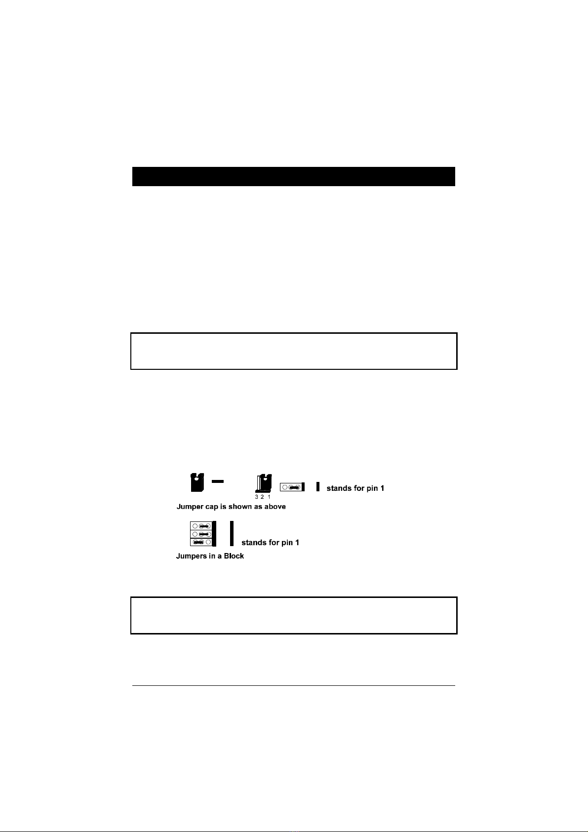
Jumpers are used to select the operation modes for your system. To set a
jumper, a black cap containing metal contacts is placed over the jumper pins
according to the required configuration. A jumper is said to be shorted when
the black cap has been placed on one or two of its pins. The types of jumpers
used in this manual are shown below:
NOTE: Users are not encouraged to change the jumper settings not listed in
this manual. Changing the jumper settings improperly may adversely affect
system performance.
Chapter 2
PA-2013 Motherboard Manual
8
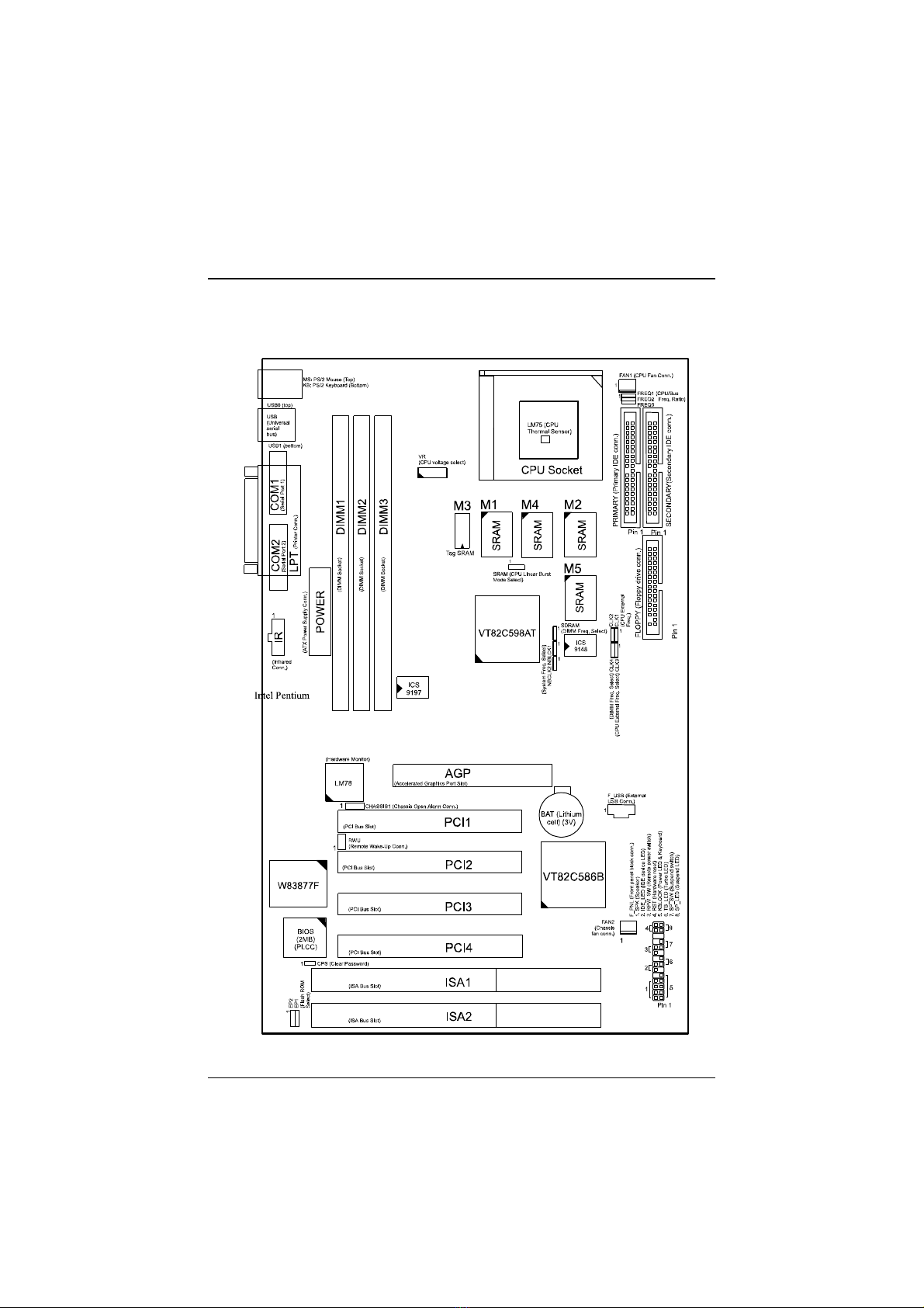
Motherboard Layout

Installation Procedures
9
Onboard Mark Meaning Page
CPS Clear Password 10
EP1, 2 Flash ROM Type Selection 10
SRAM CPU to SRAM Data Transacting Mode
Selection 11
CLK4, SDRAM DIMM Frequency Selection 13
NBCLK1,NBCLK2 System Frequency Selection 13
CLK1, 2, 3 CPU External (Bus) Frequency Selection 16
FREQ1, 2, 3 CPU to Bus Frequency Ratio Selection 16
VR CPU Voltage Selection 18
DIMM1, 2, 3 Memory Module Socket 11
CPU ZIF Socket 7 ZIF Socket7 for Processor 15
AGP Accelerated Graphic Port Slot 19
PCI1, 2, 3, 4 PCI Bus Expansion Slot (32-bit) 19
ISA1, 2 ISA Bus Expansion Slot (16-bit) 19
FLOPPY Floppy Diskette Drive Connector 20
PRIMARY,
SECONDRAY IDE Device Connector 20
POWER ATX Power Connector 20
FAN1 CPU Fan Connector 21
RWU Wake-On-LAN Connector 21
F_PNL* Connectors for LEDs & Switches on Front Panel 22
FAN2 System Case Fan Connector 24
CHASSIS1 Chassis Open Alarm Connector 24
KB PS/2 Keyboard Connector 25
MS PS/2 Mouse Connector 25
LPT Parallel Port 25
USB0, USB1, F_USB Universal Serial Bus Connector 25
COM1, COM2 Serial Port 26
IR Infrared Connector 26
* includes PWR_LED, KB_LOCK, TB_LED, SP_SW, SPK, SP_LED, IDE_LED,
RPW_SW, and RST connectors.
PA-2013 Motherboard Manual
10
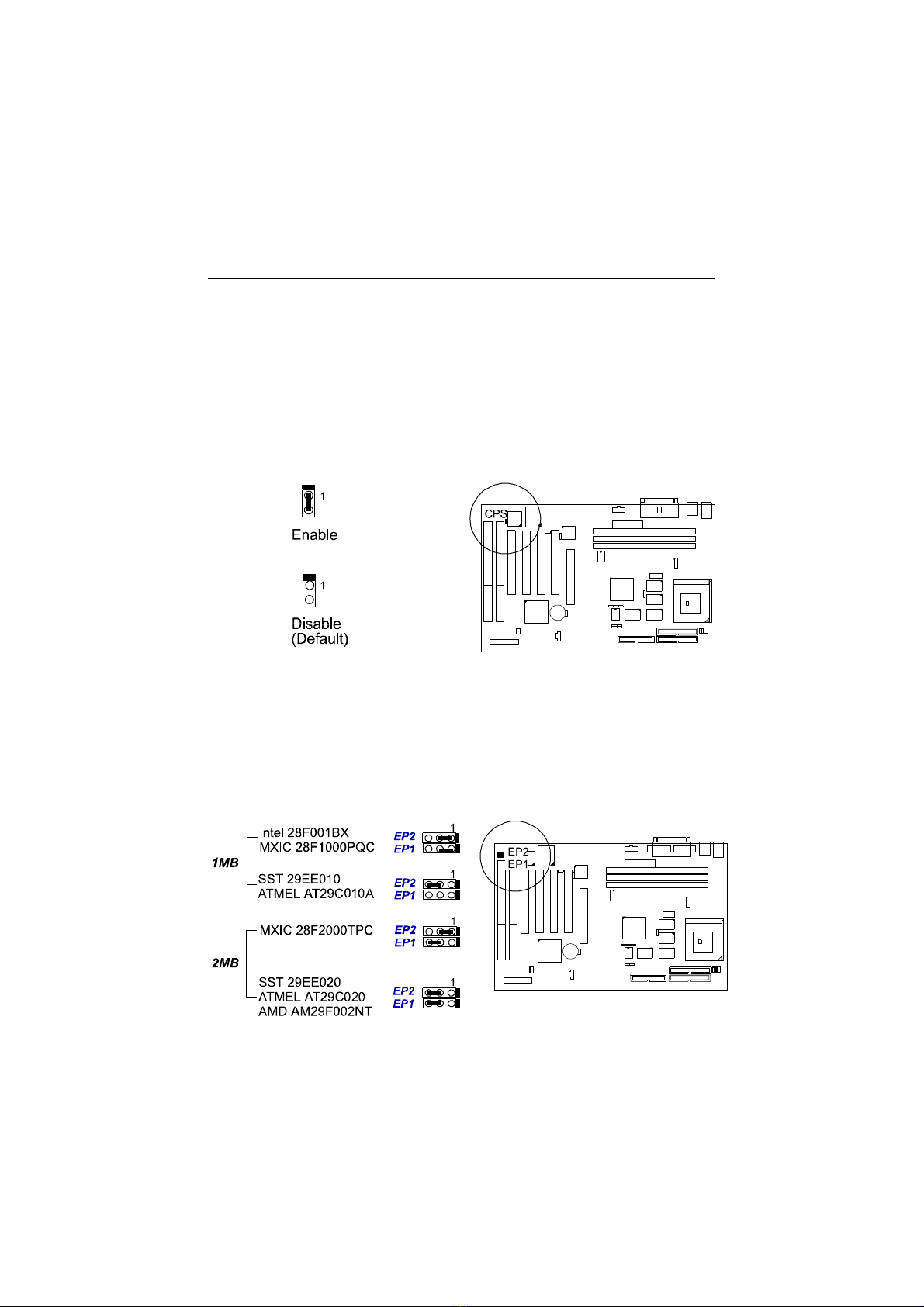
Clear Password: CPS
This jumper allows you to enable or to disable the password configuration. You
may need to enable this jumper by shorting it with a jumper cap if you forget
your password. To clear the password setting: 1. Turn off your computer, (2).
Short this jumper by placing a jumper cap on it, (3) Turn on your computer,
(4), Hold down the Delete key during bootup and enter BIOS Setup to re-enter
user preferences, (5) Turn off your computer, (6) Remove the jumper cap, (7)
Turn on your computer for the new settings to take effect.
Flash ROM Type Selection: EP1, EP2
These two jumpers allow you to configure the type of flash ROM chip. This
jumper setting is correct by manufactory default. If you want to know the flash
ROM type installed on this motherboard, remove the sticker from the chip to
see its type.

Installation Procedures
11
CPU to SRAM Data Transacting Mode Selection: SRAM
This jumper allows you to select the CPU to SRAM data read/write mode.
If you install a Cyrix or IBM processor on this motherboard, please set at 2-3
pin pair. Please also read Linear Burst feature of BIOS Setup, Chapter 3 for
more information.
2). Install System RAM Modules
RAM Module Configuration
This motherboard provides three onboard DIMM sockets for allowing 3.3V
(unbuffered) EDO/SDRAM DIMM modules. Either 8, 16, 32, 64, 128MB, or
256*MB DIMM can be installed on these three sockets. The maximum total
memory supported is up to 768MB*.
NOTE:
1. * A RAM module of this size was not available for testing at time of
printing.
2. This board only supports 3.3V (unbuffered) EDO/SDRAM modules.
3. ||This motherboard supports DIMMs with data access time of 15ns, |||||||
|||||||12ns, 10ns, 8ns or less. ECC memory and parity check is also
|||||||supported. Please also refer to the feature of Memory ECC Check of
|||||||Chapter 3 for more information.
4. |If DIMM runs at the speed of 100MHz, it must meet the PC100
|||||||Specification.

PA-2013 Motherboard Manual
12
Install and Remove DIMMs
This motherboard supports 100MHz SDRAM DIMMs; that is, the system
frequency of this motherboard runs in a higher speed rather than the speed of
66MHz.
Complete the following procedures to install DIMMs:
1. Locate the DIMM slots on the motherboard. (See figure below.)
2. Install the DIMM straight down into the DIMM slot with both hands.
3. The clips of the slot will close up to hold the DIMM in place when the
DIMM touches the slot’s bottom.
Press the clips with both hands to remove the DIMM.
Installation Procedures
13
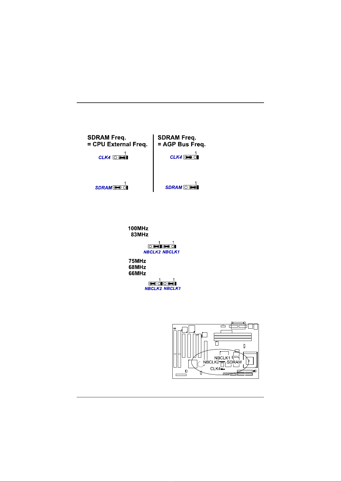
DIMM Frequency: CLK4, SDRAM
System Frequency: NBCLK1, NBCLK2
Other manuals for PA-2013
1
Table of contents
Other FIC Motherboard manuals


