Simco-Ion 6432e User manual

IONIZATION SOLUTIONS
Point of Use
Ionizing Blower
Model 6432e
User’s Manual

19-6432-M-01 Rev 4
About Simco-Ion
Simco-Ion develops, manufactures, and markets system solutions
to manage electrostatic charge. As the world's largest provider of
electrostatics management products and services, Simco-Ion
improves its customers' business results by providing a total
solution to their electrostatic discharge and electromagnetic
interference challenges. Simco-Ion Technology Group is a division
of Illinois Tool Works (ITW), located in Alameda, California. For
more information about Simco-Ion visit www.simco-ion.com or call
800-367-2452. Simco-Ion is ISO 9001 and ANSI ESD S20.20
certified.
© 2013 Simco-Ion

19-6432-M-01 Rev 4
Contents
1 Description .......................................................................... 1
1.1 Point of Use Ionizing Blower Model 6432e .............................................. 2
1.2 IsoStat® Technology................................................................................ 4
1.3 Performance ............................................................................................ 5
1.4 Power Requirements ............................................................................... 6
2 Set Up & Operation ............................................................. 7
2.1 Box Contents ........................................................................................... 8
2.2 Mounting Stand Installation and Placement........................................... 10
2.3 Mounting Stand Knob Replacement ..................................................... 13
2.4 Blower Placement.................................................................................. 14
2.5 Power Connections............................................................................... 15
2.6 FMS Connection ................................................................................... 18
2.7 Turning on the Blower........................................................................... 19
2.8 Alarms................................................................................................... 20
3 Maintenance ...................................................................... 21
3.1 Maintenance Requirements.................................................................. 22
3.2 Cleaning the Chassis............................................................................ 23
3.3 Cleaning the Emitter Points .................................................................. 24
4 Specifications.................................................................... 25
5 Warranty & Service .......................................................... 31

19-6432-M-01 Rev 4 1
1
Description
1.1 Point of Use Ionizing Blower Model 6432e
1.2 IsoStat® Technology
1.3 Performance
1.4 Power Requirements
19-6432-M-01 Rev 4 2
1.1 Point of Use Ionizing Blower Model
6432e
The Point of Use Ionizing Blower Model 6432e controls static
discharge in areas where static build-up can cause contamination,
ESD, material-handling problems, or microprocessor lock-up. The
internal emitter points are electrostatically shielded to eliminate
field-induced charging. Steady-state DC ion emission provides fast
discharge with low airflow.
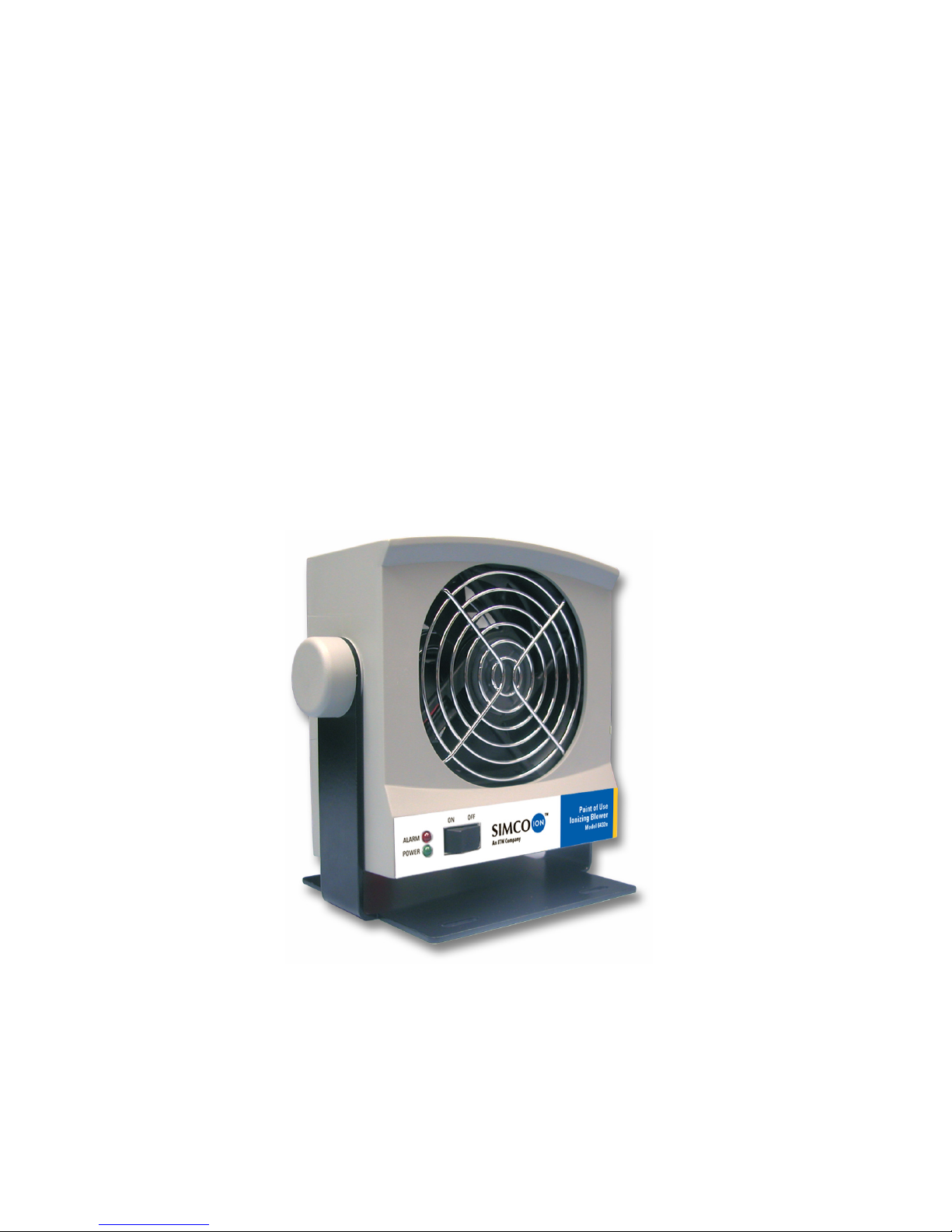
The Model 6432e features a red alarm indicator LED on the front of
the Blower. See 2.8 Alarms section for a discussion of the alarm
function. The eight-pin terminal strip provides a 4-20 mA current
loop and relay output connection to your facility monitoring system
(FMS) in addition to the 24 VDC input connection.
Figure 1. Front of the Model 6432e Blower

19-6432-M-01 Rev 4 3
Figure 2. Back of Model 6432e Blower

19-6432-M-01 Rev 4 4
1.2 IsoStat®Technology
IsoStat technology makes Simco-Ion ionizing Blowers the most
reliable ionizers available. IsoStat enables them to operate without
grounding wires or cables and still maintain ionizer balance. The
Model 6432e Blower’s internal emitter points are electrostatically
shielded to eliminate field-induced charging. Steady-state DC ion
emission provides fast discharge with low airflow.
Ionizers incorporating IsoStat technology never need calibration
and require very little maintenance. IsoStat is based on a law of
physics, Conservation of Charge, which states that charge cannot
be created or destroyed in an isolated system. By isolating the
ionizer’s emitter points from ground, IsoStat ensures equal numbers
of positive and negative ions.

19-6432-M-01 Rev 4 5
1.3 Performance
The Blower will reduce a static charge of ±1,000V down to ±100V in
approximately 4 seconds at a distance of 1 ft. (30.48 cm) when
powered with 24 VAC. See the table below for typical discharge
times as determined by distance. Distance is measured from the
front center of the Blower. Ionization balance is better than ±20V at
1 ft. (30.48 cm).
Table 1. Distance/Discharge Time when Powered with 24 VAC
Testing was performed with a charged plate monitor in accordance
with ionization standard ANSI/ESD STM3.1-2006 of the ESD
Association.
Distance Discharge Time
1 foot (30.48 cm) 4 seconds
2 feet (61 cm) 7 seconds
3 feet (91.44 cm) 11 seconds
4 feet (122 cm) 17 seconds
Note: The performance of the Model 6432 will be reduced slightly
when the unit is powered with 24 VDC.

19-6432-M-01 Rev 4 6
1.4 Power Requirements
The Model 6432e Blower can receive power from four different
sources. Three different power supplies are available as options for
the Blower, providing 24 VDC or 24 VAC. The fourth power source
for the Blower is 24 VDC from your process equipment using the
terminal block and eight pin connector on the rear of the Blower.
The maximum power requirement for the Blower is 6W.
Simco-Ion offers three power supplies for use with this product:
• Transformer (part number 14-1320-01) for use with 120 VAC/60
Hz systems.
• Transformer (part number 14-1330) for use with 230 VAC/50 Hz
systems.
Both 14-1320-01 and 14-1330 provide the Blower with appropriate
24 VAC power.
• Universal power supply (part number 14-1322) for use with
100-240 VAC systems provides 24 VDC output.
Caution:
The use of improper input voltage may result in poor
performance or damage to the unit. The transformer should
not be operated beyond the specified electrical limit as
described in the Specifications section of this manual.
Damage caused to the transformer from operation in an
environment that exceeds the specified limits will void the
warranty.
Achtung:
Unzulässige Eingangsspannung kann zu schlechter Leistung
und Beschädigung des Gerätes führen. Der Transformator
sollte nicht außerhalb der spezifizierten Grenzen, wie in
diesem Handbuch angegeben, betrieben werden. Schäden
am Transformator, verursacht durch Betrieb außerhalb der
festgelegten Grenzwerte, fallen nicht unter die
Garantiebestimmungen.

19-6432-M-01 Rev 4 7
2
Setup & Operation
2.1 Box Contents
2.2 Mounting Stand Installation and Placement
2.3 Mounting Stand Knob Replacement
2.4 Blower Placement
2.5 Power Connections
2.6 FMS Connection
2.7 Turning on the Blower
2.8 Alarms
Table of contents
Other Simco-Ion Blower manuals


