Simco-Ion Aerostat XC2 User manual

IONIZATION SOLUTIONS
Extended Coverage
Ionizing Blower
Aerostat®XC2
User’s Manual

19-XC2-M-04 Rev 1
About Simco-Ion
Simco-Ion develops, manufactures, and markets system solutions
to manage electrostatic charge. As the world's largest provider of
electrostatics management products and services, Simco-Ion
improves its customers' business results by providing a total
solution to their electrostatic discharge and electromagnetic
interference challenges. Simco-Ion Technology Group is a division
of Illinois Tool Works (ITW), located in Alameda, California. For
more information about Simco-Ion visit www.simco-ion.com or call
+1 800-367-2452. Simco-Ion is ISO 9001-2008 certified.
© 2015 Simco-Ion

19-XC2-M-04 Rev 1
Important Safety Information
The use of improper input voltage may result in poor
performance or damage to the ionizer. This will also void the
warranty.
This product is supplied with a 3-prong grounding plug, which
must be inserted in an appropriate, properly wired and
grounded receptacle. Do not defeat the electrical ground. For
safety, the use of extension cords is not recommended.
Do not use this Blower in an explosive environment. Poorly
maintained Ionizers could produce miniscule electric arcs along
the emitter. This may cause detonation in an explosive
environment. Read Section 1.4 Power Requirements and
Section 3.1 Operating Environment before applying power to
the unit.
To avoid personal injury or damage to the equipment, do not
perform any maintenance other than that contained in these
instructions. Do not insert anything within the intake or outlet
grills.
There are no user-replaceable parts inside this blower other
than the emitter cartridge and the power fuse. Any unauthorized
service will void the warranty and may result in additional repair
charges. Contact your local Simco-Ion representative if the
blower requires service or repair.
For in-door use only in a non-condensing environment.
Before performing any recommended maintenance, be sure the
unit is powered off and unplugged.
To insure user safety when operating the Aerostat XC2, do not
point the blower face any lower than 45° from horizontal.
Carefully read the following safety information before
installing or operating the equipment. Failure to follow
these safety warnings could result in damage to your
ionization system and/or voiding the product warranty.

19-XC2-M-04 Rev 1
Informations de Sécurité Importantes
L'utilisation d'une mauvaise tension d'entrée peut entraîner de
mauvais résultats ou de détérioration de l'ioniseur. Ce sera
également annuler la garantie.
Ce produit est fourni avec un 3-broches fiche de mise à la terre,
qui doit être insérée dans un accès approprié et correctement
câblé et mis à la terre prise. Ne pas défaire la mise à la terre
électrique. Pour des raisons de sécurité, l'utilisation de cordons
d'extension n'est pas recommandée.
Ne pas utiliser ce ventilateur dans un environnement explosif.
Mal entretenu ioniseurs pourrait produire infime arcs
électriques le long de l'émetteur. Cela peut provoquer de la
détonation dans un environnement explosif. Lisez la Section
1.4 Exigences en matière d'alimentation et Section 3.1
Environnement d'exploitation avant d'appliquer la tension de
l'unité.
Pour éviter tout risque de blessure ou de détérioration du
matériel, n'effectuez aucune opération d'entretien autres que
celles contenues dans ces instructions. N'introduisez rien dans
le collecteur d'admission ou de sortie des barbecues.
Il n'y a aucune pièces remplaçables par l'utilisateur au sein de
cette soufflerie autres que l'émetteur cartouche et le fusible
d'alimentation. Tout service non autorisé annulera la garantie et
peut entraîner des charges de réparation. Contactez votre
représentant Simco-Ion si le surpresseur requiert un entretien
ou réparation.
Pour une utilisation sur porte uniquement dans une non-
condensation environnement.
Avant d'effectuer tout entretien recommandé, assurez-vous
que l'appareil est hors tension et débranchée.
Lisez attentivement les consignes de sécurité suivantes
avant d'installer ou d'utiliser l'équipement.Le non-respect
de ces avertissements peut entraîner des dommages à
votre système d'ionisation et/ou d'annuler la garantie du
produit.

19-XC2-M-04 Rev 1
Pour assurer la sécurité de l'utilisateur lors de l'utilisation du
Aerostat XC2, ne pointez pas le visage de soufflante inférieure
à 45° de l'horizontale

19-XC2-M-04 Rev 1
Contents
1 Description .......................................................................... 1
1.1 Product Description.................................................................................. 2
1.2 Product Features ..................................................................................... 3
1.3 Performance ............................................................................................ 5
1.4 Power Requirements ............................................................................... 6
2 Installation & Setup............................................................. 7
2.1 Box Contents ........................................................................................... 9
2.2 Mounting & Placement............................................................................. 9
2.3 Power Connections................................................................................ 10
3 Operation ........................................................................... 13
3.1 Operating Environment.......................................................................... 14
3.2 Controls & LED Indicators...................................................................... 15
3.3 Balance.................................................................................................. 17
3.4 Alarms.................................................................................................... 18
3.5 FMS Relay Contact................................................................................ 20
3.6 Optional Air Filter ................................................................................... 21
4 Maintenance ...................................................................... 23
4.1 Maintenance Scheduling........................................................................ 24
4.2 Emitter Cartridge Inspection & Cleaning................................................ 26
4.3 Chassis Cleaning................................................................................... 30
4.4 Troubleshooting ..................................................................................... 31
5 Specifications.................................................................... 33
5.1 Specifications......................................................................................... 34
5.2 Dimensional Drawing............................................................................. 35
5.3 Parts & Accessories............................................................................... 36
6 Warranty & Service ........................................................... 37

19-XC2-M-04 Rev 1 1
1
Description
1.1 Product Description
1.2 Product Features
1.3 Performance
1.4 Power Requirements

19-XC2-M-04 Rev 1 2
1.1 Product Description
The Aerostat XC2 Extended Coverage Ionizing Blower is designed
to meet a variety of applications where a wide static discharge
coverage area is desired. Specific applications where the Aerostat
XC2 performs well includes glass substrate handling in backend flat
panel display processing and electronic subassembly workstations.
The Aerostat XC2 uses the Simco-Ion patented "Micropulse"
Technology to meet the performance, particle cleanliness and low
maintenance requirements that are necessary to maximize
production yield in many applications.
The Aerostat XC2 is available with an optional heater to reduce the
effects of wind-chill.
This manual covers the installation, operation and maintenance of
the Aerostat XC2 Ionizing Blower.
Figure 1. Extended Coverage Ionizing Blower Model Aerostat XC2

19-XC2-M-04 Rev 1 3
1.2 Product Features
The Aerostat XC2 has the following unique features and benefits:
• Large area ionization footprint for complete discharge coverage
across an extended work surface.
• Patented "Micropulse" Technology with high efficiency output
that provides for long periods between maintenance cycles.
• Maintains a balance around zero of +/-10V or better.
• LED alarms for both ionization balance fault and fan status.
• Facility Monitoring System (FMS) relay contact for remote
status monitoring.
• Employs a high efficiency, multi-speed fan to produce a strong
ionized air flow.
• Push button cleaner for easy, periodic cleaning of emitters.
• Universal AC input accepts all IEC power cords.
• An audible alarm that sounds for all alarm conditions (an
optional feature if ordered at time of XC2 purchase) available on
the XC2-04A models.
• An optional heater for reducing the effects of wind-chill (an
optional feature if ordered at time of XC2 purchase).
Figure 2. Aerostat XC2 Front-panel
19-XC2-M-04 Rev 1 4
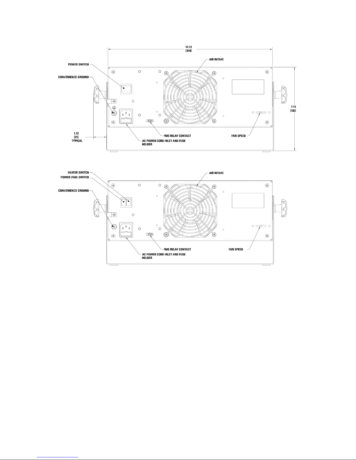
Figure 3. Aerostat XC2 Rear Panel (with heater and without heater)

19-XC2-M-04 Rev 1 5
1.3 Performance
The Model Aerostat XC2 is factory adjusted to meet the
specifications in the centerline static discharge times below:
• 1.0 seconds or less @ 1' (30 cm)
• 2.0 seconds or less @ 2' (60 cm)
• 3.5 seconds or less @ 3' (90 cm)
• 5 seconds or less at @ 4' (122 cm)
These decay times are for directly in-line with the center of the fan,
±1000V to 100V. Measurements were taken at the stated distance
at high fan speed using a charged plate monitor in accordance with
ESD Association Ionization Standard ANSI/ESD STM3.1-2006.
Discharge times may be improved when tested within your
operating environment.
In a humidity-controlled environment, the XC2 will maintain a
balance around zero of ±10V or less. Performance in extreme
environments may vary. When using the optional fan filter, the
performance of the unit will be reduced between 10-40% depending
upon speed of the blower and the distance to the target.
Coverage Area Discharge Time Specification
Discharge times are tested in accordance with ANSI/ESD STM3.1-
2006. Each point identifies the 1000V to 100V discharge times (in
seconds) with high fan/low fan speed across the target area. Times
are slightly higher with 230V/50 Hz unit.
Figure 4. Aerostat XC2 Discharge Times

19-XC2-M-04 Rev 1 6
1.4 Power Requirements
The Aerostat XC2 is powered by an internal universal AC input
power supply with an input line voltage range of 100 to 240 VAC,
50/60 Hz single phase.
Typical maximum current draw for the Aerostat XC2 at high fan
speed:
• 100-240 VAC, 50/60 Hz, 0.5A, 55W max (no heater)
• 100-120 VAC, 50/60 Hz, 3.5A, 420W max (with heater)
• 220-240 VAC, 50 Hz, 1.9A, 460W max (with heater)
Caution:
The use of improper input voltage may result in poor
performance or damage to the unit. Damage caused to the
power supply from operation at levels outside of the specified
limits will void the warranty.
Attention:
L'utilisation d'une mauvaise tension d'entrée peut entraîner de
mauvais résultats ou endommager l'appareil. Les dommages
causés à l'alimentation de fonctionnement à des niveaux en
dehors des limites spécifiées entraînera l'annulation de la
garantie.

19-XC2-M-04 Rev 1 7
2
Installation & Setup
2.1 Box Contents
2.2 Mounting & Placement
2.3 Power Connections

19-XC2-M-04 Rev 1 8
2.1 Box Contents
The Aerostat XC2 is packaged with the following items:
• Mounting Stand (installed on Blower)
• User Manual
• Certificate of Compliance
• Power cord
• Rubber feet for use on mounting stand (4 pieces)
• Cord clamp w/screw
• FMS connector mating plug & crimp contacts

19-XC2-M-04 Rev 1 9
2.2 Mounting & Placement
Initial Operation
Operate the Aerostat XC2 ionizer for an initial 24 hours in the area
of application before any performance measurements are
conducted.
The Aerostat XC2 should be placed approximately 1 to 4 feet (0.3
to 1.3m) from objects to be neutralized or from the critical work
area. Although discharge times are longer the further away the
target area is placed from the XC2, tests show that the XC2 will
ionize the target area at further than 4 feet distance.
The XC2 should be positioned to cover as much of the area as
possible with the ionized air stream. Keep at least a 6 inch
clearance between walls or any objects and the rear of the XC2 to
allow for adequate air intake.
Unit Mounting
The Aerostat XC2 comes with a mounting stand preassembled to
the blower. The mounting stand is designed for a free or fixed
position on a tabletop or workbench and also for mounting to a
fixed surface. Self-adhesive skid-resistant rubber feet are supplied
with the blower and can be installed on the bottom of the stand by
the end-user. Holes in the base of the stand are provided for
securing the XC2 to a fixed location using 5/16" (8 mm) diameter
screw hardware (not provided).
Once the Aerostat XC2 is secured to a surface, the mounting stand
can to adjusted and locked to a desired position. Loosen, but do not
completely remove, the knobs on each side of the blower. Tilt the
XC2 to the desired position so the XC2 ionized airstream is aimed
directly at the target with no intervening grounded objects.
Retighten the knobs to lock the XC2 into place.

19-XC2-M-04 Rev 1 10
2.3 Power Connections
The XC2 accepts universal AC input (100-
230 VAC 50/60 Hz single phase). The XC2
must be grounded for safe and proper
operation. The XC2 is available with different
line cords to meet the main power
connection plug requirements in many areas
of the world. Connect the supplied power
cord to an appropriate 3-terminal grounded
AC power receptacle.
If the XC2 Blower will be installed in an
environment that is electrically noisy, an
additional ground connection can be made
to the blower using the convenience ground
terminal located on the rear panel of the
blower.
A cord clamp is supplied with the blower. Use this cord clamp to
prevent unwanted disconnection of the power cord or for protection
against accidental loosening of the power cord due to vibration.
After connecting the power cord to the power inlet connector, fit the
power cord through the cord clamp and secure the clamp to the
chassis rear panel with the supplied #6 sheet metal screw.
Caution: To insure user safety when operating the Aerostat XC2, do not
point the blower face any lower than 45° from horizontal.
Figure 5. Ground Terminal

19-XC2-M-04 Rev 1 11
Figure 6. Power Cord Clamp
Warning: Do not insert anything within the intake or outlet grills.
Electric shock may result.
Avertissement : N'introduisez rien dans le collecteur d'admission ou de
sortie des barbecues. Provoquer un choc électrique.

19-XC2-M-04 Rev 1 12

19-XC2-M-04 Rev 1 13
3
Operation
3.1 Operating Environment
3.2 Controls & LED Indicators
3.3 Balance
3.4 Alarms
3.5 FMS Relay Contact
3.6 Optional Air Filter

19-XC2-M-04 Rev 1 14
3.1 Operating Environment
Operate the Model Aerostat XC2 in an environment where relative
humidity is 30-60% (non-condensing). The operating temperature
range for the Blower is 50-95°F (10-35°C).
The Model Aerostat XC2 will conform to stated performance
specifications when used in an environment that meets the
cleanliness limits defined by ISO 14644-1 Class 6 (Fed Std. 209E
Class 1000) and if it is serviced according to an appropriate
maintenance schedule.
Other manuals for Aerostat XC2
1
Table of contents
Other Simco-Ion Blower manuals


Popular Blower manuals by other brands


Weed Eater
Weed Eater EBV 215 instruction manual

Gaggenau
Gaggenau AR 410 710 installation instructions

Parkside
Parkside PLS 2600 B2 Translation of the original instructions

Tennant
Tennant S7 Operator's manual

Meyer
Meyer 550 Series Installation, operation & maintenance instructions

Powr-Flite
Powr-Flite WONDER WAND Operator and parts manual