Simco ION Performax IQ Easy Ex User manual

PerformaxIQEasyEx_UM_9752153510_NL_D_GB_FR_V1_4
Performax IQ Easy Ex
Performax IQ Easy Ex Speed
Ionisatiestaaf Anti-static bar
Ionensprühstab Barre antistatique
1180
II 2 GD
Ex mb IIB T4 Gb
Ex mb IIIB T135°C Db
SIMCO (Nederland) B.V.
Postbus 71
NL-7240 AB Lochem
Telefoon +31-(0)573-288333
Telefax +31-(0)573-257319
E-mail gene[email protected]
Internet http://www.simco-ion.nl
Traderegister Apeldoorn No. 08046136
NL Gebruikershandleiding
D Bedienungsanleitung
GB User Manual
1
32
66
FR Mode d’emploi 98

PerformaxIQEasyEx_UM_9752153510_NL_D_GB_FR_V1_4 64
CONTENTS
Preface ............................................................................................................................................. 65
Explanation of symbols ..................................................................................................................... 65
1 Introduction................................................................................................................................... 66
2 Description and Operation ............................................................................................................. 67
3 Safety ............................................................................................................................................ 68
4 Technische specificaties ................................................................................................................. 69
5 Installation .................................................................................................................................... 71
5.1 (Simplified) system overview ................................................................................................................ 71
5.2 Product Check ...................................................................................................................................... 72
5.3 Anti-static bar mounting .......................................................................................................................72
5.4 Mounting brackets (Bracket Bars) .........................................................................................................73
5.5 Montage Performax IQ Easy Ex Speed (slide bracket) ............................................................................ 74
5.6 Dissemble Performax IQ Easy Ex Speed (slide bracket) .......................................................................... 75
5.7 Alternative brackets .............................................................................................................................75
5.8 Connecting the Anti-static bar .............................................................................................................. 75
5.8.1 Connect safety earthing.................................................................................................... 75
5.8.2 Performax IQ Easy Ex Speed connection to the Ex Status module....................................... 76
5.8.3 Connecting the Ex Status Module to the IQ Easy Platform ................................................. 80
5.8.4 Connecting Ex Status Module with double safety to the IQ Easy Platform.......................... 81
6 Commissioning .............................................................................................................................. 81
6.1 Commissioning the anti-static bar through the IQ Easy Platform. ...........................................................81
6.2 Selecting EXPERT mode for setting parameters or maintenance tasks. ................................................... 82
6.3 Calibrating the Performax IQ Easy Ex through the IQ Easy Platform. ...................................................... 82
6.4 Operating modes (expert) ....................................................................................................................83
6.4.1 Operation Mode Manual .................................................................................................. 84
6.4.2 Operation mode CLFB (Closed Loop FeedBack) with IQ Easy sensor .................................... 85
6.5 Anti-static bar Standby & Active and Autorun setting. ...........................................................................85
6.6 Anti-static bar Information parameters (expert mode). ......................................................................... 86
6.7 Switching the bar on/off remotely through the remote on/off input on the Manager or via fieldbus
(expert mode) ............................................................................................................................................ 86
6.8 Datalogging (de-)activation. .................................................................................................................87
6.9 Clean bar warning level setup (expert mode) ........................................................................................ 87
7 Checking the Functionality ............................................................................................................. 87
7.1 Checking neutralization ........................................................................................................................87
7.2 Checking functionalities via the LED’s ................................................................................................... 87
7.3 Functional check via the Manager IQ Easy ............................................................................................. 88
7.3.1 Information tab ................................................................................................................ 88
7.3.2 Graphics tab ..................................................................................................................... 89
7.3.3 Action log tab ................................................................................................................... 89
7.3.4 Data log tab ..................................................................................................................... 89
7.4 Causes for overloading ......................................................................................................................... 89
8 Maintenance ................................................................................................................................. 90
8.1 Regular cleaning of the anti-static bar ................................................................................................... 90
8.2 Cleaning of a heavily contaminated anti-static bar ................................................................................ 90
9 Faults ............................................................................................................................................ 90
10 Repairs ........................................................................................................................................ 92
11 Disposal....................................................................................................................................... 92
Replacement parts ........................................................................................................................... 93
Declaration of Conformity ................................................................................................................ 95
PerformaxIQEasyEx_UM_9752153510_NL_D_GB_FR_V1_4 65
GB
Preface
This manual concerns the installation and use of an ionization system
Performax IQ Easy Ex and Performax IQ Easy Ex Speed.
Should there be any reference in this manual to an anti-static bar then it is with reference to the
Performax IQ Easy Ex or Performax IQ Easy Ex Speed.
This manual must be available at all times to staff operating the equipment.
Read through the entire manual before installing and commissioning the product.
Follow the instructions set out in this manual to ensure proper operation of the product and to
retain your entitlement under the guarantee. The terms of the guarantee are set out in the
Simco-Ion Netherlands General Terms and Conditions of Sale.
Explanation of symbols
Warning
Indicates special information to prevent injury or significant damage to the
product or the environment.
Attention
Important information for making the most efficient use of the product
and/or for preventing damage to the product or the environment.
[ ] If icons are shown between brackets [ ], this means, depending on where
you are in the menu, it may be necessary to first select the icons between
brackets [ ] before you can go to the desired page where the follow-up
instruction are given.
Using these buttons you can scroll through the various pages.
The manual is described with the default state of the Manager: Run state Color Green =
NO.
PerformaxIQEasyEx_UM_9752153510_NL_D_GB_FR_V1_4 66
1 Introduction
The Performax IQ Easy Ex and Performax IQ Easy Ex Speed static bars are designed to
neutralize electrostatically charged surfaces and may be used in certain hazardous areas (see
also Section 3, Safety).
The main difference between these two static bars is their recommended use;
The Performax IQ Easy Ex is suitable for general applications, the Performax IQ Easy Ex
Speed is suited for high web speeds, close to the material to be discharged.
Both static bars are equipped with an integrated high voltage power supply, emitters and a
status LED.
The Performax IQ Easy Ex and Performax IQ Easy Ex Speed are connected via a cable with 5
conductors to the IQ Easy platform. With the IQ platform the anti-static bar can be controlled
and read out centrally and remotely. Using the IQ Easy platform, the status of the bar can be
logged making quality management easier.
The Performax IQ Easy Ex is optimally deployed between 100 and 300 mm away from the
material at material speeds below 500 meters per minute and is available in effective lengths of
270 through to 2790 mm in increments of 180 mm.
For material speeds exceeding 500 meters per minute and / or material distances between 50
and 300 mm the Performax IQ Easy Ex Speed is recommended. This is available in effective
lengths from 90 through to 2790 mm, in increments of 60 mm.
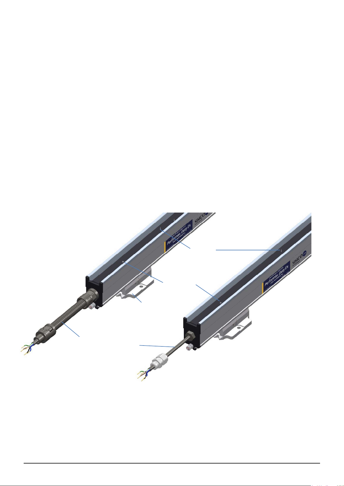
Image 1.1: Connection side Performax IQ Easy Ex and Performax IQ Easy Ex Speed
Mounting bracket
Emitters
Status LED
Fixed connecting cable,
with protective hose
(standard) or without
protective hose
(optional).
PerformaxIQEasyEx_UM_9752153510_NL_D_GB_FR_V1_4 67
GB
2 Description and Operation
The 24 V DC power supply is converted in the anti-static bar into a positive and negative high
voltage.
The high voltage generates an electrical field at the emitters of the anti-static bar, which causes
the air molecules around the emitters to be converted into positive and negative ions. When an
electrostatically charged material comes within working distance of the anti-static bar, the ions
from the anti-static bar are exchanged with the charged material until the material is neutralized.
You can see via the status LED if the anti-static bar is in operation and if it is overloaded.
In addition, through the Manager IQ Easy divers parameters, limit values and information
concerning the functioning (efficiency) can be recorded and logged. To learn more refer also to
the user manual of the Manager IQ Easy.
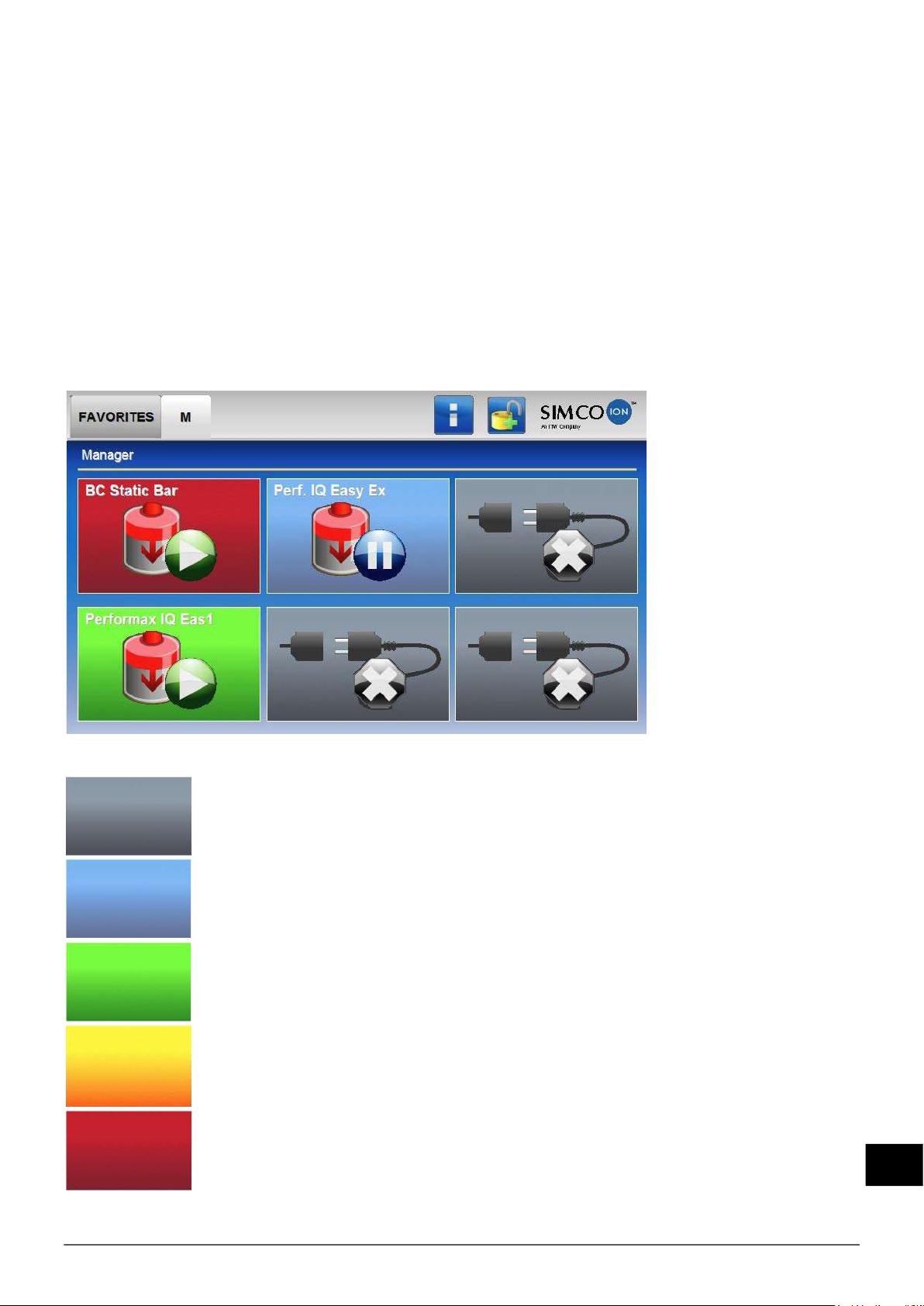
The background color of the anti-static bar icon shows the status of the anti-static bar, where:
Inactive or no communication
Active and operating OK, without warnings or alarms
Standby, waiting for start command
Active, but with a warning
Active, but with an alarm

PerformaxIQEasyEx_UM_9752153510_NL_D_GB_FR_V1_4 68
3 Safety
The following safety guidelines must be observed in order to prevent physical injury and
damage to objects or the anti-static bar itself.
Warning:
- The anti-static bar is only intended for neutralizing electrostatically charged surfaces.
- Before using the Performax IQ Easy Ex Speed in an explosive hazardous area, check
whether it is permitted to be used in the zone classification of the hazardous area.
- The anti-static bar is suitable for ATEX II 2GD.
The anti-static bar should only be used in non-mining applications and has a “high
protection” grade:
The anti-static bar may be used in gas zones 1 and 2 and is suitable for gas groups
IIA and IIB.
The anti-static bar can be used in dust zones 21 and 22 and is suitable for use
with dust groups IIIA and IIIB.
The maximum “surface temperature “of the anti-static bar is limited to a max. 135ºC.
- The Performax IQ Easy Ex Speed should not be used in environments containing dusts
which are electrically conductive i.e. having an electrically resistivity less than 1000 ohm
meters.
- The Performax IQ Easy Ex Speed should not be used in the presence of dust having ignition
energies less than 0,2mJ.
- Mount the Performax IQ Easy Ex Speed in a manner that provides complete protection
against impact.
- Fit the connecting cable of the Performax IQ Easy Ex Speed in such a way there is no
possible mechanical damage.
- The Performax IQ Easy Ex should be mounted at a distance of 100 to 300 mm.
- The Performax IQ Easy Ex Speed should be mounted at a distance of 50 to 300 mm.
- To ensure the safe operation, the working temperature should be kept below 40ºC.
- Electrical installation should be done only by a skilled electrical engineer and in accordance
with all national and local regulations.
- Use the Performax IQ Easy Ex Speed always in combination with an Ex Status Module.
The Ex Status Module includes the necessary 0,5AT fuse with a rupturing capacity of 1500A
(70-007-33/0.5A, Siba), which should ensure safety in the event of an overload / short circuit.
Should this fuse be defective, it must be replaced with a fuse with the same properties.
- Only the Performax IQ Easy Ex Speed with fixed wiring should be installed in Ex-zone
environments. The Ex Status Module, with any other connected devices should be mounted
outside the hazardous zone.
- The equipment must be properly earthed. Earthing is essential to ensure safe operation and
to prevent electrical shock when touched.
- When working on the equipment, the equipment must be disconnected from the power
supply.
- The emitters are sharp and can cause injury.
- During the ionization process a small amount of ozone is produced. The concentration of
ozone around the emitters is dependent on many factors, such as the amount of space
around the anti-static bar and air circulation. Due to which no general value for the ozone
concentration can be given.
-
electrically safe to touch.
PerformaxIQEasyEx_UM_9752153510_NL_D_GB_FR_V1_4 69
GB
Attention:
- The warranty for the device is void in the event that modifications, adjustments, etc. have
been made or non-original parts are used for repairs without prior written approval.
4 Technical specifications
Power Requirements
Supply Voltage 24 V DC nominal
Primary Fuse 0,5 AT, Type: 70-007-33/0.5A, Siba
This fuse has a rupturing capacity of min 1500A (breaking
capacity).
This fuse is present in the delivered Ex Status Module by Simco-
Ion.
Current consumption Max. 0,4 A DC
Connection Cable 5 x 0,34 mm2
Max. total cable length @ supply 24V DC ± 2% 24V DC ± 5% 24V DC ± 10%
Max. cable resistance per wire 3,125 2,25 0,75
Standard Simco 5x0,34 mm2&
M12 Male-Female cable
62,5m 45m 15m
Type power supply 100-240 V AC
Manager IQ Easy
100-240 V AC
Extension IQ Easy
Input
Remote on/off 10 – 30 V DC nominal (Ri >10k)
Activation time 30 ms
Output
Output voltage emitters Max. 9 kV positive and negative
Current per emitter to earth Max. 50 µA
High voltage OK (HV OK) Supply voltage -1 V, max. 50 mA
Environment
Usage Industrial, indoor usage
Ex environment
ATEX II 2 GD (see Chapter 3)
Ex mb IIB T4 Gb
Ex mb IIIB T135°C Db
Protection class IP66
Ambient temperature 0 - 40°C
Max. Temperature enclosure 135°C
Material speed Performax IQ Easy Ex 0 – 500 m/min
Performax IQ Easy Ex Speed >500 m/min
Working distance Performax IQ Easy Ex
Performax IQ Easy Ex Speed
100 - 300 mm
50 – 300 mm
Local signaling
2-Color LED Continual: Blinking:
Green In use Stand-by
Red Overloaded No communication
See chapter 7 for more info

PerformaxIQEasyEx_UM_9752153510_NL_D_GB_FR_V1_4 70
Mechanical
Effective length Performax IQ Easy Ex 270 - 2790 mm
in increments of 180 mm
Performax IQ Easy Ex
Speed
90 - 2790 mm
In increments of 60 mm
Dimensions exclusive
Mounting brackets
Tot. length= Eff. length + 250 mm (with protective hose)
Tot. length= Eff. length + 180 mm (without protective hose)
Width 30 mm
Height 52 mm
Weight 2,2 kg/m
Enclosure Aluminum / PA6 / PUR
Universal Mounting brackets PA66/6
Image 4.1.1: Dimensions Performax IQ Easy Ex (Speed)

PerformaxIQEasyEx_UM_9752153510_NL_D_GB_FR_V1_4 71
GB
5 Installation
Warning:
-Before using the Performax IQ Easy Ex Speed in an explosive hazardous area, check
whether it is permitted to be used in the zone classification of the hazardous area.
-Mount the Performax IQ Easy Ex Speed in a manner that provides complete protection
against impact.
-Only the Performax IQ Easy Ex Speed with fixed wiring can be installed in the
hazardous area. The Ex Status Module and any other connected devices must be
mounted outside the Ex zone.
-Electrical installation and repairs must be done only by a skilled electrical engineer
and in accordance with all national and local regulations.
-When working on the equipment, the equipment must be disconnected from the
power supply.
-The equipment must be properly grounded. Earthing is necessary to ensure safe
operation and to prevent any electrical shock when touched.
-Connect the ground terminal on the anti-static bar to a grounded part of the machine
with a wire of a minimum size of 4mm2.
-Use the Performax IQ Easy Ex Speed always in combination with the Ex Status
Module and IQ Easy Manager and / or Extension IQ Easy.
The anti-static bar is powered and controlled via the IQ Easy Platform.
See the list of spare parts and accessories for the available IQ Easy Managers and Extension
IQ Easy.
5.1 Simplified system overview
A Status Module is needed for each anti-static bar. The anti-static bar is connected to the Status
Module through the wires at a connector block in the Status Module. For instructions, see 5.8.2.
The Status Module is connected with the Manager IQ Easy.
5.2 Product Check
- Make sure the equipment is undamaged and that the correct version is received.
- Make sure the packing slip corresponds with the data of the received product.
Should you have any problems and / or questions, please contact Simco-Ion or the local agent
in your area.
Image 5.1.1: System overview
PerformaxIQEasyEx_UM_9752153510_NL_D_GB_FR_V1_4 72
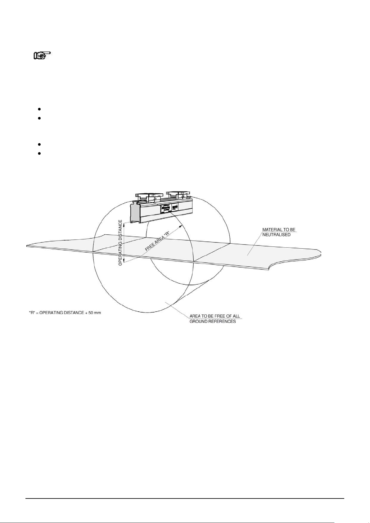
5.3 Anti-static bar mounting
Attention:
- Any conductive machine parts in the vicinity of the anti-static bar will negatively affect
its performance. For the best results the anti-static bar should be mounted in
accordance with Image 5.3.1
- Mounting the anti-static bar:
Place just before the location where the static electricity problem occurs.
Place with an optimal distance from the material that should be neutralized:
o100 - 300 mm (Performax IQ Easy Ex)
o50 - 300 mm (Performax IQ Easy Ex Speed)
With the emitters in the direction of the material to be neutralized.
Ensure that no material can come between the emitters and the material to be neutralized
Attach the cable properly into the machine to prevent mechanical damage (suitable hose
and clamps can be ordered separately).
Image 5.3.1: Optimal position Performax IQ Easy Ex and Performax IQ Easy Ex Speed
PerformaxIQEasyEx_UM_9752153510_NL_D_GB_FR_V1_4 73
GB
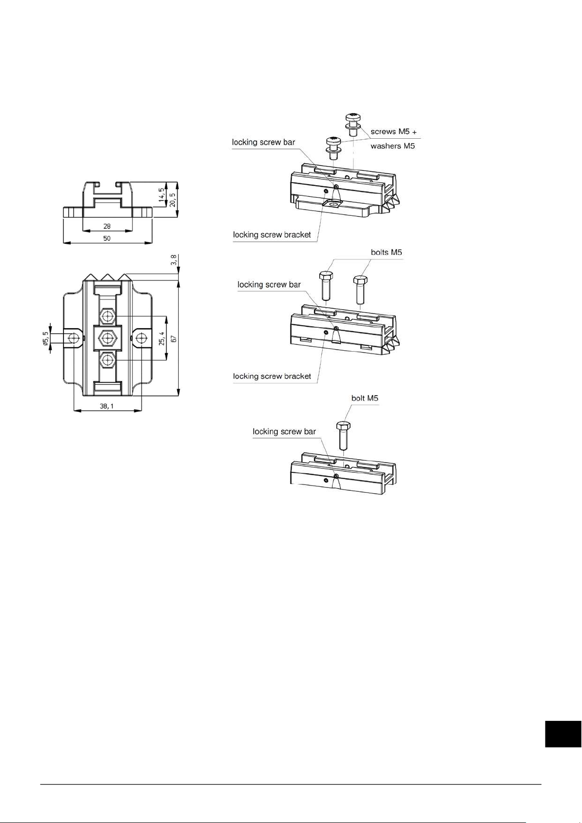
5.4 Mounting brackets
The anti-static bars are provided with at least two mounting brackets with which the anti-static
bars can be attached in many different ways.
Image 5.4.1: Mounting brackets Performax IQ Easy Ex Speed dimensions and mounting options
PerformaxIQEasyEx_UM_9752153510_NL_D_GB_FR_V1_4 74
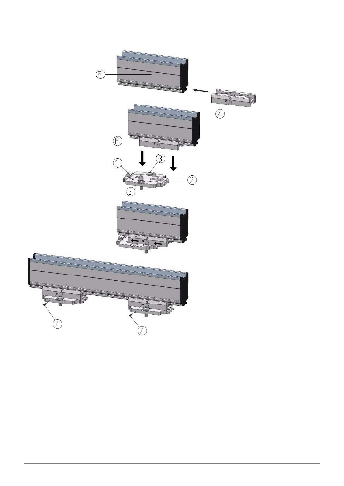
5.5 Montage Performax IQ Easy Ex Speed (slide bracket)
Image 5.5.6: Fixing the anti-static bar with mounting brackets
- Mount the mounting feet (1) on the machine, with the triangles (2) pointing in the same
direction. Use suitable M5-fixing materials (3).
- Slide the brackets (4) on the anti-static bar (5).
-Place the anti-static bar with brackets on the mounting feet and push the brackets (4) in the
opposite direction of the three triangles.
- Lock the bracket (4) by tightening at least one of the two set screws (7) (a screw is on both
sides).
- Position the ionization points above the material to be neutralized.
- Secure the anti-static bar (5) with a screw (6).

PerformaxIQEasyEx_UM_9752153510_NL_D_GB_FR_V1_4 75
GB
5.6 Dissemble Performax IQ Easy Ex Speed (slide bracket)
- Remove the connection cable from the Ex Status Module.
- Unscrew the set screw (no. 6) from the brackets (see Image 5).
- Slide the anti-static bar with brackets from the mounting feet, in the direction of the three
triangles (Mounting method) till it stops, pull the anti-static bar perpendicular to the mounting
feet.
5.7 Alternative brackets
As an alternative to the plastic brackets, 2 additional stainless steel types are available:
5.8 Connecting the Anti-static bar
Warning:
- Observe the warnings at the beginning of this chapter.
- The Ex Status Module must be mounted outside the Ex zone.
-Use the Performax IQ Easy Ex Speed always in combination with an Ex Status Module.
Never connect the Performax IQ Easy Ex Speed directly to the power supply, this is
because the Ex Status Module contains the required fuse (0,5 AT / 1500A breaking
capacity)
5.8.1 Connect safety earthing
Connect the anti-static bar with an M4 eyelet and a grounding wire of at least 4 mm² to a
grounded machine part or grounded terminal.
Image 5.8.1.1: Connecting grounding
Image 5.7.1: Bracket T-slot stainless steel
Image 5.7.2: Bracket thread M6x35 stainless steel

PerformaxIQEasyEx_UM_9752153510_NL_D_GB_FR_V1_4 76
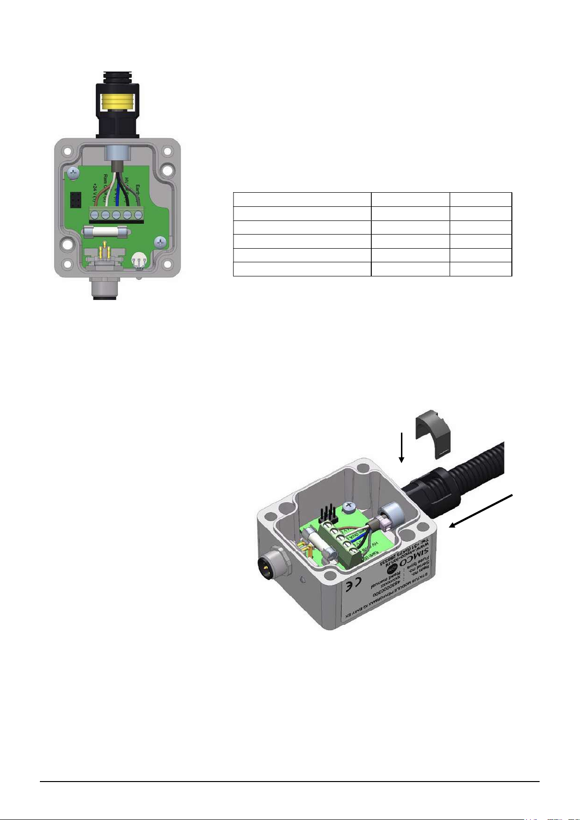
5.8.2 Performax IQ Easy Ex Speed connection to the Ex Status module
Mount the Status Module at a place outside the EX-Zone.
Use 2 bolts or screws of a max. 4 mm. Take into account 15 cm of space for the cable
connection from the EX anti-static bar on one side, and the cable with connector on the other
side. Also note that the LED next to the connector should be visible in order to view the status of
the anti-static bar.
For an EX-bar with protective hose:
- When needed: cut the 5-wire cable to the desired length.
- Cut the protective hose on the needed length. This is the cable length - 32mm (see image
5.8.2.3).
- Push a yellow seal on the protective hose on the bar side. (see image 5.8.2.4).
- Run the cable through the protective hose with the yellow seal at the bar side.
- Push the protective hose into the fitting of the ionization bar until the yellow seal is no longer
visible (see image 5.8.2.5).
- Insert the grey clip into the fitting with the slot facing the outside, so it can be removed with a
screw driver if required (see image 5.8.2.6).
- Push a yellow seal on the protective hose on the status module side
- When needed: strip the cable according picture 5.8.2.7 mount proper ferrules (within
shipment) to the end of the wires.
- Screw the fitting into the Status Module and run the stripped cable through the fitting.
- Push the protective hose into the fitting of the ionization bar until the yellow seal is no longer
visible (see image 5.8.2.8).
- Insert the grey clip into the fitting with the slot facing the outside, so it can be removed with a
screwdriver if required.
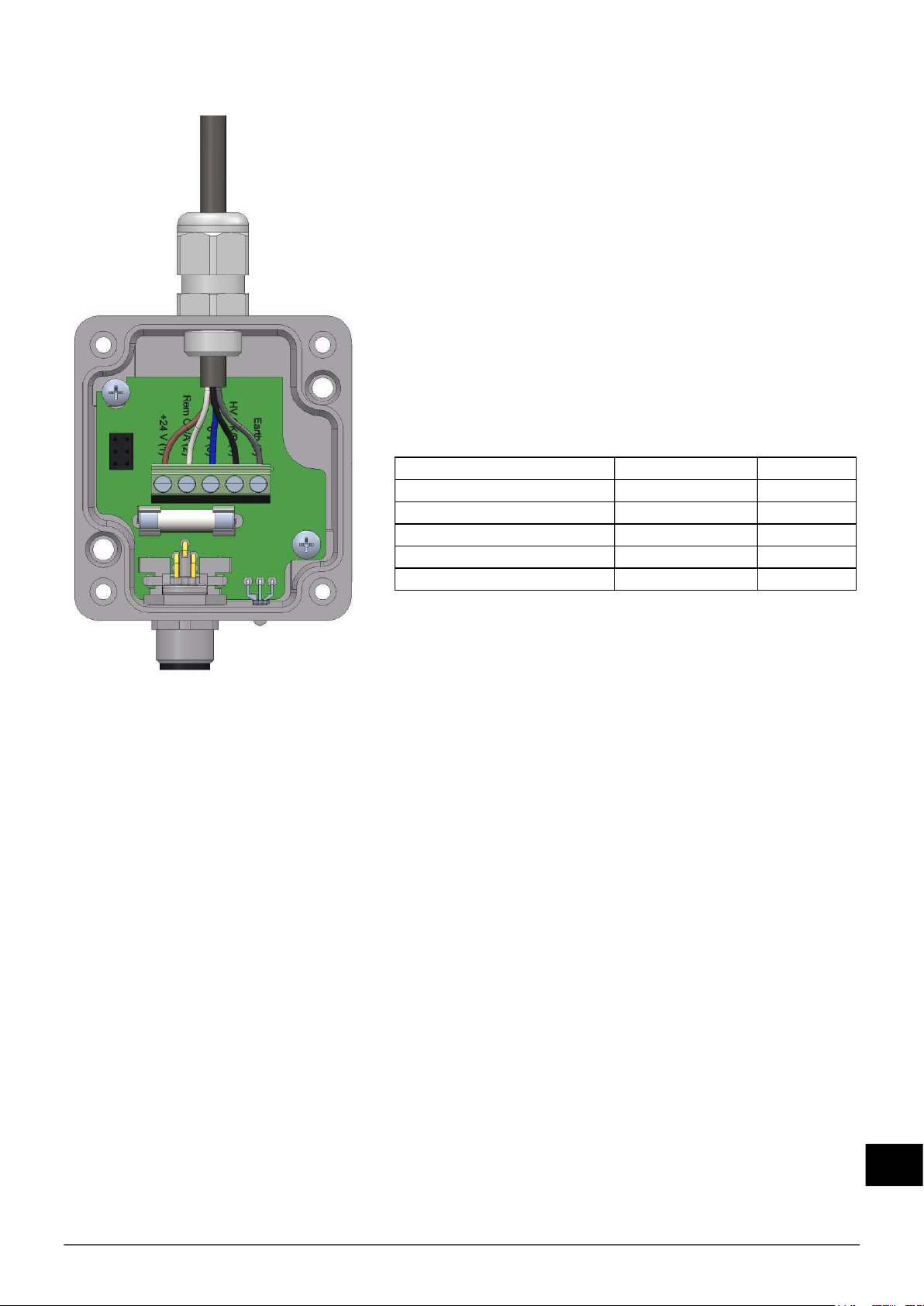
- Connect the cable to the pcb of the Status Module.
Remove the cover of
the Status module
and remove the
blind plug.
Image 5.8.2.1: Prepare connection Status Module
Image 5.8.2.2: Sizes of fixing holes Status Module
LED

PerformaxIQEasyEx_UM_9752153510_NL_D_GB_FR_V1_4 77
GB
Image 5.8.2.3 Length protective hose
Image 5.8.2.4: Yellow seal on protective hose
Image 5.8.2.5: Protective hose in fitting Image 5.8.2.6: Clip in fitting
Image 5.8.2.7: Strip the cable
Image 5.8.2.8: Mounting of fitting on Status Module
PerformaxIQEasyEx_UM_9752153510_NL_D_GB_FR_V1_4 78
Push the protective hose into the Status Module until the yellow
seal is no longer visible (1). Then insert the grey clip in the fitting
with the slot facing the outside (2),
so it can be removed with a screw driver if required.
Then replace the cover and fasten with the screws.
Colour: Connection: Number:
Brown + 24 V 1
White A 2
Blue 0 V 3
Black B 4
Yellow/green or grey Earth 5
Image 5.8.2.10: Fixing a protective hose to the fitting
1
2
Connect the cable according to the table below
:
Image 5.8.2.9: Connection wiring Performax Easy EX Speed with the Status Module
PerformaxIQEasyEx_UM_9752153510_NL_D_GB_FR_V1_4 79
GB
Colour: Connection: Number:
Brown + 24 V 1
White A 2
Blue 0 V 3
Black B 4
Yellow/green or grey Earth 5
For an EX-bar with cable without protective hose:
When needed: cut the cable to the desired length, strip
the cable according to figure 5.2.8.7 and mount proper
ferrules to the end of the wires.
Turn the gland in the Status Module and run the cable
through the gland. Tighten the clamp ring of the bolt for
good sealing and relief from straining.
Connect the cable according to the table below, place
the cover and screw tightly.
Image 5.8.2.11: Wiring connection Performax Easy EX (Speed) with Status Module

PerformaxIQEasyEx_UM_9752153510_NL_D_GB_FR_V1_4 80
5.8.3 Connecting the Ex Status Module to the IQ Easy Platform
- Connect the Ex Status Module via a 1:1 M12 connection cable, Male-Female, 5 pins to one
of the outputs of the Manager IQ Easy or Extension IQ Easy.
The standard M12 connector can be connected during operation of the IQ Manager Easy.
Hence, it doesn’t need to be switched off!
Image 5.8.3.2: Wiring connectors
brown
blue (GND)
yellow/green or grey
brown
black
whitewhite
yellow/green or grey
black
blue
Ex Status Module)
(cable side view)
Female connector M12
Manager / Extension IQ Easy
(cable side view)
Male connector M12
2
white
1
brown 5
yellow/green
or grey
3 blue
4 black
2
white
3 blue
5
yellow/green
or grey
1
brown
4 black
Image 5.8.3.1: Connecting Status Module to Manager IQ Easy

PerformaxIQEasyEx_UM_9752153510_NL_D_GB_FR_V1_4 81
GB
5.8.4 Connecting Ex Status Module with double safety to the IQ Easy Platform
In the event that power supply from the anti-static bar by means of a double safety connection is
required, it can be arranged as follows:
6 Commissioning
Attention:
- The anti-static bar does not work if the emitters are covered.
-Remove the protective cover. The cover is used solely to protect the emitters during
transport and mounting.
6.1 Commissioning the anti-static bar through the IQ Easy Platform.
In the event that the message ”Undefined param” appears on the info screen from the
bar on the Manager or when the bar is not reqognized, the Manager must be updated with
the latest software.
Download the latest software-version via www.simco-ion.co.uk/software
and follow the "Upgrade" instructions as described in the Manager manual.
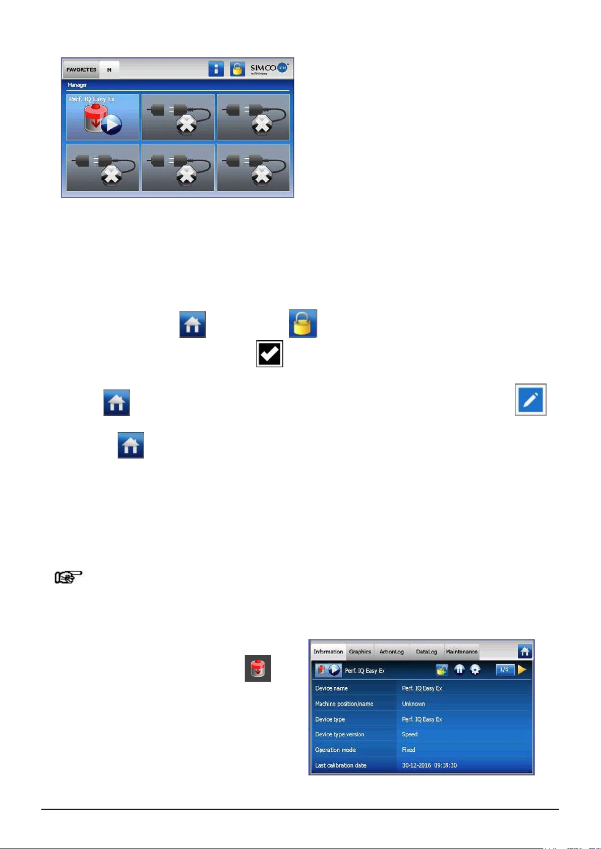
-When the M12 connection cable connects the anti-static bar and the IQ Easy platform,
communication will be established automatically, this is indicated by the flashing status of the
LEDs.
By default, the bar will activate after all information has been gathered by the Manager. This
is indicated by the background color changing to Blue.
See also the user manual for the Manager IQ Easy for a general explanation.
Image 5.8.4.1: Connecting Status Module to Manager IQ Easy with safety relays
PerformaxIQEasyEx_UM_9752153510_NL_D_GB_FR_V1_4 82
The anti-static bar will now ionize.
6.2 Selecting EXPERT mode for setting parameters or maintenance tasks.
In order to set parameters and carry out maintenance, you need expert user privileges. A
password may be required. For a detailed description, please refer to chapter 6.4 from the
Manager IQ Easy manual.
Once logged in at this user level, you will remain at this level until a new level is selected.
-Go to the main screen select settings and choose expert.
-Enter the password and confirm with or return directly to the system settings page of
the Manager, if no password is required.
-Click on and go to the device to check or change the parameters by clicking on
behind the parameter or desired action.
-By clicking you will return to the main screen.
6.3 Calibrating the Performax IQ Easy Ex through the IQ Easy Platform.
The anti-static bar should be calibrated when:
- It is first commissioned,
- The position of the bar is changed
- Following cleaning.
Attention:
Make sure that the bar is mounted in the final position and that the conveyor or object to be
neutralized is in position but not moving (standing still).
.
-Go to user level expert section – see 6.2
- Go to the device menu by clicking
This manual suits for next models
1
Table of contents


