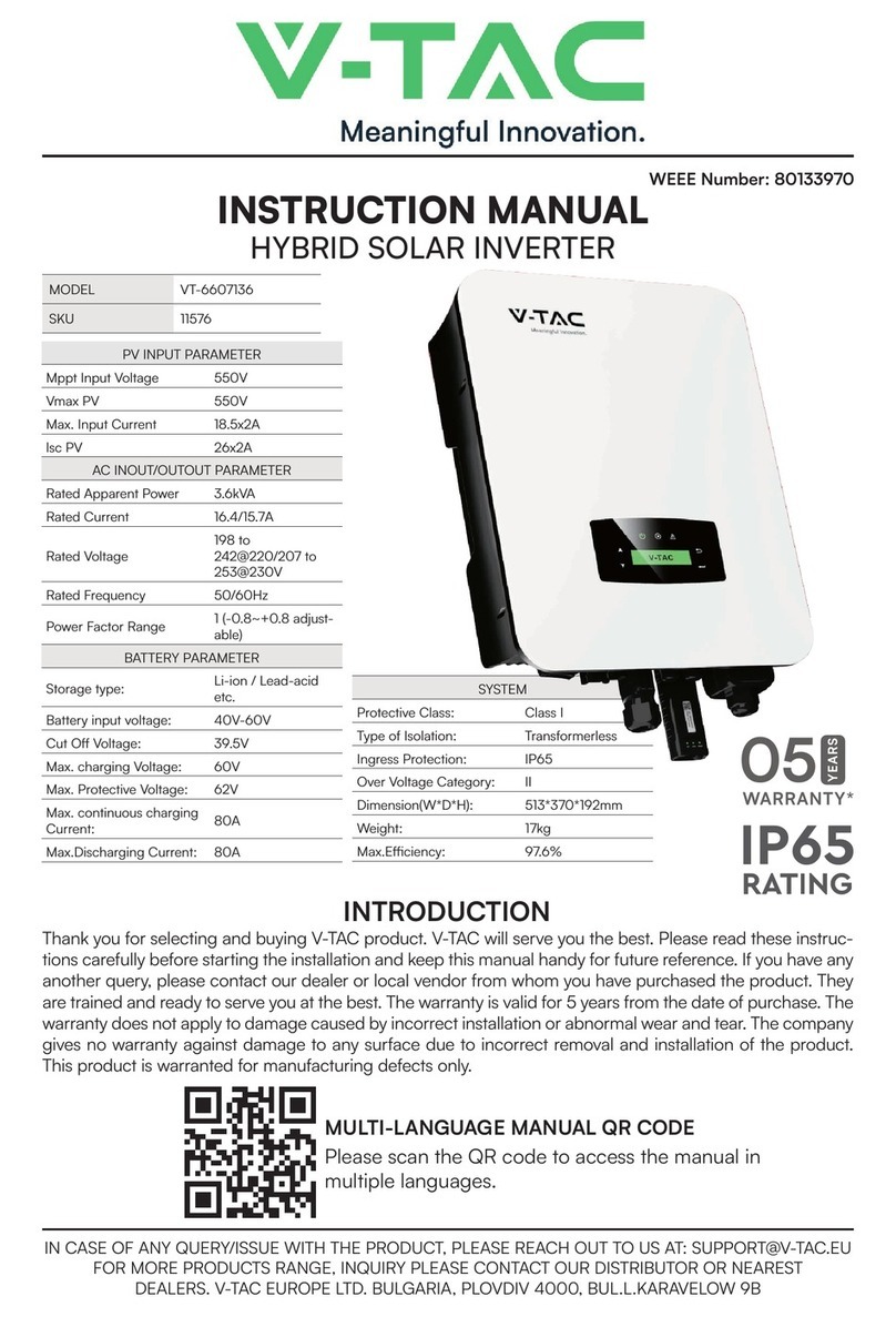
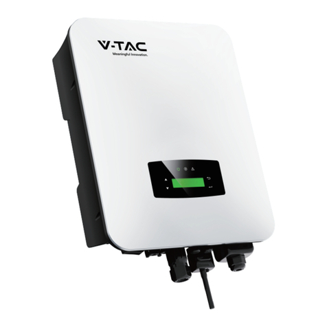
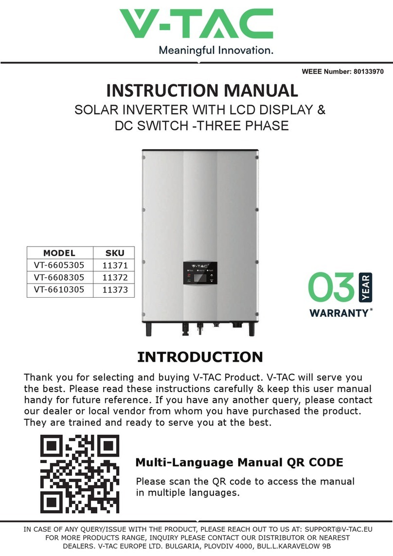
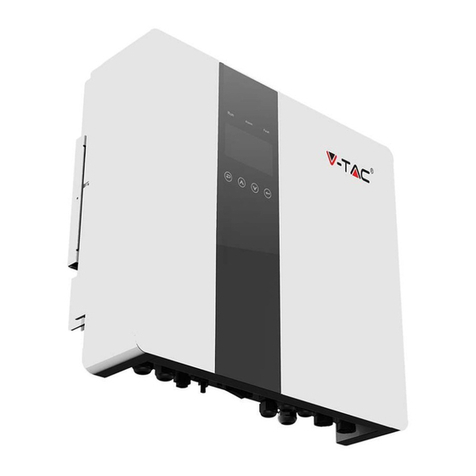
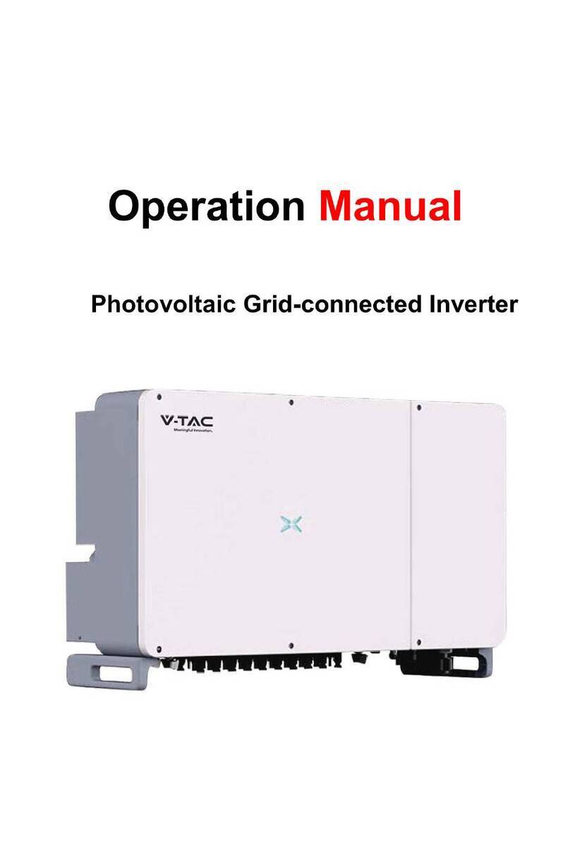
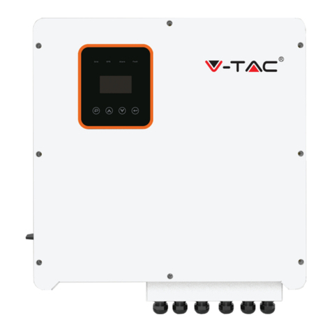
V-TAC AF6K-SL User manual

INSTRUCTION MANUAL
HYBRID SOLAR INVERTER
IN CASE OF ANY QUERY/ISSUE WITH THE PRODUCT, PLEASE REACH OUT TO US AT: SUPPORT@V-TAC.EU
FOR MORE PRODUCTS RANGE, INQUIRY PLEASE CONTACT OUR DISTRIBUTOR OR NEAREST
DEALERS. V-TAC EUROPE LTD. BULGARIA, PLOVDIV 4000, BUL.L.KARAVELOW 9B
Thank you for selecting and buying V-TAC Product. V-TAC will serve you
the best. Please read these instructions carefully & keep this user manual
handy for future reference. If you have any another query, please contact
our dealer or local vendor from whom you have purchased the product.
They are trained and ready to serve you at the best.
INTRODUCTION
Multi-Language Manual QR CODE
Please scan the QR code to access the manual
in multiple languages.

WARNING
1. Please make sure to turn off the power before starting the installation.
2. Installation must be performed by a qualified electrician.
1. All work on the inverter must be carried out by qualified electricians.
2. The PV panels and inverter must be connected to the ground.
3. Do not touch the inverter cover until 5 minutes after disconnecting both DC and AC
power supply.
4. Do not touch the inverter enclosure when operating, keep away from materials that may
be affected by high temperatures.
5. Please ensure that the used device and any relevant accessories are disposed of in
accordance with applicable regulations.
6. VTAC inverter should be placed upwards and handled with care in delivery. Pay attention
to waterproof. Do not expose the inverter directly to water, rain, snow or spray.
7. Alternative uses, modifications to the inverter not recommended. The warranty can
become void if the inverter was tampered with or if the installation is not in accordance
with the relevant installation instructions.
EXPLANATION OF SYMBOL
20
PAP
Symbol Explanation
CE mark.
The inverter complies with the requirements of the applicable CE
guildlines.
Beware of hot surface
The inverter’s housing may reach uncomfortably hot 60°C (140°F)
under high power operation. Do not touch the inverter enclosure when
operation.
Danger of high voltages. Danger to life due to high voltages in the
inverter!
Refer to manual before service
Do not dispose of this device with the normal domestic waste.
Important notes
Read all instructions carefully. Failure to follow these instructions,
warnings and precautions may lead to device malfunction or
damage.
Residual power discharge
Do not open the inverter cover until 5 minutes after disconnection
both DC and AC power supply.

INTRODUCTION
The VTAC Hybrid Solar Inverter series hybrid inverters are designed to increase energy
independence for homeowners. Energy management is based on time-of-use and demand
charge rate structures, significantly reduce the amount of energy purchased from the public
grid and optimize self-consumption.
OPERATION MODES
Self-Use
The Self-Use mode is for the regions with low feed-in tariff and high electricity prices. The
energy produced by the PV system is used to optimize self-consumption needs. The excess
energy is used to recharge the batteries, any remaining excess is then exported to the grid.
Note: Advance Setting
• When select 0 W under P_Feed menu, the inverter will export zero energy
to the grid.
• When select xx W under P_Feed menu, the inverter will export customized
energy to the grid.
Wind
Turbines
PV Array
Grid
Meter
Hybrid Inverter
Storage Baery Generator Cri�cal LoadSmart Load Load
TV
TV
Energy flow:
PV → Load → Battery → Grid
1
2
3

The Time of Use mode is designed to reward customers who do their part to reduce demand
on the electric grid, particularly during peak usage periods. Use most of your electricity
from PV energy and during off-peak time periods, and you could significantly lower your
monthly bill.
Time of Use
A. Charge Setting
B. Discharge
C. Forbidden Discharge
4 periods of time charge setting.
Energy flow:
PV -> Battery -> Load -> Grid
4 periods of time discharge setting, the battery
will be charged firstly.
Energy flow:
PV -> Battery -> Load -> Grid
4 periods of time charge setting.
Energy flow:
PV and Grid -> Battery -> Load
Note:
After select AC charge, when PV have no
sufficient power, AC will also charge the battery.
TV
2
1
3
TV
2
1
PV Charge Mode
4 periods of time discharge
setting.
Energy flow:
Battery and PV -> Load -> Grid
AC Charge Mode
TV
1
2
TV
1
2
TV
2
1
3

Selling First
Back-Up
When the grid fails, the system
will automatically switch to
Back-Up mode. The
back-up loads can be supplied
by both PV and battery energy.
Energy flow:
PV and Battery -> Load
The Selling First mode is
suitable for the regions with
high feed-in tariff.
Energy flow:
PV -> Load -> Grid -> Battery
TV
1
TV
1
3
76 9 10
5
Monitoring
Quick
Installation
Instructions
54
1
Quick
Installation
Instructions
Warranty
Card
2
12 5
14
13
2019
11
Certificate
Of Inspection
17
515 16 18
8
TV
1
3
2

TERMINAL OF PV INVERTER
PRODUCT OVERVIEW
No. Qty Items No. Qty Items
1 1 Hybrid Inverter 11 1Grounding Terminal
2 1 Certificate Of Inspection 12 1Wall Mounting Bracket
3 1 Quick Installation Instructions 13 1Ba�ery Connector
4 1 Warranty Card 14 1Monitor Module
5 1 Monitoring Quick Installation Instructions 15 1/2 DC Connector
6 1 CT 16 3Mounting Bracket Screw
7 4 AC Wiring Cover Screw 17 3Plastic Expansion Tube
8 1 Security Screw 18 1Smart Meter (Opitional)
9 4 AC Wiring Terminal 19 1AC Waterproof Cover
10 2Communication Connectors 20 1Communication Adapter
Note:
DC connectors Qty.: VT-66036103 is 2 pairs.
370mm
513mm
192mm

INVERTER TERMINALS
Mounting Location
The inverters are designed for indoor and outdoor installation (IP65), to increase the
safety, performance and lifespan of the inverter, please select the mounting location
carefully based on the following rules:
• The inverter should be installed on a solid surface, far from flammable or
corrosion materials, where is suitable for inverter’s weight and dimensions.
• The ambient temperature should be within -25°C ~ 60°C (between -13 °F and 140°F).
• The installation of inverter should be protected under shelter. Do not expose
the inverter to direct sunlight, water, rain, snow, spray lightning, etc
62
3
1 4 5
7
No. Items
1DC Switch
2DC Connectors ( + ) For PV Strings
3DC Connectors ( − ) For PV Strings
4Ba�ery Port
5Communication Port
6AC Port & EPS Port
7Monitor Module Port

The inverter should be installed vertically on the wall, or lean back on plane
with a limited tilted angle. Please refer to below picture.
Leave the enough space around inverter, easy for accessing to the inverter,
connection points and maintenance.
<15°
>0°
Max
300mm
300mm 300mm
500mm
50mm

MOUNTING
Step 1
Step 3
Step 2
264mm
219mm
17mm
Security
screw

ELECTRICAL CONNECTION
COMMUNICATION ADAPTER PIN ASSIGNMENT
Grid
Wind Turbines PV Array
Smart meter
Crical LoadSmart Load
Load
TV
12345678
Note:
For diesel generators or multi-machine parallel use, please contact the
manufacturer, and provide installation and operation instructions separately
No. COM1 Items
1NTC+ Meter 485A
2NTC- Meter 485B
3Dry Contact BAT 485A
4Dry Contact BAT CANH
5DRM BAT CANL
6DRM BAT 485B
7485A CTU
8485A CTN

PV CONNECTION
The VT-66036103 series hybrid inverter has two MPPT channels, can be connected with
two strings of PV panels. Please make sure below requirements are followed before
connecting PV panels and strings to the inverter:
• The open-circuit voltage and short-circuit current of PV string should not exceed the
reasonable range of the inverters.
• The isolation resistance between PV string and ground should exceed 300 kΩ.
• The polarity of PV strings are correct.
• Use the DC plugs in the accessory.
• The lightning protector should be equipped between PV string and inverter.
• Disconnect all of the PV (DC) switch during wiring.
Warning:
The fatal high voltage may on the DC side, please comply with electric
safety when connecting.
Please make sure the correct polarity of the cable connected with inverter,
otherwise inverter could be damaged.
STEP 1:
STEP 2:
Note:
Please use PV connector crimper to pinch the point of the arrow.
You’ll hear click sound when the connector assembly is correct.
MC
MC
!
Note:
PV cable suggestion Cross-section 4mm²

VT-6607106 hybrid inverters are compatible with lithium battery. For lead acid
battery or batteries with other brands, please confirm with local distributor or
VTAC for technical support.
BATTERY CONNECTION
Note:
Set battery type and manufacturer, please refer to Chapter 5.3.
BMS(Battery Management System)communication is needed
between inverter and battery.
Note:
Battery cable suggestion Cross - section 8-10 AWG
Please make sure the battery polarities are correct.
Battery cable
19±1mm
STEP 3:
STEP 1:

STEP 6:
Insert the battery connector into the
inverter, if hear a “click”, it means the
battery connection is finished.
STEP 5:
Use an open-end wrench to
tighten the waterproof lock.
STEP 3:
Insert the wire harness into
the terminals according to “+”
and “-” polarity, make the
insulated terminals parallel
with the terminals , the
crimping screw torque is
2.0±0.1N.m
STEP 2:
Pass the crimped battery harness through
the waterproof connector and the cover.
STEP 4:
A “click” sound will be
heard when the connector
assembly is correct.

4 5
BAT-CAN/RS485
CAN/RS485
Lithium
BAT-NTC
NTC
3-8
1
2
PIN Assignment
NTC-
NTC+
RJ45 Plug
12345678
/
Lead Acid
PIN Assignment
1PIN 2 3 6 7 8
5
1-3
4CANH
/
6-8
CANL
/
2345678
PIN Assignment
1PIN
4-5
1-2
3RS485A
/
6
/
7-8 /
RS485B

MULTI INVERTER PARALLEL
1-6
7
PIN Assignment
485A
/
RJ45 Plug
12345678
8485B
1-6
7
PIN Assignment
485A
/
RJ45 Plug
12345678
8485B
1-6
7
PIN Assignment
485A
/
RJ45 Plug
12345678
8485B
485
485

NOTE:
STEP 1:
PLEASE FOLLOW STEPS FOR AC CONNECTION
Qualified electrician will be required for the wiring.
The AC terminal contains “GRID” and “EPS”, GRID for load, and EPS for emergency
load.
Before connecting, a separate AC breaker between individual inverter and AC input
power is necessary. This will ensure the inverter be securely disconnected during
maintenance and fully protected from current of AC input.
An extra AC breaker is needed for On-Grid connection to be isolated from grid when
necessary. Below are requirements for the On-Grid AC-breaker.
• Connect DC protector or breaker first before connecting.
• Remove insulation sleeve 11mm(0.5 inch) length, unscrew the bolts, insert the AC
input wires according to polarities indicated on the terminal block and tighten the
terminal screws.
AC CONNECTION
Inverter Model AC breaker specification
VT-6607106 63A/200V/230V AC breaker
Cable(mm²)
4-6 1.2N·m
Torque value
Model
6kW 8-10AWG
Wire Size
Note:
Cable suggestion
Cross-section 8-10AWG
10±0.5mm

STEP 2:
STEP 3:
Note:
The Max. power load connects to EPS port should not
exceed the inverter's EPS Max. output power range.
NOTE:
The wiring terminals should be wrapped with insulation tape,
otherwise it will cause a short circuit and damage the inverter.
GRID EPS Load
Fix the AC wiring cover with cover screws
GRID EPS Load

45678
CT OR METER CONNECTION
Meter and a current sensor(CT for short below) are used to detect current power
direction of the local load and the grid. The output control function of the inverters will
be activated based on the detected data.
Meter
CT
INSTALL THE CT
Grid
Main
Breaker
Load
TV
CT
PIN Assignment
1PIN 2 3
8
1-6
7CTU
/
CTN

12345678
INSTALL THE METER
Grid
VTAC Meter
Main
Breaker
Load
TV
Grid
Inverter
L N
ACL
ACN
PIN Assignment
PIN
3-8
1
2RS485 B ( 25 )
RS485 A ( 24 )
/

STEP 1:
STEP 2:
COMMUNICATION CONNECTION
The monitoring module could transmit the data to the cloud server, and display the data
on the PC, tablet and smart-phone.
INSTALL THE WIFI / ETHERNET / GPRS / RS485 COMMUNICATION
WIFI / Ethernet / GPRS / RS485 communication is applicable to the inverter.
Please refer to "Communication Configuration Instruction" for detailed instruction.
Wifi/GPRS Ethemet
Turn on the DC switch and AC circuit breaker, and wait until the LED indicator on the
monitoring module flashes, indicating that the monitoring module is successfully
connected.
This manual suits for next models
1
Table of contents
Other V-TAC Inverter manuals

V-TAC
V-TAC 11390 User manual

V-TAC
V-TAC iMars XG100KTR User manual

V-TAC
V-TAC VT-6608303 User manual

V-TAC
V-TAC 23070 User manual

V-TAC
V-TAC VT-6603105 User manual

V-TAC
V-TAC Deye SUN-8K-SG01LP1-EU User manual

V-TAC
V-TAC VT-6607105 User manual

V-TAC
V-TAC 11834 User manual

V-TAC
V-TAC VT-6607005 User manual

V-TAC
V-TAC SUN-6K-SG05LP1-EU User manual

V-TAC
V-TAC 11514 User manual

V-TAC
V-TAC 80133970 User manual

V-TAC
V-TAC VT-6605305 User manual

V-TAC
V-TAC SUN-5K-SG04LP3-EU User manual

V-TAC
V-TAC 11381 User manual

V-TAC
V-TAC VT-6607136 User manual

V-TAC
V-TAC VT-66036103 User manual

V-TAC
V-TAC VT-11024-4G User manual

V-TAC
V-TAC VT-6605305 User manual

V-TAC
V-TAC VT-6605105 User manual