Simex Simpact SZP-73 User manual

SIMEX®
USER MANUAL for
regulated current source
family:
type: SZ -73
firmware version: 5.00 or higher
Read the user's manual carefully before starting to use the unit.
Producer reserves the right to implement changes without prior notice.
18.1 . 007 V. .01

User manual for regulated current source SZP-73
CONTENTS
1. BASIC REQUIREMENTS AND USER SAFETY........................................................................................ 3
2. GENERAL CHARACTERISTICS................................................................................................................4
3. TECHNICAL DATA......................................................................................................................................4
4. DEVICE INSTALLATION............................................................................................................................5
4.1. UNPACKING.......................................................................................................................................6
4.2. ASSEMBLY........................................................................................................................................6
4.3. CONNECTION METHOD...................................................................................................................8
4.3.1. Calculat on of max. perm ss ble load res stance................................................................... 11
4.4. MAINTENANCE................................................................................................................................12
5. FRONT PANEL DESCRIPTION................................................................................................................12
6. PRINCIPLE OF OPERATION...................................................................................................................13
6.1. CURRENT SOURCE MODE............................................................................................................13
6.1.1. Regulat on and d splay ng of d rect current value...................................................................13
6.1.2. Regulat on and d splay ng of recalculated value....................................................................13
7. DEVICE PROGRAMMING.........................................................................................................................14
7.1. PROGRAMMING MENU..................................................................................................................14
7.2. PARAMETERS EDITION.................................................................................................................15
7.2.1. Numer c parameters (d g t change mode)...............................................................................15
7.2.2. Numer c parameters (sl de change mode)..............................................................................15
7.2.3. Sw tch parameters (“LIST” type).............................................................................................15
7.3. MENU DESCRIPTION.....................................................................................................................16
7.3.1. “OUtL” parameter....................................................................................................................16
7.3.2. “OUtH” parameter....................................................................................................................16
7.3.3. “Pnt” parameter.......................................................................................................................16
7.3.4. “In t” parameter........................................................................................................................17
7.3.5. “IvAL” parameter.....................................................................................................................17
7.3.6. ”br ” parameter.........................................................................................................................17
7.3.7. ”CoL” parameter......................................................................................................................17
7.3.8. ”Scod” parameter....................................................................................................................17
7.3.9. ”rS” menu.................................................................................................................................17
7.3.10. ”Ed t” parameter....................................................................................................................18
7.3.11. ”dEFS” parameter..................................................................................................................18
7.3.12. ”SErv” menu..........................................................................................................................18
7.4. MENU STRUCTURE........................................................................................................................19
8. THE MODBUS PROTOCOL HANDLING.................................................................................................2
8.1. LIST OF REGISTERS......................................................................................................................20
8.2. TRANSMISSION ERRORS DESCRIPTION....................................................................................21
8.3. EXAMPLES OF QUERY/ANSWER FRAMES.................................................................................21
9. DEFAULT AND USER'S SETTINGS LIST...............................................................................................23
2

User manual for regulated current source SZP-73
Explanation of symbols used in the manual:
- Th s symbol denotes espec ally mportant gu del nes concern ng the nstallat on and
operat on of the dev ce. Not comply ng w th the gu del nes denoted by th s symbol
may cause an acc dent, damage or equ pment destruct on.
IF THE DEVICE IS NOT USED ACCORDING TO THE MANUAL THE USER IS
RESPONSIBLE FOR POSSIBLE DAMAGES.
- Th s symbol denotes espec ally mportant character st cs of the un t.
Read any nformat on regard ng th s symbol carefully
1. BASIC REQUIREMENTS AND USER SAFETY
- The manufacturer is not responsible for any damages caused by
inappropriate installation, not maintaining the proper technical condition
and using the unit against its destination.
- Installation should be conducted by qualified personnel . During installation all
available safety requirements should be considered. The fitter is responsible for
executing the installation according to this manual, local safety and EMC
regulations.
- The unit must be properly set-up, according to the application. Incorrect
configuration can cause defective operation, which can lead to unit damage or
an accident.
- If in the case of a defect of unit operation there is a risk of a serious threat
to the safety of people or property additional, independent systems and
solutions to prevent such a threat must be used.
- The unit uses dangerous voltage that can cause a lethal accident. The unit
must be switched off and disconnected from the power supply prior to
starting installation of troubleshooting (in the case of malfunction).
- Neighbouring and mating equipment must meet the requirements of appropriate
standards and regulations concerning safety and be equipped with adequate
anti-overvoltage and anti-interference filters.
- Do not attempt to disassemble, repair or modify the unit yourself. The unit
has no user serviceable parts. Units, in which a defect was stated must be
disconnected and submitted for repairs at an authorized service centre.
- In order to minimize fire or electric shock hazard, the unit must be protected
against atmospheric precipitation and excessive humidity.
- Do not use the unit in areas threatened with excessive shocks, vibrations, dust,
humidity, corrosive gasses and oils.
- Do not use the unit in explosion hazard areas.
3
i
!
!
!

User manual for regulated current source SZP-73
- Do not use the unit in areas with significant temperature variations, exposed to
condensation or icing.
- Do not use the unit in areas exposed to direct sunlight.
- Make sure that the ambient temperature (e.g. inside the control box) does not
exceed the recommended values. In such cases forced cooling of the unit must
be considered (e.g. by using a ventilator).
The unit is designed for operation in an industrial environment and must
not be used in a household environment or similar.
2. GENERAL CHARACTERISTICS
Regulated current source SZ -73 allows generation of user settable current (in range
4- 0 mA). Increasing and decreasing of output current can be made using local keyboard.
Device displays present value of output current recalculated according to set display range
(-999 do 9999 with free selectable decimal point). Quick view and regulation of output current
is possible at any time. The device can replace all two wire analogue current sources
(4- 0mA) used for controlling of industrial processes.
3. TECHNICAL DATA
Power supply voltage
(depending on version)
External fuse (required)
Power consumption
85...230... 60V AC/DC; 50 ÷ 60 Hz
or 19...24...50V DC; 16...24...35V AC
T - type, max. A
max. 4.5 VA @ 85 ÷ 60V AC/DC
max. 4.5 VA @ 16V ÷ 35V AC
max. 4.5 W @ 19V ÷ 50V DC
Outputs
current:
sensor power supply:
4÷ 0 mA (passive), isolated from other terminals
4V +5%, -10% / max. 100 mA, stabilized
Current output ext. supply voltage. min. 6.5 V
Precision ± 0 µA
Stability typ. 50 ppm / °C
Display range -999 ÷ 9999, plus decimal point
Communication interface RS 485, 8N1 and 8N , Modbus RTU, not separated
Baud rate 1 00 bit/s ÷ 115 00 bit/s
Display
(depending on version)
LED, 4 digit, 13mm height, two-colour (red and green)
or (for IP 65 version) 5 digit, 9mm height, red
Data memory non-volatile memory, EEPROM type
Protection level IP 65 (from front, after using waterproof cover)
IP 40 (from front)
IP 0 (housing and connection clips)
4
!
!

User manual for regulated current source SZP-73
Housing type
Housing material
Housing dimensions
Mounting hole
Assembly depth
Panel thickness
panel
NORYL - GFN S E1
7 x 36 x 97 mm
66.5 x 3 .5 mm
min. 10 mm
max. 5 mm
Operating temperature
Storage temperature
Humidity
Altitude
0°C to +50°C
-10°C to +70°C
5 to 90% no condensation
up to 000 meters above sea level
Screws tightening max. torque 0,5 Nm
Max. connection leads diameter ,5 mm
Safety requirements according to: PN-EN 61010-1
installation category: II
pollution degree:
voltage in relation to ground: 300V AC
insulation resistance: > 0MΩ
insulation strength between power supply and
input/output terminal: 1min. @ 300V
EMC according to: PN-EN 613 6
This is a class A unit. In housing or a similar area it can cause radio
frequency interference. In such cases the user can be requested to use
appropriate preventive measures.
4. DEVICE INSTALLATION
The unit has been designed and manufactured in a way assuring a high level of user
safety and resistance to interference occurring in a typical industrial environment. In order to
take full advantage of these characteristics installation of the unit must be conducted correctly
and according to the local regulations.
- Read the basic safety requirements on page 3 prior to starting the installation.
- Ensure that the power supply network voltage corresponds to the nominal
voltage stated on the unit’s identification label.
- The load must correspond to the requirements listed in the technical data.
- All installation works must be conducted with a disconnected power supply.
- Protecting the power supply clamps against unauthorized persons must be
taken into consideration.
5
!
!

User manual for regulated current source SZP-73
4.1. UNPACKING
After removing the unit from the protective packaging, check for transportation damage. Any
transportation damage must be immediately reported to the carrier. Also, write down the unit
serial number on the housing and report the damage to the manufacturer.
Attached with the unit please find:
- user’s manual,
- warranty,
- assembly brackets - pieces.
4.2. ASSEMBLY
- The unit is designed for mounting indoor inside housings (control panel,
switchboard) assuring appropriate protection against electric impulse waves.
Metal housing must be connected to the grounding in a way complying with the
governing regulations.
- Disconnect the power supply prior to starting assembly.
- Check the correctness of the performed connections prior to switching the unit on.
In order to assembly the unit, a 66,5 x 3 ,5 mm mounting hole (Figure 4.1) must be
prepared. The thickness of the material of which the panel is made must not exceed
5mm. When preparing the mounting hole take the grooves for catches located on
both sides of the housing into consideration (Figure 4.1). Place the unit in the
mounting hole inserting it from the front side of the panel, and then fix it using the
brackets (Figure 4. ). The minimum distances between assembly holes’ axes - due
to the thermal and mechanical conditions of operation - are 91 mm x 57mm
(Figure 4.3).
F gure 4.1. Mount ng hole d mens ons
6
1 mm max. 5 mm
66,5 mm
3 ,5 mm
1 mm
8 mm
8 mm
8 mm
8 mm
!
!

User manual for regulated current source SZP-73
F gure 4.2. Install ng of brackets, and d mens ons of connectors.
F gure 4.3. M n mum d stances when assembly of a number of un ts
7
5 mm
9 mm
1 mm
10 mm
16 mm
8,5 mm
91 mm
57 mm

User manual for regulated current source SZP-73
4.3. CONNECTION METHOD
Caution
- Installation should be conducted by qualified personnel . During installation all
available safety requirements should be considered. The fitter is responsible for
executing the installation according to this manual, local safety and EMC
regulations.
- The unit is not equipped with an internal fuse or power supply circuit breaker.
Because of this an external time-delay cut-out fuse with minimal possible nominal
current value must be used (recommended bipolar, max. A) and a power supply
circuit-breaker located near the unit. In the case of using a monopolar fuse it must
be mounted on the phase cable (L).
- The power supply network cable diameter must be selected in such a way that in
the case of a short circuit of the cable from the side of the unit the cable shall be
protected against destruction with an electrical installation fuse.
- Wiring must meet appropriate standards and local regulations and laws.
- In order to secure against accidental short circuit the connection cables must be
terminated with appropriate insulated cable tips.
- Tighten the clamping screws. The recommended tightening torque is 0.5 Nm.
Loose screws can cause fire or defective operation. Over tightening can lead to
damaging the connections inside the units and breaking the thread.
- In the case of the unit being fitted with separable clamps they should be inserted
into appropriate connectors in the unit, even if they are not used for any
connections.
- Unused clamps (marked as n.c.) must not be used for connecting any
connecting cables (e.g. as bridges), because this can cause damage to the
equipment or electric shock.
- If the unit is equipped with housing, covers and sealing packing, protecting
against water intrusion, pay special attention to their correct tightening or clamping.
In the case of any doubt consider using additional preventive measures (covers,
roofing, seals, etc.). Carelessly executed assembly can increase the risk of electric
shock.
- After the installation is completed do not touch the unit’s connections when it is
switched on, because it carries the risk of electrical shock.
8
!

User manual for regulated current source SZP-73
Due to possible significant interference in industrial installations appropriate measures
assuring correct operation of the unit must be applied. To avoid the unit of improper
indications keep recommendations listed below.
–Avoid common (parallel) leading of signal cables and transmission cables together with
power supply cables and cables controlling induction loads (e.g. contactors). Such cables
should cross at a right angle.
–Contactor coils and induction loads should be equipped with anti-interference protection
systems, e.g. RC-type.
–Use of screened signal cables is recommended. Signal cable screens should be
connected to the earthing only at one of the ends of the screened cable.
–In the case of magnetically induced interference the use of twisted couples of signal
cables (so-called “spirals”) is recommended. The spiral (best if shielded) must be used
with RS-485 serial transmission connections.
–In the case of interference from the power supply side the use of appropriate anti-
interference filters is recommended. Bear in mind that the connection between the filter
and the unit should be as short as possible and the metal housing of the filter must be
connected to the earthing with largest possible surface. The cables connected to the filter
output must not run in parallel with cables with interference (e.g. circuits controlling relays
or contactors).
Connections of power supply voltage and measurement signals are executed using the
screw connections on the back of the unit’s housing.
F gure 4.4. Method of cable nsulat on replac ng and cable term nals
9
max. mm
6-7 mm

User manual for regulated current source SZP-73
F gure 4.5. Term nals descr pt on
All connections must be made while power supply is disconnected !
Depend ng on vers on:
85...23 ...260V AC/DC or
19...24...50V DC; 16...24...35V AC
F gure 4.6. Connect on of power supply
F gure 4.7. Example of pass ve current output connect ons
10
1 2
106 7 8 9
18 19 201716
+ Uo -
+24V +5%, -10%
Imax = 100mA
ower
supply
(depending on version)
n.c.
n.c.n.c.
ASSIVE
current output
-
+
GND DATA+
DATA-
RS - 485
!
FUSE
L N
L N
1 21 21 21 21 21 21 21 21 2
1 2
1 2
1 2
1 2
1 2
1 2
1 2
1 2
1 2
1 2
1 2
1 2
1 2
1 2
1 21
-
+
+-
8 9
1716 mA

User manual for regulated current source SZP-73
4.3.1. Calculation of max. permissible load resistance
F gure 4.8 C rcu t used for calculat ons
Calculation of resistance R0 has been made using above circuit, following signatures has
been assumed:
Ui- minimal current output supply voltage assuring its proper operation
Imax. - maximal current measured in current loop ( 0 mA)
Us - external power supply voltage ( 4V)
R0ma .=Us−Ui
Ima .
Values Ui = 6,5V Imax. = 0 mA and Us = 4V gives:
R0ma .=24−6,5
0,02 =875
Current output of SZ -73 can be powered from device power supply output.
To calculate max. resistance of the load, minimum available voltage ( 1.6V) should
be used as supply voltage. Then
R0ma .=755
.
11
i
Power Supply
4 V DC
load (measurement)
resistance
+
-8 9
+-
Ui
R0
User manual for regulated current source SZP-73
4.4. MAINTENANCE
The unit does not have any internal replaceable or adjustable components available to
the user. Pay attention to the ambient temperature in the room where the unit is operating.
Excessively high temperatures cause faster ageing of the internal components and shorten the
fault-free time of unit operation.
In cases where the unit gets dirty do not clean with solvents. For cleaning use warm water with
small amount of detergent or in the case of more significant contamination ethyl or isopropyl
alcohol.
Using any other agents can cause permanent damage to the housing.
Product marked with this symbol should not be placed in municipal waste. Please
check local regulations for disposal and electronic products.
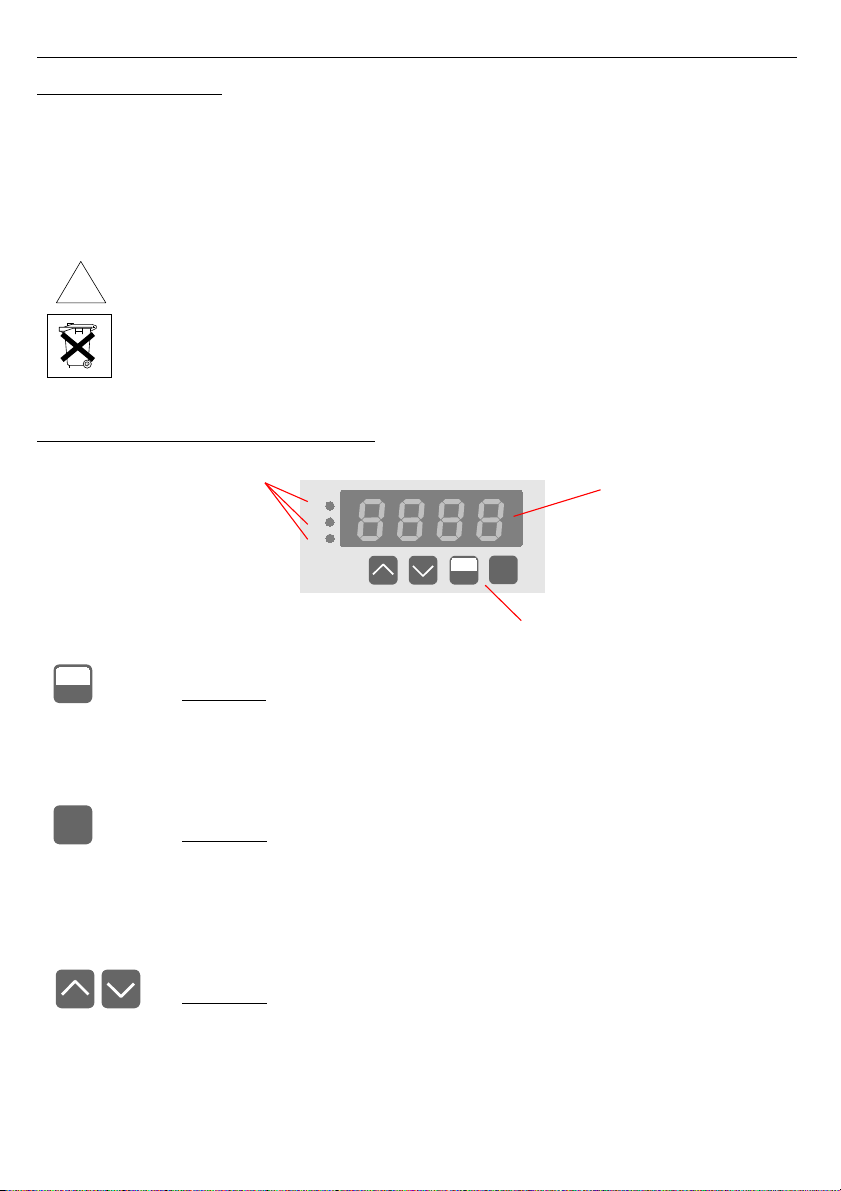
5. FRONT PANEL DESCRIPTION
Symbols and functions of push-buttons:
Symbol used in the manual: [ESC/MENU]
Functions:
• Enter to main menu ( press and hold by at least sec.)
• Exit the current level and Enter to previous menu (or current source
mode),
• Cancel the changes made in parameter being edited
Symbol used in the manual: [ENTER]
Functions :
• switching between displaying of direct current value and recalculated
current value
• Start to edit the parameter
• Enter to the sub-menu,
• Confirmation of changes made in parameter being edited
Symbol used in the manual: [^] [v]
Functions :
• change of output current value,
• Change of the present menu,
• Modification of the parameter value,
• Change of the display mode.
12
MENU
ESC
ENTER
!
MENU
ESC ENTER
AL
R1
R2
d splay
nact ve
programm ng pushbuttons

User manual for regulated current source SZP-73
6. PRINCIPLE OF OPERATION
After turning the power supply on, device ID and software version are showed on the
display, next the controller goes to the current source mode. After power on, output current
can get default value (defined by user) or value equal to generated directly before power off
(see MENU DESCRIPTION, parameters “Init” and “IvAL”).
6.1. CURRENT SOURCE MODE
In this mode chosen output value is presented on the LED display. Pressing the [ENTER]
button switches between displaying and regulation of direct current value and recalculated
value (scaled to user defined range)
6.1.1. Regulation and displaying of direct current value
This mode is signalized by flashing decimal point (in orange colour if device is equipped with
two-colour display) of displayed current value.
There are available values in range: 4mA (displayed as 4.00) up to 0mA (displayed as 0.00).
Buttons [^] and [v] allows changing of present current value. If user presses and holds one of
these buttons current is being changed with increasing speed.
The range of displayed and generated values is “4.00” ÷ “20.00” in this mode.
6.1.2. Regulation and displaying of recalculated value
In this mode displayed value is recalculated to output current value according to
parameters “OUtL” and “OUtH” (see OPIS MENU). Decimal point position can be set to any
decade using parameter “ nt” (see OPIS MENU).
• if displayed value is equal to value of parameter “OUtL” - output current is equal 4 mA
• if displayed value is equal to value of parameter “OUtH” - output current is equal 0 mA
• all values between “OUtL” and “OUtH” are recalculated to output current according to
formula:
Iout=Z−" OUtL"
"OUtH"−"OUtL" ×16 mA4mA
where Z denotes required value.
Buttons [^] and [v] allow to change of current value (recalculated value in this mode). If user
presses and holds one of these buttons current is being changed with increasing speed.
The range of displayed and generated values is “OUtL” ÷ “OUtH” in this mode.
13
i
i

User manual for regulated current source SZP-73
All accessible parameters can be changed by entering the menu (see: DEVICE
PROGRAMMING). Use the local keyboard or the remote controller to do it. (Note: all
parameters can be remote changed via RS-485 interface).
Configuration of the device (via menu or RS 485 interface) do not stops measures.
7. DEVICE PROGRAMMING
The device menu allow user to set all parameters connected to operation of current
output, displaying mode and access settings. The meaning of the particular parameters is
described in paragraph MENU DESCRIPTION.
7.1. PROGRAMMING MENU
To enter main menu (being in the current source mode) operator must to press and hold
at least sec. [ESC/MENU] button.
If the user password is defined (see parameter “Scod“), operator have to enter correct one
before proceeding to menu options . Entering of the passwords is similar to the edition of
numeric parameters (see: PARAMETERS EDITION ), however presently editing digit is showed
only on the display, other digits are replaced by “-” sign.
After entering of last digit of the password first menu position will be displayed (if the password
is correct) or warning ”Err” in other case.
Pay attention when device parameters are being changed. If it is possible, turn off
controlled installation (machine).
Functions of the buttons while sub-menu and parameters choice:
Selection of sub-menu or parameter for editing. Name of selected item (sub-
menu or parameter) is displayed.
Operation of [ENTER] button depend on present menu position:
• if the name of some sub-menu is displayed - enter this sub-menu; name
of the first parameter (or next level sub-menu) is displayed,
• if the name of some parameter is displayed - enter the edition of this
parameter; present value of the parameter is displayed,
[ESC/MENU] button allow user to exit present menu level and goes to upper
level menu (or current source mode).
After about 1 min. since last use of the buttons, device exits the menu mode and
returns to the current source mode (only if no parameters are in editing mode).
14
ENTER
MENU
ESC
i
!
i

User manual for regulated current source SZP-73
7.2. PARAMETERS EDITION
To start edition of any parameter user should select name of desired one using [^] [v]
buttons and then press [ENTER].
7.2.1. Numeric parameters (digit change mode)
Numerical parameters are displayed as decimal numbers. The mode of its new value
entering depends on chosen edit method ( see parameter „Edit”).
In mode “by digit” („Edit”=”dig”) pressing one of the keys [^] or [v] causes change of
current position (flashing digit) or the sign (+/-). Short pressing of the [ENTER] button causes
change of the position (digit).
Press [ENTER] at least seconds to accept the changes, after that question ”SEt?” is
displayed, and user must to confirm (or cancel) the changes. To conform changes (and story it
in EEPROM) press [ENTER] button shortly after ”SEt?” is displayed. To cancel the changes
press [ESC] button shortly after ”SEt?” is displayed. After that device returns to the menu.
7.2.2. Numeric parameters (slide change mode)
In “slide change” mode („Edit”=”Slid”), buttons [^] and [v] has different functions.
To increase edited value press (or press and hold) [^] button only, the increasing
became quickest as long as button [^] is pressed. To slow down the increasing, button [v] can
be used. If [v] is pressed shortly (and button [^] is still pressed), increasing slow down for
a moment only, if [v] is pressed and held while button [^] is still pressed the increasing slow
down and will be kept on lower speed.
To decrease edited value press (or press and hold ) [v] button only. The decreasing
became quickest as long as button [v] is pressed. To slow down the decreasing, button [^]
can be used. If [^] is pressed shortly (and button [v] is still pressed), decreasing slow down for
a moment only, if [^] is pressed and held while button [v] is still pressed the decreasing slow
down and will be kept on lower speed.
Press [ENTER] at least seconds to accept the changes, after that question ”SEt?” is
displayed, and user must to confirm (or cancel) the changes. To conform changes (and story it
in EEPROM) press [ENTER] button shortly after ”SEt?” is displayed. To cancel the changes
press [ESC] button shortly after ”SEt?” is displayed. After that device returns to the menu.
7.2.3. Switch parameters (“LIST” type)
Switch parameters can be described as a sets of values (a lists) out of which only one of
the options available on the list can be selected for the given parameter. Options of switching
parameter are selected using [^], [v] keys.
Short pressing of [ENTER] causes in displaying of the acknowledge question (”SEt?”). If
key [ENTER] is pressed again, the changes are accepted, stored in EEPROM end the edition
process finished. Pressing the key [ESC] after ”SEt?” causes in cancelling of made changes
and returning to menu.
15

User manual for regulated current source SZP-73
Functions of buttons when editing numeric and switching parameters:
While editing numeric parameter:
• change of current (flashing) digit
• slide change of value (acceleration, deceleration, direction change)
While editing switch parameter - selection of switch parameter.
If numerical parameter is being edited, a short press of [ENTER] button
change edited position. A long press of [ENTER] button (at lest sec.)
causes of display a ”SEt?” ask, which allow user to make sure if change of
the parameter value is correct. If switch parameter is being edited, a short
press of [ENTER] button causes of display a ”SEt?” ask. When [ENTER]
button is pressed again (while ”SEt?” is displayed) the new value of the
parameter is stored in EEPROM memory.
Pressing this button operator can cancel the changes done up to now (if they
were not approved by [ENTER] button after the ”SEt?” ask) and come back
to menu
7.3. MENU DESCRIPTION
“- - - -” - password checking. If some password different from „0000” is set, then every
enter to main menu follows the entering of password. If entered password is
correct then first menu position will be displayed else warning ”Err”, and unit
returns to current source mode.
Due to problem with direct displaying of “m” letter, it is exchanged with special sign
“ “. Independently in user manual letter „m” is used to make it more readable
(example: “modE”).
7.3.1. “OUtL” parameter
This parameter defines lower border of recalculated current value, causing generation
4mA of output current. This parameter can be set to any value from range -999 ÷ 9999 (plus
decimal point).
7.3.2. “OUtH” parameter
This parameter defines upper border of recalculated current value, causing generation
0mA of output current. This parameter can be set to any value from range -999 ÷ 9999 (plus
decimal point).
The ”OUtL” value can be greater than ”OutH” value. In such case current output
range is switched upside down. It means that while displayed (recalculated) value
is increased, output current decreases.
7.3.3. “Pnt” parameter
Decimal point position. It can be set to: “ 0”, “ 0.0”, “ 0.00”, “0.000”
Decimal point position is changed by [^], [v] buttons.
16
MENU
ESC
ENTER
i
i

User manual for regulated current source SZP-73
7.3.4. “Init” parameter
This parameter defines current generated after power on. It can be set to the following values
“UdEF” - user defined value equal to “IvAL” parameter
“LASt” - value equal to value of current generated directly before power off
(its value is stored automatically)
7.3.5. “IvAL” parameter
If parameter “Init” is set to “UdEF ”, then parameter “IvAL”defines output current value
after power on. It can be set to any value form range 4.00 – 0.00 mA.
7.3.6. ”bri” parameter
This parameter allows user to set bright of the LED display, bright can be set to
conventional values from 1 to 8.
7.3.7. ”CoL” parameter
This parameter (available only for devices equipped with two-colour display) defines
basic colour of the LED display:
”grEE” - main colour is green,
”rEd” - main colour is red.
7.3.8. ”Scod” parameter
User password (4-digits number). If this parameter is set at value “0000”, user password
is turned off.
If the user do not remember his password, the access to the menu is possible
by the “one-use password”. To get this password please contact with
Marketing Division. “Single use password” can be used only one time, after
that it is destroyed. Entering this password causes in clearing of user
password, it means sets the user password to „0000”.
The “one-use password” can be used ONE TIME ONLY, it is impossible to use it
again! The “one-use password” can be restored by Service Division only.
7.3.9. ”rS” menu
This menu is connected with RS-485 interface, and sets his properties:
”Addr” - this parameter defines the address of the device, accordingly to Modbus protocol.
It can be set in range from 0 to 199. If the value 0 is set then device, responds to
frames with address 55 (FFh).
17
i
User manual for regulated current source SZP-73
”bAud” - this parameter determines RS-485 interface baud rate. It can be set to one of 8
possible values: ”1.2”, ”2.4”, ”4.8”, ”9.6”, ”19.2”, ”38.4”,”57.6”,”115.2”, which
respond to the baud rates of 1 00, 400, 4800, 9600, 19 00, 38400, 57600 and
115 00 bit/s respectively.
”mbAc” - this parameter sets the access to the configuration registers of the device.
Possible values:
”on” - configuration registers can be set via RS-485 interface,
”oFF” - configuration registers can not be set via RS-485 interface.
”rES ” - this parameter defines minimal (additional) delay between the Modbus message
and the answer of the device (received and sent via RS-485 interface). This
additional delay allows the device to work with poor RS-converters which do not
works properly on baud rates higher than 19 00. This parameter can be set to one
of values:
”Std” - answer as quick as possible, no additional delay
” 1 c”
” 2 c”
” 5 c”
”1 c”
”2 c”
- answer delayed of 10, 0, 50, 100 of 00 chars respectively, where
one character time depends on selected baud rate
In the most cases parameter ”rES ” should be set to ”Std” (no additional delay).
Unfortunately for some third party RS-converters ”rES ” should be adjusted
experimentally. Table 7.1 contains most frequently used values.
”bAud” parameter “38.4” “57.6” “115. ”
”rESP” parameter “ 10c” “ 0c” “ 50c”
Tab.7.1. Sett ngs of ”rESP” parameter
7.3.1 . ”Edit” paramet er
This parameter allows to change the edition mode of numerical parameters:
”dig” - the change to “by digit” mode,
”Slid” - slide change mode.
7.3.11. ”dEFS” parameter
This setting allows to restore the factory settings of the device. To get the access to this
option special password is required: „5465”, next the device displays acknowledge question
„SEt?”. Press [ENTER] to acknowledge the restoring of factory settings or [ESC] to cancel.
7.3.12. ”SErv” menu
This menu contains the parameters for authorized service only. To enter this menu
proper service password must be entered. Improper settings can causes of damage of the
device.
18
i

User manual for regulated current source SZP-73
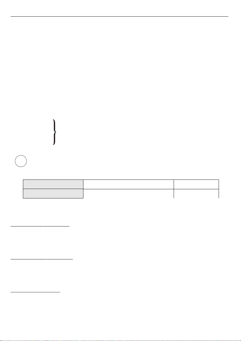
7.4. MENU STRUCTURE
19
0 _ _ _ 4-digit user password entering (if it is different from „0000”)
Press and hold at least 2 seconds
MENU
ESC
ENTER
OUtH
MENU
ESC
MENU
ESC
MENU
ESC
OUtL
Current source mode
MENU
ESC
bri
CoL
ENTER
MENU
ESC
ENTER
Parameter
edition
MENU
ESC
nt
MENU
ESC
Parameter
edition
MENU
ESC
Edit
ENTER
MENU
ESC
MENU
ESC
dEFS
ENTER
MENU
ESC
MENU
ESC
SEt?
4-digit special
password entering
0 _ _ _
ENTER
ENTER
Default settings
restoring
MENU
ESC
SErv
MENU
ESC
IvAL
MENU
ESC
Init
ENTER
MENU
ESC
ENTER
Parameter
edition
mbAC
rES
ENTER
MENU
ESC
ENTER
ENTER
MENU
ESC
Addr
bAud
Parameter
edition
rS
MENU
ESC
Scod
MENU
ESC

User manual for regulated current source SZP-73
8. THE MODBUS PRO TOCOL HANDLING
Transmission parameters: 1 start bit, 8 data bits, 1 or stop bit ( bits are send, 1 and bits
are accepted when receive), no parity control
Baud rate: selectable from: 1 00 to 115 00 bits/second
Transmission protocol: MODBUS RTU compatible
The device parameters and display value are available via RS-485 interface, as HOLDING-
type registers (numeric values are given in U code) of Modbus RTU protocol. The registers
(or groups of the registers) can be read by 03h function, and wrote by 06h (single registers) or
10h (group of the registers) accordingly to Modbus RTU specification. Maximum group size for
03h and 10h functions can not exceeds 16 registers (for single frame).
The device interprets the broadcast messages, but then do not sends the answers.
8.1. LIST OF REGISTERS
Register Write Range Register description
01h1Yes 400 ÷ 000 Generated current value (diect value) expressed in 0,01 mA
0 h1Yes -999 ÷ 9999 Rescaled current value expressed according to “OUtL”and “OUtH”
06h Yes -999 ÷ 9999 “OUtL” parameter, no decimal point included
07h Yes -999 ÷ 9999 “OUtH” parameter, no decimal point included
08h Yes 0 ÷ 3 “nt ” parameter: 0 - “ 0”; 1 - “ 0.0”; 2 - “ 0.00”; 3 - “0.000”
09h Yes 0 ÷ 1 “Init” parameter: 0 - UdEF option; 1 - LASt option
0Ah Yes 400 ÷ 000 “IvAL” parameter, expressed in 0,01 mA
0h Yes 0 ÷ 199 Device address
1h No 065h Device identification code (ID)
h3Yes 0 ÷ 7
“bAud” parameter in “rS” menu (baud rate);
0 - 1 00 baud; 1 - 400 baud; 2 - 4800 baud; 3 - 9600 baud;
4 - 19 00 baud; 5 - 38400 baud; 6 - 57600 baud; 7 - 115 00 baud
3h4Yes 0 ÷ 1 “mbAc” parameter in “rS” menu (permission to write registers via
RS-485 interface); 0 - write denied ; 1 - write allowed
5h Yes 0 ÷ 5
“rES ” parameter in “rS” menu (additional response delay);
0 - no additional delay; 1 - ”10c” option; 2 - ”20c” option;
3 - ”50c” option; 4 - ”100c” option; 5 - ”200c” option;
Dh Yes 1 ÷ 8 “bri” parameter (display brightness);
1 - the lowest brightness; 8 - the highest brightness
Eh Yes 0 ÷ 1 “CoL” parameter (main colour of display): 0 - green; 1 - red
Fh Yes 0 ÷ 1 “Edit” parameter (numerical parameters edit mode);
0 - „dig” mode; 1 - „SLid” mode
20
i
This manual suits for next models
1
Table of contents
Other Simex Controllers manuals


Popular Controllers manuals by other brands

LIXiSE
LIXiSE LXC701 Series user manual

heat-timer
heat-timer DIGI-SPAN VSP Elite Installation and operation instructions

Sony
Sony HomeShare RMN-U1 instruction & operation manual

BP Hobbies
BP Hobbies Cheetah 60A quick start guide

Go Fermentor
Go Fermentor NET operating manual

Ltech
Ltech WiFi-102-CT operating instructions


