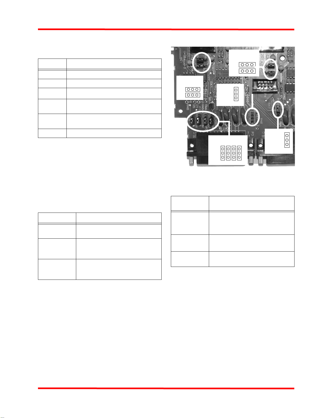
Simplex 4100-6062 Technical specifications

© 2004. 2011 SimplexGrinnell LP. All rights reserved.
Specifications and other information shown were current as of publication and are subject to change without notice. Tyco Safety Products,
Simplex and the Simplex logo AUTOCALL, TFXnet, and CONSYS are trademarksare trademarks of Tyco International Ltd. and its affiliates
and are used under license.
4100-6062 TFXi Installation
and Programming Instructions
Overview
The 4100-6062 TFX Interface (hereafter referred to as the TFXi)
provides the following functionality:
• It allows a 4100U or a 4100ES Fire Alarm Control Panel
(FACP) to transmit specific events (Fire, Trouble, Supervi-
sory, Signal Silence, System Reset, Control, Utility, etc.)
over the TFXnet to TFX fire panels and annunciators.
• It monitors the state of specific TFX points, and turns on the
FACP pseudo points when the state of the TFX point
changes. These pseudo points can be associated with spe-
cific system actions (for example perform a system reset on
the FACP), or they can be utility pseudo points linked to
Custom Control equations that perform facility-specific
actions (for example, turn on relays).
The TFXi consists of a 2” x 11.5” motherboard, which mounts to
the chassis of an FACP, and a daughter card, containing an RS-
232 connector and TFXi firmware, that mounts in a socket on the
motherboard.
Battery current requirements for the 4100-6062 TFX Interface
Module are as follows:
• Supervisory Current = 132 mA
• Alarm Current = 132 mA
In this Document
Related Documentation - - - - - - - - - - - - - - - - - - - - - - - - - - - - - 2
Replacing 4100U/4100ES Single Page Operating Instructions- - 2
Setting Jumpers and Switches - - - - - - - - - - - - - - - - - - - - - - - - 2
Installing TFXi Card in an FACP Bay - - - - - - - - - - - - - - - - - - - - 3
Wiring TFXi to TLT-530 - - - - - - - - - - - - - - - - - - - - - - - - - - - - - 5
TLT-530 Configuration - - - - - - - - - - - - - - - - - - - - - - - - - - - - - - 5
IDC Monitoring Operation- - - - - - - - - - - - - - - - - - - - - - - - - - - - 8
Adding TFXi Card to Job - - - - - - - - - - - - - - - - - - - - - - - - - - - - 8
Network Option Tab Settings- - - - - - - - - - - - - - - - - - - - - - - - - - 8
Subnet Tab Settings- - - - - - - - - - - - - - - - - - - - - - - - - - - - - - - - 8
Zones Tab Settings - - - - - - - - - - - - - - - - - - - - - - - - - - - - - - - - 9
Points Tab Settings - - - - - - - - - - - - - - - - - - - - - - - - - - - - - - - - 9
Application Programming Overview- - - - - - - - - - - - - - - - - - - - 10
Programming Peer-to-Peer Operation - - - - - - - - - - - - - - - - - - 11
Programming TFX Master-to-4100U/4100ES Slave Operation- 14
Programming 4100U/4100ES Master-to-TFX Slave Operation- 15
Appendix A. Example Programming Screen- - - - - - - - - - - - - - 16
Appendix B. TFX Predefined System Points- - - - - - - - - - - - - - 17
Appendix C. 4100U/4100ES Card Status Troubles - - - - - - - - - 18
),5($/$50&21752/
!#+./7,%$'%
4&8NET
4&8:/.%3-/+%
&)2%!,!2-
4,) 4,4
23
4&8 5
&!#0&,23-+&)2%
3-/+%$%4%#4/2
:/.%
3-/+%
-
3-/+%
-
Figure 1 TFXi Functional Overview (4100U Shown)
579-575
Rev. E
firealarmresources.com

2
4100-6062 TFXi Installation and Programming Instructions
Related Documentation
Replacing 4100U/4100ES Single
Page Operating Instructions
Adding the TFXi to the FACP changes the way in which opera-
tors interact with the FACP panel. Replace the single page oper-
ating instruction shipped with the FACP with the appropriate
TFX Interface instruction listed below.
Setting Jumpers and Switches
Setting Jumpers.
Figure 2 shows the locations of the
jumpers on the TFXi card, and identifies the number
assigned to each jumper pin. The specific jumper settings
required on the TFXi card are listed in Table 3.
Figure 2 Jumper Settings
Setting Baud/Address Switch (SW1). Switch SW1 on the
TFXi card is a bank of eight dip switches. From left to right (see
Figure 3 below) these switches are designated as SW1-1 through
SW1-8. The function of these switches is as follows:
• SW1-1. This switch sets the baud rate for the internal 4100
communications line running between the card and the 4100
CPU. Set this switch to ON.
• SW1-2 through SW1-8. These switches set the card's
address within the FACP. Refer to “Appendix D. Card
Address Settings” at the end of this document for a list of
the switch settings for all of the possible card addresses.
Note: You must set SW1-2 through SW1-8 to the
value assigned to the card by the FACP Pro-
grammer. SW1-8 is the LSB.
Table 1: Related Documentation
Part # Description
574-848 Simplex
®
4100ES Installation Manual
19700344 TLT-530 Network Interface Guide
574-849 Simplex ES Panel Programmer’s Manual
19700457 TNI562/TNI-563 Network Interface
Installation Guide
850463 AUTOCALL
®
TFX-500/800 CONSYS
®
Programming Guide
850520 TFXnet Network Programming Guide
Table 2: Replacement Operating
Instruction Part Numbers
Original Part # Replacement Part #
574-852 579-701 TFX Operating
Instructions
579-352 579-700 TFX Operating Instructions
for Firefighter’s Audio System (Digital
Audio, 3-8 Channels)
579-305 579-702 TFX Operating Instructions
for Firefighter’s Audio System (Single
and Dual Channel Audio)
Table 3: Required Jumper Settings
Jumper Setting
P1, P7, P8,
P9, P10
Place jumper on pins 1 and 2
Do not change the setting for P1
(256)
P5, P6, P11,
P12, P14 Place Jumper on Pins 2 and 3
P13 Place Jumper only on Pin 1
P8
P10
P7
P9
13 2
Jumper
Pin #s
P13
1
3
2
Jumper
Pin #s
Jumper
Pin #s
321
P5P6
Jumper
Pin #s
321
P11P12
P14
13 2
Jumper
Pin #s
firealarmresources.com

3
4100-6062 TFXi Installation and Programming Instructions
Figure 3 Internal Baud/Address Dipswitch
Installing TFXi Card in an FACP Bay
Installation guidelines differ slightly, depending on whether the
TFXi is being installed in a CPU or expansion bay.
Parts List
CPU Bay Installation Guidelines
• Up to two 2 x 11.5” motherboards, such as the one used
with the TFXi card, can be installed in a CPU bay. If possi-
ble, install the TFX’s 2 x 11.5” motherboard in a CPU bay
slot.
• The CPU motherboard must be installed in the position
shown in Figure 4.
• The power supply must be installed in the right side of the
bay.
Figure 4 Typical CPU Bay Installation
Expansion Bay Guidelines
• Up to seven 2" x 11.5” motherboards can be installed in an
expansion bay if no 4" x 5" modules are installed in the bay.
Motherboards are mounted on top of the PDI in expansion
bays. The data and power that would normally be bussed via
the PDI is instead routed across the boards via the J1 con-
nector and P1 header pins.
• As shown in Figure 5 below, motherboards can also be
installed alongside 4" x 5" cards, if necessary.
• The leftmost slot must not contain a motherboard.
• 2” x 11.5” Motherboards must be added from left to right.
• A 733-525 harness is used to pass power and communica-
tion from the bay above to the expansion bay.
Figure 5 Typical Expansion Bay Installation
Installing TFXi Motherboard
1. Orient the motherboard with the connector labeled J1 on the
right and the header labeled P1 on the left.
2. Match the connector on the previously installed mother-
board with the pins on the 2 x 11.5” motherboard you are
installing. For an expansion bay, install motherboards from
Qty Description Part
#
1 TFX Network Interface Board 566-587
1 4100 Mother Board 562-799
4 Screw 426-047
8 Washer 268-009
4 Standoff 202-090
2 Spacer 202-091
1 Harness 734-165
1
8
7
6
5
4
3
2
OFF
ON
Set SW1-1
to ON
Figure shows an example
address of 3. Refer to Appen-
dix D for a list of address set-
tings.
4100 Option Bd
4100 Option Bd
Slot 1 Slot 2 Slot 3 Slot 4
IDNet
Aux
Pwr Aux
Relays
Btry
+
-
Chassis
NACs 1,2 & 3
System Power Supply
(SPS)
Slot 5 Slot 6 Slot 7 Slot 8
Network Bd
Master Controller Bd
Network Media Bds
service Modem
4100-6030
Alarm
Relay
4100-6033
SPS Mezzanine
Cards
City Circuit
4100-6031
4100-6032
CPU Motherboard
No Boards
Allowed
in
This Slot
PDI
4x5 Module
Expansion Power
Supply
(XPS)
4x5 Module
I/O Wiring
I/O Wiring
I/O Wiring
4100 Option
4100 Option
4100 Option
Slot 1 Slot 2 Slot 3 Slot 4 Position
5
Position
6
Position
7 & 8
firealarmresources.com

4
4100-6062 TFXi Installation and Programming Instructions
left to right. Slide the motherboard to the left until the pins
are completely inserted in the connector. For a CPU bay,
install motherboards from right to left. Slide motherboard to
the right until pins are completely inserted in connector.
Figure 6 Connecting 2” x 11.5” Motherboards
Securing Motherboard to Chassis
Secure the motherboard to the chassis using washers, standoffs,
and four Torx screws.
Figure 7 Securing 2” x 11.5” Motherboard to Chassis
Connecting 733-525 Power and Comm Harness
Connect a 733-525 power and communication harness to the
TFXi motherboard only if it is the leftmost board installed in an
expansion chassis. As shown in Figure 8, the harness connects
the leftmost 2” x 11.5” card in an expansion chassis to the left-
most 2” x 11.5” card in the bay above the TFXi motherboard.
If the TFXi motherboard is installed in the CPU bay or in any
other expansion bay slot, it receives its power and communica-
tion from the bus created when adjacent motherboards are joined
by the J1 and P1 connectors, and no harness is necessary.
Figure 8 733-525 Harness
Installing TFXi Daughter Card
The TFXi daughter card inserts into the connector located in the
center of the motherboard. The connector is keyed so that the
daughter card fits only one way. Before installing the card,
examine the slot in the motherboard and the fingers on the
daughter card and note where the key is located.
P1
J1
733-525
Harness
Connector
with blue
wire to P2
Connector
with white
wire to P3
Connector
with blue
wire to P2
Connector
with white
wire to P3
TFXi
CPU
Bay
Expansion
Bay
firealarmresources.com

5
4100-6062 TFXi Installation and Programming Instructions
Wiring TFXi to TLT-530
Use harness 734-165 to connect the TFXi to the TLT-530 net-
work interface module. Connect the end of the harness contain-
ing the DB-25 connector to Port A on the TFXi daughter card.
Connect the end of the harness with the RJ-11 connector to PL2
on the TLT-530.
The length of the harness is 14 feet. It must be installed in con-
duit (max. length 6 feet) run between the FACP and the TLT-530
Figure 9 Interconnecting TLT-530 and TFXi
Pinouts for the 734-165 harness connectors are as follows:
Figure 10 RJ-11/DB-25 Pinouts
TLT-530 Configuration
Wiring for the TLT-530 and the RPS-424 Power Supply/Battery
Charger is shown in Figure 11. Substitute this illustration for
the one found in 19700344-5a.
Switch settings are listed in the Tables 4 through 11.
4100 motherboard
Assy:562-799
socket
4100 TFX network
Interface Board
Assy: 566-587
PID: 4100-6062
plug
3-Rcv
4-Cts
5-Gnd.
1-Xmit
2-Rts
Port 2
7
6
8
6-Rcv
5-Cts
4-Gnd.
8-Xmit
7-Rts
Port 1
2
3
1
4100
Harness 734-165
Port B
Port A
RS232
or
2120
TNI-563 Network Interface
TNI-530 provides supervised
commmunications interface between the
TFXnet fire control network and UL1950 or
UL864 listed third party equipment.
TLT-530
Board
PL2
TNI-563
RJ11
See Figure
10
No
Connection
to Port B
Table 4: LED Designations
LED Function
DS1 Green Processor run (Normally On
DS2 Yellow Network Ground Fault (Normally Off)
DS3 Red Network Port L Transmit (On when transmitting)
DS4 Red Network Port L Receive (On when receiving)
DS5 Red Network Port R Receive (On when receiving)
DS6 Red Network Port R Transmit (On when transmitting)
RCV In - 2
XMIT Out - 3
RTS In - 4
Sig.Gnd. - 1 red
orange
grn
blu
CTS Out - 5
blk
wht
Not Used - 6
RJ-11
XMIT Out - 2
RCV In - 3
RTS - 4
Sig.Gnd. - 7
DB25 male
red
orange
grn
blu
CTS - 5
blk & shield
wht
No Connection
DB-25
firealarmresources.com

6
4100-6062 TFXi Installation and Programming Instructions
Note: Set Switch SW1 on the TLT-530 for third party operation
as shown above. Do not use the third-party switch settings listed
in Table 5 of 19700344-5a.
These are switch SW2 designations for the TLI-530 and TLT-530
modules. Note: OFF = Value (1=Off, 0=ON)
Table 5: LK Header Configuration
Header Link A Link B
1Network disconnected; data
sent to TB2-1-4. Normal Operation
2 Not used Normal Operation
3 Not used Normal Operation
4 Not used Normal Operation
5 Not used Normal Operation
Table 6: SW1 Network Baud Rate Switch Settings
Network
Baud Rate Switch Position
SW1-4 SW1-5 SW1-6
1200 ON ON ON
2400 OFF ON ON
9600 ON OFF ON
19200 OFF OFF ON
38400 ON ON OFF
Reserved OFF ON OFF
Reserved ON OFF OFF
Reserved OFF OFF OFF
Table 7: TLT-530 SW1 Switch Settings for Third Party
Interface
ThirdParty
Interface
SW1-1 SW1-2 SW1-3
ON OFF ON
Table 8: SW1 Network Topology Switch Settings
Network
Topology Switch Position
SW1-7 SW1-8
Bus ON ON
Star ON OFF
Ring OFF ON
Redundant
Star OFF OFF
Table 9: SW2 Switch Settings
SW2 Switch Value (OFF)
11
22
34
48
516
632
764
* SW-1 through SW-7 are binary address values (values with
switch Off).
Table 10: Switch SW2-8 Setting
SW2-8 Position Function
OFF RS-232 Port (PL2)
Table 11: Switch SW3 Settings for the TLT-530 Modules
Switch Function
SW3 Momentary switch; Push to
reset the board processor.
firealarmresources.com

7
4100-6062 TFXi Installation and Programming Instructions
Figure 11 TLT-530 and RPS-424 Wiring
"4
"4
73%#.%,)3
4 %#.%,)3
4 4
$##
4
$##
$##
$##
3
"4
"4
,0
,0
"4
203
0/7%23500,9
"!44%29#(!2'%2
0.
,,./.0/,!2):%$
6!#
(:!54/3%,%#4
5,
,)34%$503
!#).054&2/-503
./.0/7%2,)-)4%$
350%26)3%$
,
,
,/#!,!#7)2%
4/3!-%3/52#%
!35
"4
"4 "4
*
4/&!5,4/54054
/&4,)4,4
#!").%4'2/5.$
4/%!24('2/5.$
234/5
#!",%0.
&4
350%26)3%$
0/7%2,)-)4%$
#,!33
350%26)3%$
0/7%2,)-)4%$
#,!33
"%352%4(!44(%4,437)4#()33%44//&&3/
4(!423#/--5.)#!4)/.)3%.!",%$
./4%
#!",%0.
*$##
*6$#
*6$#
$##
6
&!5,4/54
$##
6
6
4.!
0.
4,4
0.
4
4
6
./2-!,,9#,/3%$.#
#/.4!#43/&4(%503-!).3
350%26)3/292%,!9/54054
3(/244/'%4(%2)&./4&53%$
6$#3500,)%$
"9203
3(/244/'%4(%2
)&./4&53%$
4/203
0/7%23500,9
"!44%29#(!2'
2%&%24/4"
4%2-).!,
$%3)'.!4)/.3
7)2%4/
4&8./$%3
0/7%2
,)-)4%$
7%7HUPLQDO'HVLJQDWLRQV
7HUPLQDO )XQFWLRQ
7% 561HW3RUW/
7% 561HW3RUW/
7% 6KLHOG
7% 561HW3RUW5
7% 561HW3RUW5
firealarmresources.com

8
4100-6062 TFXi Installation and Programming Instructions
IDC Monitoring Operation
The IDC is used to monitor normally open contacts of the PSM
(976123). The contact will open if the RPS-424 indicates an AC
loss, ground fault, battery low or battery missing. The correct
EOLR is placed across the Com and NC contacts (relay is nor-
mally energized). The IDC must be mounted in the same room
and the wiring is to be in conduit.
Adding TFXi Card to Job
1. Start the FACP programmer, open the job corresponding to
the panel into which the TFXi card has been installed.
2. Click on the Hardware tab.
3. In the Available Hardware list, click on Interface to expand
the list of available interface cards and locate the TFX Inter-
face entry.
4. Drag the entry for the TFXi over to the appropriate Unit/
Box/Bay.
5. Double click on the TFXi card icon to open its program-
ming properties screen. The properties screen contains five
tabs across the top. Refer to the sections below for informa-
tion on specifying information in these tabs.
6. Click on the programmer’s Panel tab. At the bottom of the
Panel tab, click on the System Options subtab. Check the
box labeled “Combined Alarm and Hardware Reset.”
Network Option Tab Settings
The network option tab allows you to specify settings for the
TFXi card’s network parameters, identify the node numbers for
up to three Designated Receiving Units (DRUs), and select
whether the FACP receives TFX network fault indications. Use
these guidelines to select values for these choices.
•Network Options. Set the Node Number parameter to a
unique value. This is the node number used by the TFXi
card. Refer to the TFXnet documentation (publications
19700344 and 850520, and TIB 504) for information on set-
ting all other network parameters.
•Designated Receiving Units (DRUs). A DRU is a
device on the TFXnet that has been designated to receive
TFXnet events and messages for display and/or acknowl-
edgement. Use the three fields, designated DRU1, DRU2,
and DRU3, to identify the node numbers of the TFXnet
DRUs.
•Fault Mask. Each of the Fault Mask check boxes corre-
sponds to a TFXi Card Status Point on the FACP. Checking
a box indicates that if the TFX fault occurs, the correspond-
ing TFXi Card Status Point generates a trouble on the FACP.
(You can view the Card Status Points by selecting the Points
tab in the FACP programmer and scrolling to the address
that corresponds to the TFXi card. The Card Status Points
for the TFX faults are points 2-7 on the TFXi card.)
Note: Do not change default settings unless directed to by Tech-
nical Support. Refer to TIB 504 for additional information.
Figure 12 Network Option Tab
Subnet Tab Settings
The subnet tab allows you to specify which TFX nodes are mon-
itored by the TFXi card. Events from a node can be monitored by
the TFXi when the node’s entry in the list reads Member. To
select all nodes, click on the Set All button. To toggle whether an
individual node is selected, click on the node and press the space
bar.
firealarmresources.com

9
4100-6062 TFXi Installation and Programming Instructions
Figure 13 Subnet Tab
Zones Tab Settings
The Zones Tab allows you to specify the zone links and sectors
corresponding to the zones used by the TFXnet and FACP.
Zones, zone links, and sectors are logical groupings of TFXnet
points.
Understanding the role of zone links is especially important
when connecting a TFX panel to an FACP. Network zone links
provide a method for linking (or equating) a zone and/or zones
together in different panels. For example, if zone 80 in panel 1 is
a network zone linked to zone 01 in panel 2, then panel 2 pro-
cesses events received from panel 1, zone 80 as if they originated
in zone 01 of panel 2.
You do not need to specify every zone and sector used on the
TFXnet, but you do need to specify the following:
• Existing TFXnet zones/sectors with which FACP points will
be associated.
• Any zones that will be used for 4100U/4100ES points only.
To specify a zone, click on the zone number in the list at the top
of the screen. Next, click on the Sector drop down list box and
choose a sector number. Click on the Zone Link drop down list
box and choose a zone link.
Either a zone link or sector assignment, or both, can be used.
Refer to TFXnet Programming Guide 850520 for additional
information.
Figure 14 Zones Tab
Points Tab Settings
The following sections provide general descriptions of the Points
Tab fields. Specific application examples are described in the
remainder of this manual.
General Steps for Programming TFX Events to Activate
4100U/4100ES Actions
1. Define a digital user pseudo point, assigning it either a
Fire, Trouble, Pri2, Supv, or utility point type. This is
the FACP point that will turn on when the correspond-
ing TFX Zone and point turns on.
2. In the properties area of the Points Tab, do the follow-
ing:
a. Set the Scope to EXT (external).
Figure 15 Points Properties
b. Move the cursor to the FACP Point field and press F9.
A taglist appears. Locate the digital pseudo point
defined in Step 1 and press the space bar. Two >> char-
acters appear to indicate the point is selected. Click OK
in the taglist to return to the Points Tab.
firealarmresources.com

10
4100-6062 TFXi Installation and Programming Instructions
c. For a non-trouble event, choose Active; otherwise
select Trouble.
d. Click on the Group drop down list box and select the
group for the zone (from your CONSYS job).
3. On the FACP, program the action that should occur when
the pseudo point activates (turns on). Options include:
-Start Custom Control. The pseudo point can be
used as a switch for starting a custom control equation.
This equation might, for example, turn on notification
appliances, illuminate an LED on an annunciator, or
activate a bell at a guard station.
-GCC/NPU Network Programming. Use the net-
work programmer to define the pseudo point as a pub-
lic point on the FACP and as an external point on the
GCC/NPU. When the pseudo turns on, its Fire or Trou-
ble status is annunciated at the GCC/NPU.
-No Additional Programming. If you perform no
additional programming, the following occurs. When
the pseudo point turns on, the panel piezo activates and
the Fire or Trouble condition appears on the LCD dis-
play with the pseudo point’s descriptive label.
General Steps for Programming 4100U/4100ES Events
to Trigger TFX Actions
1. In the properties area of the Points Tab (see Figure
15), set the Scope to PUB (public).
2.
Move the cursor to the FACP Point field and press F9. A
taglist appears. Press the space key to s
elect the FACP
point to be monitored. Typically, this is either an initi-
ating device (such as a smoke detector) or a system
list (such as L18, general fire alarm monitor zones).
3. Click on the FACP Event Type field and select an
event type. This is the FACP point state that must be
true to cause the TFX event (selected in the next step)
to be sent to the TFXnet.
4. Select the TFX event to be sent when the condition
selected in Step 3 is true, as follows:
- Click on the TFX Event State drop-down list box and
choose an TFX event condition, if the FACP Event you
selected in Step 3 was a Fire, Supervisory, Control, or
Utility event.
- Click on the Trouble Event State drop-down list box
and choose a TFX trouble condition, if the FACP event
you selected in Step 3 was a Trouble event.
5. Click the Zone Number list box and select the zone
number to which the TFX event selected in Step 4
will be sent.
6. Enter the appropriate value to be logged for this event.
7. Select the Zone Number for this point.
8. Click on the Group drop down list box and select the
group number to which the TFX event selected in
Step 4 will be sent.
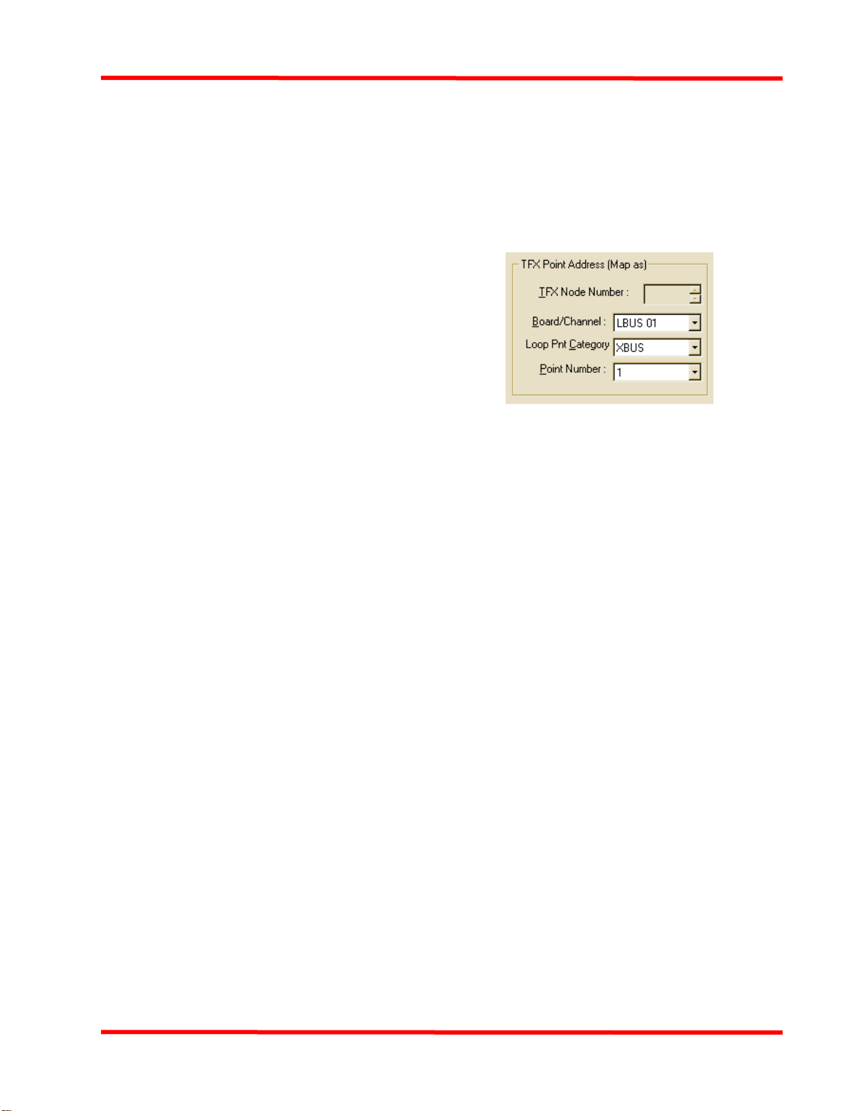
9. Choose the point on the TFXnet to activate when the
FACP point state (chosen in Step 3) is true. Specify
the point’s channel, point category, and point number,
using the fields shown in the figure below.
Figure 16 TFX Point Properties
Downloading and Testing
Use the FACP programmer to download the edited job to the
panel containing the TFXi. Make sure to test the functionality of
the TFXi in both directions.
Application Programming Over-
view
The FACP with a TFXi card supports three distinct operating
modes on a TFX network, as follows:
•Peer-to-Peer. The FACP and TFX panels control each
other in a peer-to-peer relationship, meaning each panel on
the network subnet is capable of performing a signal
silence, system reset, or acknowledge operation on the other
panels.
•TFX Master to FACP Slave. All control operations --
such as Acknowledge, Signal Silence, and System Reset --
are performed ONLY at the master node (TFX) and are not
allowed at a slave node (4100U/4100ES).
•4100U/4100ES Master-to-TFX Slave. All control oper-
ations -- such as Acknowledge, Signal Silence, and System
Reset -- are performed ONLY at the master node (4100U/
4100ES) and are not allowed at a slave node (TFX).
The operating mode in use on the subnet is determined by the
type of programming you choose to implement. The following
sections describe the various programming options.
Important Note: To match the operation of a TFX panel, the
programmer modifies the default FACP operation when a TFXi
card is added to the job. The modification changes the front panel
operation so that a Signal Silence MUST be performed BEFORE
firealarmresources.com

11
4100-6062 TFXi Installation and Programming Instructions
a System Reset. If a System Reset is attempted without first per-
forming a Signal Silence, the reset is not performed. This auto-
matic change applies to all three of the network modes described
above.
Programming Peer-to-Peer
Operation
Receiving Points from the TFX Network
To cause a fire, trouble, or supervisory at the FACP panel, do the
following:
1. Select EXT as the scope.
2. Add a UTIL user pseudo (P512 in this example).
3. Add a FIRE user pseudo (P519 in this example).
• To cause a Supervisory in the FACP, substitute a
SUPV user pseudo.
• To cause a Trouble in the FACP, substitute a TROU-
BLE user pseudo.
• To cause a Utility in the FACP, substitute a UTIL use
pseudo.
4. Write two SMPL equations (replace P512 and P519 with
your values).
Example:
[INPUTS]
STATUS ON
P512 | DIGITAL | UTILITY | TFX NODE 3 DEV 1 - PULL
[END INPUTS]
[OUTPUTS]
HOLD ON PRI=9,9
P519 | DIGITAL | FIRE | FIRE: TFX NODE 3 DEV 1 - PULL
[END OUTPUTS]
[INPUTS]
STATUS ON
A20 | ANALOG | TIMER | FIRE ALARM CLEAR PULSE
TIMER
AND NOT STATUS ON
P512 | DIGITAL | UTILITY | TFX NODE 3 DEV 1 - PULL
[END INPUTS]
[OUTPUTS]
HOLD OFF PRI=9,9
P519 | DIGITAL | FIRE | FIRE: TFX NODE 3 DEV 1 PULL
[END OUTPUTS]
Enter other information as follows:
• For TFX Event State, for a non-Trouble event, select
Active; otherwise, select Trouble.
• For Group, enter the TFX Group Number from the CON-
SYS job or report for the TFX panel.
• For TFX Node, enter the TFX panel node number which
contains the device/point.
• For TFX Board/Channel, enter the TFX Channel of the
device/point, as follows:
- For a TFX-400/500 addressable loop point, enter MP.
- For a TFX-800 panel addressable loop point, these are
identified as Local Buses LBUS 11-15 with two loops
each:
Loops A and B, use LB 11
Loops C and D, use LB 12
Loops E and F, use LB 13
Loops G and H, use LB 14
Loops J and K, use LB 15
- Any other TFX-800 point (ex. Main CPU board point),
use MP.
• For Point Category (A.K.A. Loop):
- For an addressable TFX-400/500/800 loop point:
First loop, (A, C, E, G, J) enter FIRST 60
Second loop (B, D, F, H, K) enter SECOND 124
- For a non-addressable loop point (see also Appendix
A, TFX Predefined System Points), use these values:
Expansion Bus point (Category X) non-loop point
type, use XBUS 128
Real (Category R) non-loop point type, use REAL
Pseudo (Category P) non-loop point type, use
PSEUDO
Keyboard (Category S) non-loop point type, use
SWITCH
User Logon Number non-loop point type, use USER
• For Point Number:
- Addressable loop device, enter the TFX device address
- Non-addressable loop point, use the value from
Appendix A - TFX Predefined System Points
IMPORTANT: Values for the following set of fields must be set
in accordance with CONSYS programming conventions.
Unsuitable or invalid values may result in no operation or unin-
tended operation at the TFX nodes on the network.
Sending Points to the TFX Network
To send a point to the TFX Network (from the FACP), do the fol-
lowing:
1. For Scope, select PUB.
2. For Point, enter the FACP point (ex. M1-2, P536, etc.) to
send
3. For FACP Event Type, enter the appropriate event (Fire,
Pri2, Supv, Trbl, Control, or Util)
firealarmresources.com

12
4100-6062 TFXi Installation and Programming Instructions
• TFX Event State
- For a Trouble event, select the appropriate trouble (ex.
78 for a Battery Fault. Note: You MUST also enter the
same Trouble event number in the Trouble Event State.
For a non Trouble event (ex. Fire, Switch input), select
151 - Input Active (not logged).
• Trouble Event State
- For a point which has a Trouble state in addition to,
and different from, the TFX Event State, select the
appropriate trouble (ex. 54 Device Fault for a Trouble
on an IDNet Fire device)
- For a Trouble only point, enter the same value which
was entered in TFX Event State above
• For Logging Event, enter the appropriate value to be logged
for this event. This allows an event to be displayed and
entered into the history log and printed at TFX nodes if
required.
• For Zone Number, enter the Zone in which the point resides
from your CONSYS planning forms.
• On the Zones tab, enter the Sector and Zone Link in which
the zone resides.
• For Group Number, enter the appropriate Group (see
Appendix B of the Autocall TFX CONSYS Programming
Manual, Appendix B)
• For TFX Board/Channel:
- For an IDNet device 1-127:
1st and 2nd IDNet channel devices 1-127, use LBUS
11
3rd and 4th IDNet channel devices 1-127, use LBUS
12
5th and 6th IDNet channel devices 1-127 use LBUS 13
7th and 8th IDNet channel devices 1-127, use LBUS 14
9th and 10th IDNet channel devices 1-127, use LBUS
15
- For an IDNet device 128-250, substitute RBUS 11-15
for LBUS 11-15, respectively
- For any other point, enter LBUS 1-10, RBUS 1-10
• For TFX Loop Point Category:
- IDNet channel point:
IDNet Channel 1, 3, 5, 7, 9 enter FIRST
IDNet Channel 2, 4, 6, 8, 10 enter SECOND
- Any other point, select XBUS
• For TFX Point Number:
- For an IDNet channel enter the device address - enter
address (if greater than 127, subtract 127)
- For a non-addressable point enter the Point value in the
FACP C-P-S (Card-Point-Subpoint) triplet. If the
Point is 0 (such as a card status), use the Subpoint
value and add 30 (ex. for card status x-0-0, use 30, for
card status x-0-15, use 45). Please consult the Points
tab in the FACP Programmer or a generated report for
this information.
Application 1: Activating All 4100U/4100ES Signal Cir-
cuits following a TFX Fire Alarm
The following FACP Custom Control example activates all of the
FACP’s notification appliances (audibles are in List L8 and visu-
als are in List L9) if the state of Fire pseudo P519, which is
linked to TFX Node3, device 1, turns ON.
[INPUTS]
STATUS ON
P519 | DIGITAL | FIRE | FIRE: TFX NODE 3 DEVICE 1 - PULL
STATION
[END INPUTS]
[OUTPUTS]
HOLD ON PRI=9,9
L8 | LIST | CONTROL | FIRE ALARM SIGNALS OFF ON
SILENCE
HOLD ON PRI=9,9
L9 | LIST | EMPTY | FIRE ALARM SIGNALS OFF ON
RESET
[END OUTPUTS]
Application 2: Using 4100U/4100ES Signal Silence or
System Reset Keys to Silence or Reset TFXnet Devices
This programming example links two FACP digital pseudo
points (P6 - Alarm Silence and P0 - System Reset) to a pair of
fixed TFXnet/CONSYS points that control signal silence and
system reset on the TFX network.
Pressing Signal Silence or System Reset on the FACP turns the
FACP pseudo point ON, which in turn activates the correspond-
ing TFXnet point and performs the silence or reset operation on
the TFXnet.
To program this application, edit the Points tab with the values
listed in the following table.
Table 12: Points Tab Settings,
FACP to TFX Signal Silence/System Reset
Parameter Setting
Scope Set the Scope to Public for both Appli-
cations.
FACP Point Use P6 for Alarm Silence operation;
P0 for Detector/System Reset.
FACP Event
Type Set to UTIL for both applications.
firealarmresources.com

13
4100-6062 TFXi Installation and Programming Instructions
Application 3: Programming 4100U/4100ES ACK Keys
to Silence TFX Piezo
This programming example allows the FACP ACK keys (Fire
ACK, Trouble ACK, Supervisory ACK) to silence the local piezo
on a TFX panel when it activates in response to a FACP event.
Step 1 Create Custom Control Equation 1.
Define an
Analog Timer Pseudo point (A257 in the exam-
ple) and create the custom control equation
shown below. The input side of Equation 1
checks the state of pseudo points P11, P12, and
P13, which are ON if there are unacknowledged
Fire (P11), Trouble (P12), or Supervisory (P13)
conditions on the FACP. After all unacknowl-
edged events have been acknowledged, the out-
put side of the equation executes, turning on
analog pseudo point A257 for a one second dura-
tion.
[INPUTS]
NOT STATUS ON
P11 | DIGITAL | UTILITY | UNACKED FIRE ALARM EXISTS
AND NOT STATUS ON
P12 | DIGITAL | UTILITY | UNACKED SUPERVISORY EXISTS
AND NOT STATUS ON
P13 | DIGITAL | UTILITY | UNACKED TROUBLE EXISTS
[END INPUTS]
[OUTPUTS]
PULSE CONSTANT 1
A257 | Analog Timer | ANALOG | TIMER | CUSTOM TIMER
[END OUTPUTS]
Step 2 Create Custom Control Equation 2.
Create a
digital utility pseudo point (P515 in the example
below) and then create the custom control exam-
ple shown below. The input side of Equation 2
checks the status of A257. If A257 is ON, the out-
put side of the equation executes, turning on digi-
tal pseudo point P515 for the duration of time that
A257 is on (one second).
[INPUTS]
STATUS ON
A257 | ANALOG | TIMER | CUSTOM CONTROL - TIMER
[END INPUTS]
[OUTPUTS]
TRACK ON PRI=9,9
P515 | DIGITAL | UTILITY | BUZZER SILENCE TO TFX
[END OUTPUTS]
Step 3 Edit Points Tab.
Create an entry on the points tab
that ties the digital pseudo point in Step 2 (P515)
to the TFX point responsible for silencing the
local piezo. After all events on the FACP are
acknowledged, this pseudo point turns on for one
second, which in turn turns on the corresponding
TFX point for one second.
Application 4: Send a Fire/Trouble/Supervisory Event
from TFX to the FACP
This application links fire, trouble, or supervisory points on a
TFX panel with fire, trouble, or supervisory pseudo points on the
TFX Event
State Set to “151 - Input Active (not logged)”
for both applications.
Trouble Event
State Set to “000 - Null” for both applica-
tions.
Logging Event Set to 127 - Reset or 137 - System
Silence.
Zone Number Set to 0 for both applications.
Group Number Set to 8 for Alarm Silence application;
set to 9 for Detector/System Reset
application.
TFX Channel Set to MP for both applications.
TFX Point Cate-
gory Set to Switch for both applications.
TFX Point
Number
Set to 2 for Alarm Silence application;
set to 3 for Detector/System Reset
application.
Table 12: Points Tab Settings,
FACP to TFX Signal Silence/System Reset
Parameter Setting
Table 13: Points Tab Settings
to Silence TFX Piezo from 4100U/4100ES
Parameter Setting
Scope Set the Scope to Public.
FACP Point Set to pseudo point used in
Step 2. P515 is used in the
example.
FACP Event Type Set to UTIL.
TFX Event State Set to “151 - Input Active (not
logged).”.
Trouble Event State Set to “000 - Null.”
Logging Event Set to “000 - Null.”
Zone Number Set to 0.
Group Number Set to 99.
TFX Channel Set to MP.
TFX Point Category Set to Switch.
TFX Point Number Set to 4.
firealarmresources.com

14
4100-6062 TFXi Installation and Programming Instructions
FACP. When the TFX point changes states, the corresponding
FACP pseudo point activates.
Before editing the Points tab, use the FACP programmer to create
digital pseudo points with the appropriate point type (fire, trou-
ble, supervisory). Program the Points Tab parameters as listed in
the following table.
Application 5: Clearing Trouble and Supervisories
from the TFX Display
At a TFX panel, Supervisories and Troubles which have physi-
cally cleared may be cleared from the front panel by one of two
methods: 1) they must be accepted at the TFX panel or 2) the
TFX panel must perform a System Reset. In order to avoid the
user from having to accept these events at the TFX panel (which
clear automatically at the FACP), Custom Control must be added
that automatically resets the TFX panel from the FACP. This
reset is triggered when all Supervisory and Trouble points that
report from the TFX panel to the FACP (i.e. all EXT Supervisory,
Trouble and Alarm points) have cleared.
Important: This must only be performed when there are no fire
alarms in the system.
The above logic is accomplished via the following steps:
1. Add a TFXi PUB point mapped to a Signal Silence com-
mand to the TFX panel. (see P530)
2. Add a TFXi PUB point mapped to a System Reset com-
mand to the TFX panel. (see P531)
3. Place all the EXT Supervisory and Trouble points in a user
list. (see L256)
4. Add two equations similar to below, substituting your own
List and Pseudo values.
The first equation reads:
• If all TFX Supervisories and Troubles have cleared AND
there are no alarms in the system, then pulse an Analog
Timer for 2 seconds
The second equation reads:
• When timer A258 runs, turn ON the Silence and Reset PUB
pseudos
• When timer A258 stops, turn OFF the Silence and Reset
PUB pseudos
TFX SUPV - Part 1
[INPUTS]
NOT STATUS ON
L256 | LIST | DPSEUDO | EXT SUPV AND TROUBLE TFX
POINTS
AND NOT STATUS ON
A0 | ANALOG | ANALOG | NUMBER OF SYSTEM FIRE
ALARMS
[END INPUTS]
[OUTPUTS]
PULSE CONSTANT 2
A258 | Analog Timer | ANALOG | TIMER | CUSTOM CON-
TROL - TIMER
[END OUTPUTS]
TFX SUPV - Part 2
[INPUTS]
STATUS ON
A258 | ANALOG | TIMER | CUSTOM CONTROL - TIMER
[END INPUTS]
[OUTPUTS]
TRACK ON PRI=9,9
P530 | DIGITAL | UTILITY | SILENCE TO TFX
TRACK ON PRI=9,9
P531 | DIGITAL | UTILITY | SYS RESET TO TFX
[END OUTPUTS]
Programming TFX Master-to-
4100U/4100ES Slave Operation
In this mode of operation, Acknowledgement, Signal Silence,
and System Reset control functions can only be done at the TFX
Master panel.
To allow FACP (Slave) to receive control commands from the
TFX (Master), do the following at the FACP:
Table 14: Points Tab Settings,
Send Event from TFX to FACP
Parameter Setting
Scope Set the Scope to External for all three
applications.
FACP Point
• Fire. Enter the Fire pseudo point
that will turn on when the TFX fire
event occurs.
• Trouble. Enter the Trouble pseudo
point that will turn on when the
TFX trouble event occurs.
• Supervisory. Enter the Supervi-
sory pseudo point that will turn on
when the TFX Supervisory event
occurs.
TFX Event
State
• Fire or Supervisory. Select
“Active.”
• Trouble. Select “Trouble”.
Group Number Enter value from CONSYS job.
TFX Channel Enter value from CONSYS job.
TFX Point
Category Enter value from CONSYS job.
TFX Point
Number Enter value from CONSYS job.
firealarmresources.com

15
4100-6062 TFXi Installation and Programming Instructions
• Add three EXT points, one each for receiving a Buzzer
Silence (Ack), Signal Silence and System Reset from the
TFX network.
• There must be no PUB TFXi points which trigger sending a
Local Buzzer Silence (Ack), Signal Silence or a System
Reset message to the TFX network.
Application 1: Annunciate a 4100U/4100ES Fire Alarm/
Trouble/Supervisory on the TFXnet
This programming example allows the fire, trouble, or supervi-
sory status of specific points on the FACP (such as a smoke
detector or pull station) to be annunciated on a TFX panel.
Program the Points and Zones tabs as listed in Tables 15 and 16.
Application 2: Programming TFX Signal Silence/Sys-
tem Reset to Silence/Reset Signal Circuits on FACP
Network
The TFXi handles Silence and Reset from the TFX network to
the FACP using internal logic. No additional programming is
necessary.
Important Note: During operation, the Reset must be performed
on the TFX panel within 5 seconds of the Silence function; other-
wise, the FACP will not perform the System Reset.
Programming 4100U/4100ES
Master-to-TFX Slave Operation
Disable ACK, Signal Silence, System Reset, and Fire
Drill Keys at TFX
When the FACP is the master and the TFX is the slave, Acknowl-
edgement, Signal Silence, System Reset, and Fire Drill control
functions can only be done at the FACP Master panel. Therefore,
these control operations must be disabled at the TFX panel.
Note: Do not disable the ACK, Signal Silence, System Reset,
and Fire Drill keys if you are programming the peer-to-peer
Operation mode.
To disable TFX front panel key operation in CONSYS, do the
following at the TFX panel:
1. Select Edit | Digital I/O | LBus 00-OCP
2. Select the Silence Key and Press ENTER, and select 'Not
Attached' for Device Type
Table 15: Points Tab Settings,
Annunciate FACP Events on TFXnet
Parameter Setting
Scope Set the Scope to Public for all three
applications.
FACP Point
Enter the card/point/subpoint value for
the point whose fire, trouble, or super-
visory state you want to annunciate.
For example, M1-1-2 (IDNet point) or
2-0-3 (card status point).
FACP Event
Type
Set to FIRE, PRIORITY 2, SUPERVI-
SORY, TROUBLE, CONTROL, or
UTIL
TFX Event
State
Fire -- Set to “151 Input Active (not
logged).”
Supervisory -- Set to “151 Input Active
(not logged).”
Trouble -- Set to specific trouble event.
Trouble Event
State
Fire and Supervisory -- If you also
want to report a trouble when the
device goes into a trouble state, enter
“Device Fault (054)” in this field. Other-
wise, set to NULL.
Trouble -- Set to NULL.
Logging Event Set to the appropriate logging event
that you want to be sent to the TFX
log.
Zone Number Set to the zone in which the FACP
device is located.
Group Number The Group Number depends on the
type of point/device you are adding
(see the CONSYS job).
TFX Channel Enter value from CONSYS job.
TFX Point
Category Enter value from CONSYS job.
TFX Point
Number Enter value from CONSYS job.
Table 16: Zones Tab Settings,
Annunciate FACP Events on TFXnet
Parameter Setting
Zone Set to the zone in which the FACP
device is located.
Sector Enter the Sector that contains the zone
number.
Zone Link Enter the zone link number that maps
your zone on the TFXnet.
Table 15: Points Tab Settings,
Annunciate FACP Events on TFXnet
Parameter Setting
firealarmresources.com

16
4100-6062 TFXi Installation and Programming Instructions
3. Repeat Step 2 for the Reset Key, Panel Silence (local
buzzer), and Fire Drill keys.
Refer to “Programming Peer-to-Peer Operation” for information
on receiving and sending points to the TFX network.
Appendix A. Example Program-
ming Screen
An example programming screen for all applications is shown in
the figure below.
Figure 17 Example Programming Screen
firealarmresources.com

17
4100-6062 TFXi Installation and Programming Instructions
Appendix B. TFX Predefined Sys-
tem Points
The following is a list of the non-addressable loop points that are
predefined within a TFX panel.
Board Cat No. Function Note: "x" means irrele-
vant.
xB xx S 01 MPIB, EVACUATE switch
xB xx S 02 MPIB, SILENCE switch
xB xx S 03 MPIB, RESET switch
xB xx S 04 MPIB, TEST switch
xB xx R 01 MPIB, General Purpose 1 input
xB xx R 02 MPIB, General Purpose 2 input
xB xx R 03 MPIB, TAMPER input
xB xx R 04 MPIB, PRINTER ON/OFF LINE input
xB xx R 05 MPIB, Key switch 1 input
xB xx R 06 MPIB, Key switch 2 input
xB xx R 07 MPIB, ALARM LED output
xB xx R 08 MPIB, FAULT LED output
xB xx R 09 MPIB, DISABLED LED output
xB xx R 10 MPIB, buzzer output
xB xx P 00 MPIB, Comms link - seen by the MP
xB xx P 01 MPIB, RAM fault
xB xx P 02 MPIB, ROM fault
xB xx P 03 MPIB, Display fault
xB xx P 04 MPIB, timer fault
xB xx P 05 MPIB, XBUS failure
xB xx x 01 MPIB, XBUS General Purpose input 1
Input 1 through 80 are general pur-
pose inputs. Substitute appropriate
input number.
xB xx x 80 MPIB, XBUS General Purpose input
80
Board Cat No. Function
MP R 01 Main Processor board, FAULT input
MP R 02 Main Processor board, OCCUPIED
PREMISES input
MP R 03 Main Processor board, TAMPER input
MP R 04 Main Processor board, MAINS FAIL
input
MP R 05 Main Processor board, BATTERY
MONITOR input
MP R 06 Main Processor board, SOUNDER A
MONITOR input
MP R 07 Main Processor board, SOUNDER B
MONITOR input
MP R 08 Main Processor board, ALARM
RELAY output
MP R 09 Main Processor board, FAULT RELAY
output
MP R 10 Main Processor board, SOUNDER A
RELAY output
MP R 11 Main Processor board, SOUNDER B
RELAY output
MP P 00 Main Processor board, DigitalOutputs
command error
MP P 01 Main Processor board, Bus Configu-
ration error
MP P 02 Main Processor board, Data Packet
error
MP P 03 Main Processor board, Interactive
operation error
MP P 08 Main Processor board, Event Action
recirculation RAM overflow
MP P 10 Main Processor board, NET MODULE
fault, [TLI530 not accepting data]
MP P 11 Main Processor board, NET MODULE
fault, [no comms to/from TLI530]
MP P 12 Main Processor board, NET COM-
MON fault
MP P 13 Main Processor board, NET PORT L
fault
MP P 14 Main Processor board, NET PORT R
fault
MP P 15 Main Processor board, NET
GROUND fault
MP P 16 Main Processor board, NET TRANS-
FER fault
MP P 17 Main Processor board, NET RING
CONTINUITY FAULT
MP P 18 Main Processor board, NET COMMS
fault
MP P 21 Main Processor board, RAM fault
MP P 22 Main Processor board, ROM fault
MP P 23 Main Processor board, EEPROM fault
MP P 24 Main Processor board, ALARM
RELAY MONITOR
firealarmresources.com

18
4100-6062 TFXi Installation and Programming Instructions
Appendix C. 4100U/4100ES Card
Status Troubles
The TFXi card reports the following card status troubles:
• x-0-0: Card Missing / Failed - occurs when the TFXi card
is not communicating with the FACP.
• x-0-1: Wrong Card - occurs when another card type is
responding at the TFXi card’s address.
• x-0-2: Network Communications Failure - occurs when the
TLT-530 cannot communicate with any node on the net-
work, or when the TFXi cannot communicate with the TLT-
530.
• x-0-3: Ring Continuity Fault - occurs in a Ring system
when a transmitted message is not received back on the
other port.
• x-0-4: Data Transfer Fault - occurs when any one of the
following occur:
- i. A message is not acknowledged by the node it was
sent to.
- ii. The TFXi card does not acknowledge a message
from the TLT-530.
- iii. The protocol sequence number is not one higher
than the preceding sequence number.
- iv. A broadcast message is received that does not have
a sequential sequence number.
• x-0-5: Network Ground Fault - occurs when the TLT-530
detects a ground fault on the network.
• x-0-6: Network Right Port or Left Port Comms Fault -
occurs when no messages have been received on the right
port or the left port for an extended period of time, or when
the automatic hardware line test on the TLT-530 detects an
abnormal line condition on the right port or the left port.
• x-0-7: Network Common Fault - is a logical OR of statuses
x-0-2 through x-0-6.
• x-0-8: TFXi Configuration Database Error - occurs when
the Configuration Data Base Revision Number in the TFXi
card does not agree with the revision number the master has.
This includes an invalid Configuration Data Base.
• TFX Network Interface Board Trouble LED #1 - Card has
gone missing/failed with FACP
Note: Activation of the ‘Hardware Reset’ function will clear the
Data Transfer Fault, (x-0-4).
MP P 25 Main Processor board, FAULT RELAY
MONITOR
MP P 26 Main Processor board, SOUNDER A
RELAY MONITOR
MP P 27 Main Processor board, SOUNDER B
RELAY MONITOR
MP P 28 Main Processor board, A/D fault
MP P 29 Main Processor board, Analogue
Loop fault
MP P 30 Main Processor board, Event action
fault
MP P 31 Main Processor board, Log outstand-
ing event activation
MP P 32 Main Processor board, No response
fault overflow loop A
MP P 33 Main Processor board, No response
fault overflow loop B
MP P 50 Main Processor Board, pPKTWRT
time-out - packet lost FIFO1
Use addresses 51 through 81 for
other FIFO functions.
MP P 82 Main Processor Board, pPKTWRT
time-out - packet lost FIFO 32
firealarmresources.com

19
4100-6062 TFXi Installation and Programming Instructions
Appendix D. Card Address Set-
tings
Address SW 1-2 SW 1-3 SW 1-4 SW 1-5 SW 1-6 SW 1-7 SW 1-8 Address SW 1-2 SW 1-3 SW 1-4 SW 1-5 SW 1-6 SW 1-7 SW 1-8
1 ONONONONONONOFF 61 ONOFFOFFOFFOFFONOFF
2ON ON ON ON ON OFF ON 62 ON OFF OFF OFF OFF OFF ON
3 ON ON ON ON ON OFF OFF 63 ON OFF OFF OFF OFF OFF OFF
4ON ON ON ON OFF ON ON 64 OFF ON ON ON ON ON ON
5 ON ON ON ON OFF ON OFF 65 OFF ON ON ON ON ON OFF
6ON ON ON ON OFF OFF ON 66 OFF ON ON ON ON OFF ON
7 ONONONONOFFOFFOFF 67OFFONONONONOFFOFF
8ON ON ON OFF ON ON ON 68 OFF ON ON ON OFF ON ON
9 ON ON ON OFF ON ON OFF 69 OFF ON ON ON OFF ON OFF
10 ON ON ON OFF ON OFF ON 70 OFF ON ON ON OFF OFF ON
11 ON ON ON OFF ON OFF OFF 71 OFF ON ON ON OFF OFF OFF
12 ON ON ON OFF OFF ON ON 72 OFF ON ON OFF ON ON ON
13 ON ON ON OFF OFF ON OFF 73 OFF ON ON OFF ON ON OFF
14 ON ON ON OFF OFF OFF ON 74 OFF ON ON OFF ON OFF ON
15 ON ON ON OFF OFF OFF OFF 75 OFF ON ON OFF ON OFF OFF
16 ON ON OFF ON ON ON ON 76 OFF ON ON OFF OFF ON ON
17 ONONOFFONONONOFF 77OFFONONOFFOFFONOFF
18 ON ON OFF ON ON OFF ON 78 OFF ON ON OFF OFF OFF ON
19 ON ON OFF ON ON OFF OFF 79 OFF ON ON OFF OFF OFF OFF
20 ON ON OFF ON OFF ON ON 80 OFF ON OFF ON ON ON ON
21 ON ON OFF ON OFF ON OFF 81 OFF ON OFF ON ON ON OFF
22 ON ON OFF ON OFF OFF ON 82 OFF ON OFF ON ON OFF ON
23 ON ON OFF ON OFF OFF OFF 83 OFF ON OFF ON ON OFF OFF
24 ON ON OFF OFF ON ON ON 84 OFF ON OFF ON OFF ON ON
25 ON ON OFF OFF ON ON OFF 85 OFF ON OFF ON OFF ON OFF
26 ON ON OFF OFF ON OFF ON 86 OFF ON OFF ON OFF OFF ON
27 ON ON OFF OFF ON OFF OFF 87 OFF ON OFF ON OFF OFF OFF
28 ON ON OFF OFF OFF ON ON 88 OFF ON OFF OFF ON ON ON
29 ON ON OFF OFF OFF ON OFF 89 OFF ON OFF OFF ON ON OFF
30 ON ON OFF OFF OFF OFF ON 90 OFF ON OFF OFF ON OFF ON
31 ON ON OFF OFF OFF OFF OFF 91 OFF ON OFF OFF ON OFF OFF
32 ON OFF ON ON ON ON ON 92 OFF ON OFF OFF OFF ON ON
33 ON OFF ON ON ON ON OFF 93 OFF ON OFF OFF OFF ON OFF
34 ON OFF ON ON ON OFF ON 94 OFF ON OFF OFF OFF OFF ON
35 ON OFF ON ON ON OFF OFF 95 OFF ON OFF OFF OFF OFF OFF
36 ON OFF ON ON OFF ON ON 96 OFF OFF ON ON ON ON ON
37 ONOFFONONOFFONOFF 97OFFOFFONONONONOFF
38 ON OFF ON ON OFF OFF ON 98 OFF OFF ON ON ON OFF ON
39 ON OFF ON ON OFF OFF OFF 99 OFF OFF ON ON ON OFF OFF
40 ON OFF ON OFF ON ON ON 100 OFF OFF ON ON OFF ON ON
41 ON OFF ON OFF ON ON OFF 101 OFF OFF ON ON OFF ON OFF
firealarmresources.com

20
4100-6062 TFXi Installation and Programming Instructions
42 ON OFF ON OFF ON OFF ON 102 OFF OFF ON ON OFF OFF ON
43 ON OFF ON OFF ON OFF OFF 103 OFF OFF ON ON OFF OFF OFF
44 ON OFF ON OFF OFF ON ON 104 OFF OFF ON OFF ON ON ON
45 ON OFF ON OFF OFF ON OFF 105 OFF OFF ON OFF ON ON OFF
46 ON OFF ON OFF OFF OFF ON 106 OFF OFF ON OFF ON OFF ON
47 ON OFF ON OFF OFF OFF OFF 107 OFF OFF ON OFF ON OFF OFF
48 ON OFF OFF ON ON ON ON 108 OFF OFF ON OFF OFF ON ON
49 ON OFF OFF ON ON ON OFF 109 OFF OFF ON OFF OFF ON OFF
50 ON OFF OFF ON ON OFF ON 110 OFF OFF ON OFF OFF OFF ON
51 ON OFF OFF ON ON OFF OFF 111 OFF OFF ON OFF OFF OFF OFF
52 ON OFF OFF ON OFF ON ON 112 OFF OFF OFF ON ON ON ON
53 ON OFF OFF ON OFF ON OFF 113 OFF OFF OFF ON ON ON OFF
54 ON OFF OFF ON OFF OFF ON 114 OFF OFF OFF ON ON OFF ON
55 ON OFF OFF ON OFF OFF OFF 115 OFF OFF OFF ON ON OFF OFF
56 ON OFF OFF OFF ON ON ON 116 OFF OFF OFF ON OFF ON ON
57 ON OFF OFF OFF ON ON OFF 117 OFF OFF OFF ON OFF ON OFF
58 ON OFF OFF OFF ON OFF ON 118 OFF OFF OFF ON OFF OFF ON
59 ON OFF OFF OFF ON OFF OFF 119 OFF OFF OFF ON OFF OFF OFF
60 ON OFF OFF OFF OFF ON ON
Address SW 1-2 SW 1-3 SW 1-4 SW 1-5 SW 1-6 SW 1-7 SW 1-8 Address SW 1-2 SW 1-3 SW 1-4 SW 1-5 SW 1-6 SW 1-7 SW 1-8
firealarmresources.com
Table of contents
Other Simplex Recording Equipment manuals

Simplex
Simplex 2120 Reference guide

Simplex
Simplex VESDA 4100 Series User manual

Simplex
Simplex 4100 Series User manual

Simplex
Simplex 4100-1340 User manual

Simplex
Simplex 2100 User manual

Simplex
Simplex 4100 Series User manual

Simplex
Simplex 4100-6047 Assembly instructions

Simplex
Simplex SafeLINC 4100-6060 Installation instructions