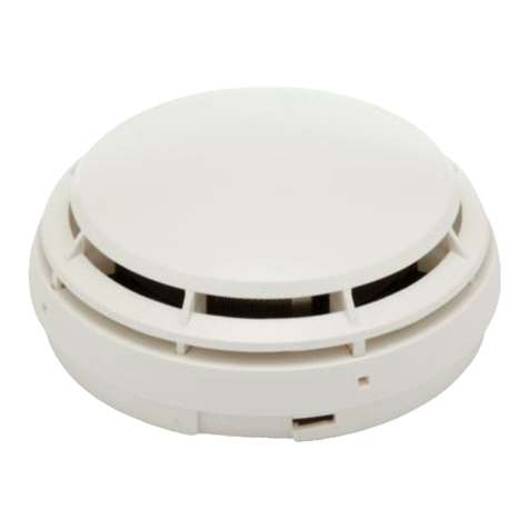
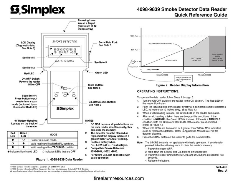
Simplex 4098-9687 User manual

4098-9687 Stand Alone Duct Detector
Installation Instructions
574-777
Rev. B
firealarmresources.com

Blank Page
firealarmresources.com

NOTICE
THIS DEVICE IS A STAND ALONE DUCT DETECTOR. IT IS DESIGNED
TO SAMPLE THE AIR FLOW PASSING BY IT IN THE AIR DUCT TO
DETERMINE WHETHER IT CONTAINS UNACCEPTABLE LEVELS OF
SMOKE.
THE EFFECTIVENESS OF A STAND ALONE DUCT DETECTOR IS
HIGHLY DEPENDENT UPON:
•THE DESIGN AND OPERATING CONDITIONS OF THE AIR HANDLING
SYSTEM IN WHICH IT IS INSTALLED;
•VARIABLES SUCH AS SMOKE DILUTION AND STRATIFICATION OVER
WHICH EVEN THE BEST DESIGNED SYSTEMS HAVE NO CONTROL;
AND,
•PROPER PLACEMENT AND POSITIONING OF THE STAND ALONE
DUCT DETECTOR, WHICH IS OFTEN COMPROMISED FOR
PRACTICAL REASONS.
FOR THE REASONS STATED ABOVE, THE EFFECTIVENESS OF THE
STAND ALONE DUCT DETECTOR CANNOT BE WARRANTEED OR
GUARANTEED. UNDER NO CIRCUMSTANCES SHOULD THIS STAND
ALONE DUCT DETECTOR BE USED AS OR REGARDED TO BE A
SUBSTITUTE FOR THE BUILDING’S REGULAR FIRE ALARM AND
DETECTION SYSTEM.
THE NFPA STATES THAT DUCT SMOKE DETECTORS MUST NOT BE
USED AS SUBSTITUTES FOR OPEN AREA PROTECTION. DO NOT
CONNECT THE STAND ALONE DUCT DETECTOR TO A FIRE ALARM
CONTROL PANEL. THIS UNIT IS INTENDED AS A STAND ALONE DEVICE
FOR USE IN THE CONTROL OF AIR HANDLING EQUIPMENT FOR THE
PURPOSES OF CLOSING DAMPERS OR SHUTTING DOWN AIR
HANDLING UNITS.
firealarmresources.com

Blank Page
firealarmresources.com

Table of Contents............................................................................................................................................. iii
General Description..........................................................................................................................................1
Introduction....................................................................................................................................................1
Electrical Specifications....................................................................................................................................3
4098-9687 Stand Alone Duct Detector Housing ...........................................................................................3
4098-9842 Duct Control Station........................................................................................................................6
Operation.......................................................................................................................................................6
Installation.........................................................................................................................................................8
Pre-Installation Routines ...............................................................................................................................8
Rules to Follow..............................................................................................................................................8
Stand Alone Duct Detector Installation........................................................................................................10
Wiring Procedures.......................................................................................................................................12
Accessory Installation..................................................................................................................................13
Detector Replacement ................................................................................................................................14
AC or DC Operation Detector Testing.........................................................................................................14
Periodic Air Test..........................................................................................................................................14
Magnetic Test for Photoelectric Detectors..................................................................................................15
Preferred Method of Testing Smoke Detectors/Sensors ............................................................................16
Air Differential Pressure Test......................................................................................................................17
Maintenance................................................................................................................................................17
Template.........................................................................................................................................................18
Table of Contents
Suffix “C”or “CA”following an 8-digit Product ID number denotes ULC-listed product.
2000 Simplex Time Recorder Company, Westminster MA 01441-0001 U.S.A.
2000 Simplex International Time Equipment Co., Ltd., Mississauga, Ontario L4V 1H3 Canada.
All specifications and other information shown were current as of publication, and are subject to change without notice.
iii
firealarmresources.com

BLANK PAGE
Blank Page
firealarmresources.com

1
The 4098-9687 Stand Alone Duct Detector (see Figure 1 on page 2) is designed
to sample air and detect smoke in air ducts. The 4098-9687 duct detector uses
the 4098-9601 photoelectric smoke detector.
The 4098-9687 Stand Alone Duct Detector provides fail-safe operation, the loss
of power or detector removal activates the Duct Detector Housing alarm relay
contacts.
The 4098-9842 Duct Control Station (see page 6 for details) is the remote
control interface connected to the Stand Alone Duct Detector and provides a
Power-On LED, Alarm LED, audible sounder, sounder silence switch, and
detector Test/Reset switch.
For detailed information on using smoke detectors in air distribution systems, see
NFPA 90A and refer to the following excerpt from NFPA 90A.
Per NFPA 90A, 1999 Edition
Section 4-4.4.3 Where smoke detectors required by Section 4-4 are installed in
a building not equipped with an approved fire alarm system as
specified by 4-4.4.2, the following shall occur:
1. Smoke detector activation required by Section 4-4 shall cause a visual and
audible signal in a normally occupied area.
2. Smoke detector trouble conditions shall be indicated visually or audibly in a
normally occupied area and shall be identified as air duct detector trouble.
Continued on next page
General Description
Introduction
firealarmresources.com

2
Figure 1. Stand Alone Duct Detector Components
General Description, Continued
HOUSING COVER
#8 CAPTIVE PANHEAD
SCREW
QTY: 4 DETECTOR MAGNETIC
TEST LOCATION 3/4" CONDUIT ENTRY
# 12-18 AWG WIRE
RECOMMENDED
PCB ASSEMBLY
DETECTOR BASE
HOUSING BASE
4098-9601
SMOKE DETECTOR
COVER GASKET
BASE GASKET
SMOKE PORT/AIR FLOW
TEST HOLES
CAP PLUG
SHIP GROUP 748-518
SEE NOTE
PLACE MAGNET HERE
TO TEST
Note: Two 3/4" conduit entries are provided for field wiring
connections (#12-18 AWG) to the PCB assembly. The
unused conduit entry is sealed off using the cap plug
(ship group 748-518). Apply even pressure on the
plastic cap plug to secure it against the conduit plate.
The cap plug seals and removes easily with moderate
pressure.
STATUS LED
firealarmresources.com

3
The 4098-9687 Stand Alone Duct Detector can be powered from 24 VDC, 24 VAC, or
120 VAC power sources. Separate terminal block connections are available for the
24 VDC/VAC or the 120 VAC power sources. When the 120 VAC connection is used,
no connections should be made to the 24 VDC/VAC inputs.
Note:The power sources must originate from a fused power supply listed for fire
protection signaling use, or from the Fire Alarm Control Panel (FACP) power
supply.
Listed below are the electrical specifications for the 4098-9687 Stand Alone Duct
Detector configurations:
24 VDC Power Operation (Figure 2, Page 4)
•Input Voltage – 20.4 to 32 VDC
•Standby Current – 40 mA at 24 VDC maximum
•Alarm Current – 50 mA at 24 VDC maximum
•Control Contacts - Alarm Relay - Dry SPDT
K1 N.O. (TB2-1), K1 C (TB2-2), K1 N.C. (TB2-3)
Note: All relay contacts rated 5 amp at 24 VDC/VAC; or 120 VAC resistive
nonpower-limited.
24 VAC Power Operation (Figure 2, Page 4)
•Input Voltage – 20.4 to 32VAC
•Standby Current – 100 mA at 24 VAC maximum
•Alarm Current – 125 mA at 24 VAC maximum
•Control Contacts - Alarm Relay - Dry SPDT
K1 N.O. (TB2-1), K1 C (TB2-2), K1 N.C. (TB2-3)
Note: All relay contacts rated 5 amp at 24 VDC/VAC; or 120 VAC resistive
nonpower-limited.
120 VAC Power Operation (Figure 3, Page 5)
•Input Voltage – 102 to 132 VAC, 60Hz
•Standby Current – 30 mA at 120 VAC maximum
•Alarm Current – 40 mA at 120 VAC maximum
•Control Contacts - Alarm Relay - Dry SPDT
K1 N.O. (TB2-1), K1 C (TB2-2), K1 N.C. (TB2-3)
Note: All relay contacts rated 5 amp at 24 VDC/VAC; or 120 VAC resistive
nonpower-limited.
Continued on next page
Electrical Specifications
4098-9687 Stand Alone Duct
Detector Housing
firealarmresources.com

4
1
TB1 TB2 TB3
2 3 4 5 6 7 8
LED
AP 120 GND NEUNO C NC- TEST24V
1 2 3 4 5 6
LED
AP- TEST
SEE NOTE 2
SEE NOTE 3
NOT USED
24 VDC OR 24 VAC
POWER SOURCE
FUSED
4098-9842
DUCT CONTROL STATION
1 2 3 3 4 5
UNIT
BEING
CONTROLLED
TURNS OFF (OPEN CONTACTS)
ON ALARM OR DETECTOR REMOVAL
OR LOSS OF POWER
4098-9687
STAND ALONE
DUCT DETECTOR
Figure 2. Wiring the 4098-9687 Stand Alone Duct Detector for 24 VDC or 24 VAC Operation
Continued on next page
Electrical Specifications, Continued
Notes:
1. Stand Alone Duct Detector wiring is 12 to 18 AWG.
2. Maximum allowable wire run from Stand Alone Duct
to Duct Control Station is 500 feet.
3. All relay contacts rated 5 amp at 24 VDC/VAC; or
120 VAC resistive non-power-limited.
firealarmresources.com

5
4098-9687
STAND ALONE
DUCT DETECTOR
12345678
LED
AP 120 GND NEUNO C NC- TEST24V
1 2 3 4 5 6
LED
AP- TEST
SEE NOTE 2
SEE NOTE 3
NOT
USED TO 120 VAC
SOURCE
FUSED
GREEN
GROUND
SCREW
(SEE NOTE 4)
CONNECT GROUND TO
GROUND SCREW PROVIDED
ON DUCT HOUSING
4098-9842
DUCT CONTROL STATION
123 345
UNIT
BEING
CONTROLLED
TB1 TB2 TB3
TURNS OFF (OPEN CONTACTS)
ON ALARM OR DETECTOR REMOVAL
OR LOSS OF POWER
Figure 3. Wiring the 4098-9687 Stand Alone Duct Detector for 120 VAC Operation
Electrical Specifications, Continued
Notes:
1. Stand Alone Duct Detector wiring is 12 to 18 AWG.
2. Maximum allowable wire run from Stand Alone Duct Housing to Duct
Control Station is 500 feet.
3. All relay contacts rated 5 amp at 24 VDC/VAC; or 120 VAC resistive
nonpower-limited.
4. Loop ground wire around green ground screw.
firealarmresources.com

6
The 4098-9842 Duct Control Station (Figure 4) provides the following switches
and indicators for the Stand Alone Duct Detector. Refer to Table 1 on the
following page for the Duct Control Station status list descriptions.
4098-9842 DUCT CONTROL STATION
POWER
ALARM
NORMAL
TEST/
RESET
SILENCE
SILENCE
Figure 4. Duct Control Station
When the Stand Alone Duct Detector is in alarm or the detector removed, the alarm
relay contacts transfer, the Duct Control Station audible sounder activates, and the
red “ALARM”LED illuminates (on steady). A toggle of the Duct Control Station
silence switch silences the audible sounder, but does not affect the alarm relay
contacts of the Stand Alone Duct Detector. Upon detector removal, the green
“POWER”LED also goes out.
To reset the Stand Alone Duct Detector after an alarm condition perform the
following steps:
1. Ensure all smoke or aerosol has been purged from the smoke detector in the
4098-9687 Stand Alone Duct Detector.
2. At the 4098-9842 Duct Control Station, rotate the Key Switch to the
“TEST/RESET”position for two seconds. Return the Key Switch to the
“NORMAL”position.
3. The red “ALARM”LED turns off and all the control functions return to
normal operation.
Note: When the detector is removed from the Stand Alone Duct Detector,
turning the Key Switch to the “TEST/RESET”position and back to the
“NORMAL”position does not deactivate the red “ALARM”LED or the
alarm relay contacts of the Stand Alone Duct Detector.
When power is removed from the Stand Alone Duct Detector, the Duct Control
Station green “POWER”LED goes out. The red “ALARM”LED and audible
sounder do not activate, but the alarm relay contacts on the Stand Alone Duct
Detector transfer resulting in the damper closure or fan shutdown.
For test functions, when the Key Switch is set to the “TEST/RESET”position,
the red “ALARM”LED and audible sounder are activated and the alarm relay
contacts on the Stand Alone Duct Detector transfer. Once the Key Switch is put
back to the “NORMAL”position, the red “ALARM”LED and audible sounder
deactivate and the alarm relay contacts on the Stand Alone Duct Detector
return to the normal state.
Continued on next page
4098-9842 Duct Control Station
Operation
POWER ON
LED (GREEN)
SILENCE
TOGGLE
SWITCH
ALARM LED
(RED)
TEST/RESET
SWITCH
AUDIBLE
SOUNDER
firealarmresources.com

7
Table 1. Duct Control Station Status List
Indicator
Mode Power-On
LED Alarm LED Sounder Control Relay
Normal On Off Off Deactivated
Alarm All On
Missing Detector
Head Off On On
Trouble Power Fail All Off
Activated
4098-9842 Duct Control Station, Continued
firealarmresources.com

8
The 4098-9687 Stand Alone Duct Detector should be installed in a location of
relatively nonturbulent air flow and within the intended operating velocity range
of 300-4000 feet-per-minute (91 to 1220 M/min.).
Simplex recommends measurements of air flow and examination of engineering
specifications that define expected duct air velocities under all conditions. This
is done to determine if a location is suitable for duct detector operation. An
Alnor Instrument Co. (Chicago) Model 6000P Velometer or equivalent (not
supplied) may be used to check the duct air velocity.
1. It is recommended to locate duct detectors a minimum of six duct widths
downstream from bends or inlets. Such locations ensure that air flow is non-
turbulent and that smoke is properly mixed with air in the duct for maximum
detector efficiency. See Figures 5 and 6.
Note: Installation of a duct detector/sensor to a round duct is the same as
shown in Figures 5 and 6 as long as the round duct is 18 inches or
larger (45.7 cm) in diameter.
6 DUCT WIDTHS
MINIMUM
BEND OR OTHER
OBSTRUCTION
Figure 5. Duct Detector Placement - Location of Bends or Inlets
6 DUCT WIDTHS
MINIMUM
RETURN AIR
INLET
Figure 6. Duct Detector Placement - Location of Air Return Inlet
2. Locate duct housings so that dampers do not restrict air flow at the detector
location. See Figure 7.
Continued on next page
Installation
Pre-Installation Routines
Rules to Follow
firealarmresources.com

9
DETECTOR
EXHAUST
FRESH
AIR
INTAKE
RETURN
AIR
SUPPLY
AIR
DO NOT LOCATE
DETECTOR HERE
RETURN AIR
DAMPER
DETECTOR (O.K.)
FILTER
BANK
EXHAUST
DAMPER
DO NOT LOCATE
DETECTOR HERE
Figure 7. Duct Detector Placement - Location of Dampers
3. Locate air duct detectors on the return or supply duct of the equipment’s air
handling system. However, detectors should NOT be installed in the return
air damper branch. See Figure 7.
4. Locate air duct detectors on branch lines if close identification of the alarm
source is required.
5. Locate air duct detectors on the downstream side of filters to sense fire in
filters. However, should the filters block, sufficient air flow may not be
available for proper air duct detector operation. See Figure 7.
6. Whenever possible, locate air duct detectors where they can be
conveniently observed and readily serviced.
7. Locate the air duct detectors in return air ducts ahead of mixing areas.
8. Do not locate air duct detectors next to outside air inlets unless you want to
monitor smoke entry to the handling system from an adjacent area.
9. Locate air duct detectors upstream of air humidifiers and cooling coils.
Continued on next page
Installation, Continued
Rules to Follow (continued)
firealarmresources.com

10
1. Tape the template (Figure 14) on the duct surface as shown in Figure 8.
Note: Do not position the template with edges angled with respect to air flow
direction (Figure 8).
2. Drill two 1 5/16-inch (33.32 mm) holes (marked “A”in Figure 14) as
located by the template. Remove template after holes have been drilled.
3. If the duct is more than 3 feet (0.9 m) wide, then punch a 1-inch (25.4 mm)
hole in the duct wall directly opposite the upstream 1 5/16-inch (33.32 mm)
hole. See Figure 9. This hole is used to support the inlet tube.
Figure 8. Template Positioning
Inlet Tube Selection
4. Inlet tubes should be selected and cut to length as specified in Table 2
(Page 11). After trimming the inlet tube opposite the slot, tap rubber plug
(supplied) into the trimmed end. See Figure 9.
TUBE SUPPORT HOLE ONLY FOR
DUCTS MORE THAN 3 FEET WIDE
INLET TUBE HOLES
FACE UPSTREAM
OF AIR FLOW
EXHAUST TUBE
DO NOT INSERT RUBBER PLUG
FOR DUCT WIDTHS
3 FEET TO 95 INCHES FOR DUCT WIDTHS
12 INCHES TO 3 FEET
INLET TUBE HOLES
FACE UPSTREAM
OF AIR FLOW
CUT EXHAUST TUBE TO 1/2 OF
DUCT WIDTH WHEN WIDTH
IS LESS THAN 24"
EXHAUST TUBE
DO NOT INSERT RUBBER PLUG
INSERT RUBBER PLUG
EXPECTED
AIR FLOW
DIRECTION
AIR FLOW
DIRECTION 12"
THIS END OF
INLET TUBE
Figure 9. Inlet Tube Orientation (Mounting Position 2 – See Figure 14)
Continued on next page
Installation, Continued
Stand Alone Duct Detector
Installation
HORIZONTAL DUCTS OVER 13" HIGH
OR
AIR FLOW
DIRECTION
OR
AIR FLOW
DIRECTION
HORIZONTAL DUCTS UNDER 13" HIGH
OR
AIR FLOW
DIRECTION
VERTICAL
DUCTS
NEVER MOUNT AT AN ANGLE
WITH RESPECT TO AIR FLOW
NO
firealarmresources.com

11
EXHAUST TUBE
INLET
TUBE RUBBER
PLUG
INLET TUBE HOLES FACE
UPSTREAM OF AIR FLOW
Figure 10. Inlet Tube Installation
Table 2. Inlet Tube Selection
OVERALL DUCT
WIDTH TUBE REQUIRED TUBE TYPE SUGGESTED TOTAL
LENGTH
12 inches (30 cm) 2098-9796 Hole
13 inches (33.02. cm) ½inch (1.27 cm)
longer than duct width
13 inches (33.02 cm) to
23 inches (58 cm) 2098-9804 Hole
24 inches (60.96 cm) ½inch (1.27 cm)
longer than duct width
23 inches (60 cm) to
46 inches (1.16 m) 2098-9797 Hole
49 inches (125.46 cm) 2 inches (5.8 cm)
longer than duct width
46 inches (1.16 m) to
71 inches (1.8 m) 2098-9798 Hole
73 inches (1.85 m) 2 inches (5.8 cm)
longer than duct width
71 inches (1.8 m) to
95 inches (2.4 m) 2098-9799 Hole
97 inches (2.45 m) 2 inches (5.8 cm)
longer than duct width
Housing Installation
5.Insert the inlet and exhaust tube receptors of the housing base into the two holes
previously cut in the duct.
6. Using the four #8 self-tapping sheet metal screws provided in the accessory kit,
locate the four mounting hole locations that are marked inside on the duct
housing plastic (Detector Chamber marked “MTG”). Drill the four self-tapping
screws through the housing plastic and duct sheet metal to secure the duct
housing (no pre-drilling is required). Torque screws 10-12 inch-pounds.
Inlet Tube Installation (See Figures 9 and 10)
7. Install the inlet tube by inserting the rubber plug end of the tube into the
upstream tube receptor located in the rear of the duct housing. The inlet tube
must be installed through the hole in the housing corner next to the smoke
port/air flow test holes. Place the tube retainer (supplied) over the inlet tube so
that the tab on the tube retainer goes into the slot on the inlet tube. Make sure
the tube retainer is in the proper orientation so that the holes in the inlet tube face
upstream into the airflow. The tab on the inlet tube retainer bracket indicates the
inlet hole side of the pipe.
Continued on next page
Installation, Continued
Stand Alone Duct Detector
Installation (continued)
TAB
SEE NOTE 1
INLET TUBE RETAINER
BRACKET
Notes:
1. The tab on the inlet tube retainer bracket indicates the inlet hole side of the pipe.
2. The inlet tube must be installed through the hole in the housing corner next to the
smoke port/air flow test holes.
SEE NOTE 2
firealarmresources.com

12
Note: If a support hole is being used, be sure to insert the inlet tube through
the hole on the far side of the duct.
8. Fasten the tube retainer using two #8 machine screws.
Notes:
A. Be sure to securely tighten the #8 machine screws to prevent accidental
turning of the tube within the receptor. Torque screws 16-18 inch-pounds.
B. If the inlet protrudes through the far side of the duct, seal the opening around the
tube (on the outside of the duct) with duct sealant.
Exhaust Tube Installation (See Figures 9 and 10)
9. Install the exhaust tube into the downstream receptor of the duct housing
base. Place the tube retainer bracket (supplied) over the exhaust tube so
that the tab on the tube retainer goes into the slot on the exhaust tube.
10. Fasten the tube retainer using two #8 machine screws.
Note: Be sure to securely tighten the #8 machine screws. Torque screws
16-18 inch-pounds.
If conduit is required, route conduit to the most convenient knockout and secure
to the assembly using suitable fittings.
Note: The unused conduit entry is sealed off using the cap plug (included with
ship group 748-518). Apply even pressure on the plastic cap plug to
secure it against the conduit plate. The cap plug seals and removes
easily with moderate pressure.
Connect wires to the appropriate terminals within the duct housing in accordance
with the wiring diagrams (Figures 2 and 3).
Perform all wiring in accordance with the requirements of the National Electric
Codeand local codes.
Connect the 4098-9842 Duct Control Station as specified in the following
paragraph and the associated installation and wiring diagrams (Figures 2 and 3).
Continued on next page
Installation, Continued
Stand Alone Duct Detector
Installation (continued)
Wiring Procedures
firealarmresources.com

13
The 4098-9842 Duct Control Station is intended for installation to a standard
double-gang outlet box having a depth of at least two inches. See Figure 11 for
basic mounting details. Make wiring connections in accordance with the wiring
diagrams (Figures 2 and 3) prior to attaching accessory to the box.
4098-9842 DUCT CONTROL STATION LISTED STEEL
DEVICE BOX
(BY OTHERS)
ACCESSORY
ACTUAL ACCESSORY MAY VARY
SLIGHTLY FROM PICTURE SHOWN.
POWER
ALARM
NORMAL
TEST/
RESET
SILENCE
SILENCE
Figure 11. Accessory Installation
Continued on next page
Installation, Continued
Accessory Installation
firealarmresources.com

14
To properly remove and replace the detector to the base (see Figure 1):
1. Remove power from the Stand Alone Duct Detector.
2. Loosen the four screws that secure the clear plastic cover to the housing base.
3. Insert a small blade screwdriver into the lock release slot in the base. Rotate
the detector counterclockwise to remove it from the base.
4. Remove dust cover from the replacement detector.
5. Insert the detector into the base and rotate until fully seated, continue
rotation until lock has been engaged.
6. Secure the clear plastic cover to the housing using the four screws (Torque
screw to 8-10 inch-pounds).
Note:An audible “snap”indicates proper contact engagement.
WARNING: System will not operate with dust cover in place.
Basic Unit Test
With power applied to the Stand Alone Duct Detector, introduce aerosol using the
553-673 Smoke Detector Aerosol Tester into the Duct Detector through the test
port holes (Figure 1). Or, place the 553-810 Magnet Tester next to the test
location on the clear Housing Cover (Figure 12). Observe “ALARM”LED
operation on the detector or the “ALARM”LED and sounder activation at the
4098-9842 Duct Control Station. Restore normal operation by momentarily
removing power, removing and replacing the detector head after aerosol has been
cleared from its chamber, or by activating the “TEST/RESET”switch at the
4098-9842 Duct Control Station.
With the air handling unit turned on, and all filters and dampers in place, open one of
the test port holes (Figure 1) by removing one of the red covers marked “Test”on the
unit. Measure the airspeed velocity inside the duct housing using the Alnor
Instrument Co. Air Velocity Meter (Model 8500) or equivalent (not supplied).
Note:Refer to manufacturer instructions when performing this test.
Insert the probe in the test opening and measure the airspeed directly in front of the
sampling tube. Airspeed measured at this point should be 200 fpm or greater.
Airspeed measured at the inlet is typically 40% –60% of the actual airspeed in the
duct housing. Any deviation from the recommended installation rules described
previously can cause this measurement to be unreliable.
If the airspeed measurement is less than 200 fpm, then a direct airspeed measurement
should be taken inside the duct. Airspeed inside the duct should be between 300 fpm
and 4000 fpm (91 to 1220m/min) for proper operation of the smoke detector.
Airspeed below 200 fpm measured inside of the duct detector may indicate a
sampling or exhaust tube obstructed by debris. Tubes should be inspected and
cleaned as required.
IMPORTANT: Make sure the test port covers are replaced after testing.
Continued on next page
Installation, Continued
Detector Replacement
AC or DC Operation Detector
Testing
Periodic Air Test
firealarmresources.com
Table of contents
Other Simplex Security Sensor manuals