DSC GSM 1000 User manual

INSTALLATION MANUAL
Version 1.O
Security Products
TM
• W A R N I N G •
Please refer to the System Installation Manual for information on limitations regarding product
use and function and information on the limitations as to liability of the manufacturer.

Table of Contents
Section 1 - Introduction......................................................................................................................1
1.1 GSM 1000 ..................................................................................................................................1
1.2 Specifications .............................................................................................................................1
Section 2 - Functions .........................................................................................................................2
2.1 Sending an Alarm.......................................................................................................................2
2.2 Trouble Supervision ....................................................................................................................2
2.3 Antenna Tamper.........................................................................................................................2
2.4 Downloading ..............................................................................................................................2
2.5 Emergency Calling .....................................................................................................................2
Section 3 - Installation .......................................................................................................................3
3.1 Cellular Communications ...........................................................................................................3
3.2 Mounting the Module in the Cabinet ..........................................................................................3
Hookup Diagram - PC1580.................................................................................................................4
Hookup Diagram - PC5010 / PC5015 / PC585 / PC1565 / PC5008...................................................5
Hookup Diagram - PC4010(CF) / PC4020(CF) / PC4020KT v1.0 to v2.X.........................................6
Hookup Diagram - PC4010(CF) / PC4020(CF) v3.X ..........................................................................7
3.3 Terminal Descriptions ................................................................................................................8
3.4 Mounting the Antenna ................................................................................................................9
Section 4 - Programming .................................................................................................................11
4.1 Programming the GSM 1000 Module.......................................................................................11
4.2 Setting up the GSM 1000 Programmer/PC ..............................................................................13
4.3 Programming the Control Panel ...............................................................................................14
Section 5 -Testing ............................................................................................................................17
5.1 Testing the System ...................................................................................................................17
5.2 Trouble Shooting ......................................................................................................................17
5.3 Trouble Indication ....................................................................................................................18
Section 6 - Glossary ofTerms .........................................................................................................20
The GSM 1000 unit is only
waranted for Contact ID service.
SIA or DOWNLOADING may not
work on your network.

1
SECTION 1 - INTRODUCTION
1.1 GSM 1000
The GSM 1000 Cellular Alarm Transmitter enhances the protection provided by a security system by
providing a reliable backup to the control panel’s normal telephone communications with the monitoring
station. The GSM 1000 works with the DSC Security Control Panels described in the Specifications below.
If the control panel is unable to complete an alarm transmission through the normal telephone line, due to
any line problems, the GSM 1000 will be activated and will transmit the alarm communication over the
cellular network. The GSM 1000 works automatically.
TheGSM1000hasbeendesignedforsimpleandstraightforwardinstallation.Wiringconnectionsaremade
directlybetweentheGSM1000unitandthesecuritycontrolpanel.TheDSCSecurityControlPanelrequires
only minor changes in their Programming Sections
1.2 Specifications
Compatible control panels
• PC585 v2.1 or later
• PC1565 v2.0 or later
• PC1580 v1.0 or later (except 1.0U).
• PC4010 v1.0 or later
• PC4020 v1.0 or later
• PC4020A v3.0 or later
• PC4020KT v1.0 or later
• PC5008 v2.0 or later
• PC5010 v1.0 or later
• PC5015 v2.0 or later
Cellular Network
• GSM 900 Mobile Communication Network.
RF Power Output
• 2.0 Watts peak
Antenna
• 3 - 5 dB gain, TNC connector
Battery
• 12 volt 7 Ah minimum rechargeable gel-cell type battery. It must be present on the control panel.
Dimensions
• 5.8" × 3.6" × 3.0" (148 mm × 90 mm × 77 mm)
Weight
• 1 lb. (0.5 kg)
IMPORTANT NOTE
A security system cannot prevent emergencies. It is only intended to alert you and, if included, a
monitoring station, of an emergency situation. Security systems are generally very reliable but they
may not work under all conditions and they are not a substitute for prudent security practices or life
and property insurance.Your security system should be installed and serviced by qualified security
professionals who should instruct you on the level of protection that has been provided and on
system operations.

2
SECTION 2 - FUNCTIONS
2.1 Sending an Alarm
When an event has occurred and a reporting code signal has to be sent to the monitoring station (i.e. an
alarm), the signal can be transmitted via the GSM network as a backup, primary* or redundant*
communicator. Please refer to the “Programming the Control Panel” section in this manual.
Backup
The control panel will check the telephone line for dial tone. If no dial tone is detected, the control panel
switches its communications path through the GSM 1000.
Primary
Thecontrolpanelwillnottrythetelephoneline,butwillimmediatelysendthesignalthroughtheGSM1000.
Redundant
The control panel will send the signal through the telephone line. It will attempt the call via the telephone
line until successful, or until the programmed maximum dialing attempts has been reached. After the
attemptonthetelephoneline,thepanelwillalwaysswitchtotheGSM1000tocommunicatethesamesignal.
* MAXSYS panels (PC40X0) can only use the GSM 1000 as a backup communicator.
2.2 Trouble Supervision
TheGSM1000monitorsitselffortwopossibletroubleconditions:PGMConnectiontothecontrolpanel,and
LossofCellularCommunications.LED1ontheGSM1000moduleisusedtoidentifywhichtroublecondition
is present. When a trouble condition is present, the TBL output will switch low, which in turn can trigger a
zone input on the control panel. Please refer to the “Trouble Indication” section in this manual for specific
detail on the trouble conditions and operation of LED1.
2.3 Antenna Tamper
TheantennatamperswitchmoduleprovidesextratampersecurityfortheGSM1000antenna.Notethatthis
tamper switch is effective if the antenna is mounted right at the module (no extension cable) and if the
antenna bracket on the GSM 1000 module is used. The switch dimensions are such that they fit on the
moduleexactlyifusedwith antennamounting bracket.Thereforeif theantenna isrelocatedtofitin another
hole, the tamper switch will generally be ineffective. Please refer to the diagram and mounting instruction
in the “Mounting the Antenna” section.
2.4 Downloading
If your GSM network has the required support, the GSM 1000 can be used for Downloading purposes to
aDSCcontrolpanel.ThisoptionalfeaturecanbeusediftheGSMnetworksupportsmodemcommunications
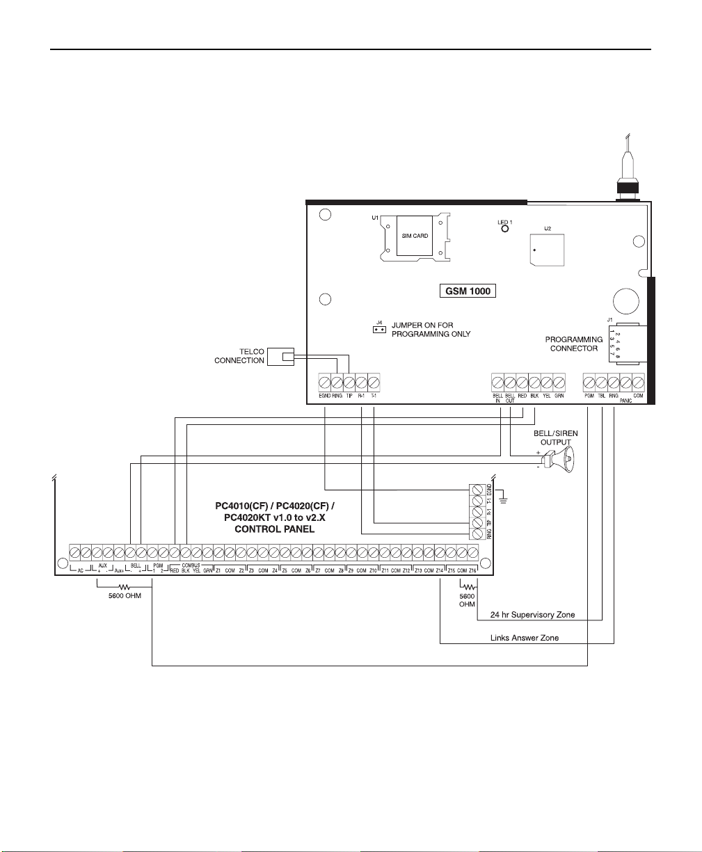
on its voice channel. Please refer to the RNG Terminal and Connection Diagram for proper connections.
Also, ensure Option 05 has been programmed accordingly, as indicted in “Programming the GSM 1000”
section in this manual.
Note: Downloading will only work if your GSM network supports SIA.
2.5 Emergency Calling
TheGSM1000iscapableofmakinganemergencycallviatheGSMnetwork,forsuchcasesaswhentheregular
telephone line is down. Simply by pressing the emergency button, the GSM 1000 will dial the preprogrammed
emergency telephone number. Please refer to the connection diagram in the “Panic Terminal” section and
telephone number programming in the “Programming the GSM 1000” section in this manual.
Note: It is recommended that the preprogrammed emergency number be that of a station with a 24-hr
attendant, such as your local monitoring station.

3
SECTION 3 - INSTALLATION
3.1 Cellular Communications
All cellular telephones, including the GSM 1000, must ‘register’ with the cellular network. ‘Registration’ is
simplyahandshakebetween the MobileservicesSwitching Centre and theGSM1000. During handshake
theinformationstored intheSIM cardis transmittedtothe GSMcell-siteand thecell-site–upon verification
of data- will send an authorisation back to the GSM 1000. It is therefore very important that a PIN number
beprogrammed intotheGSM1000
before
attempting toconnecttothenetwork.Registration isdoneupon
power up of the GSM 1000 and whenever requested by the network. If the GSM 1000 does not register the
network will not complete a call.
3.1.1 Arranging for Cellular Service
In order for the GSM 1000 to communicate via the cellular telephone network, an account must be set up
with a cellular network operator. The ‘account’ is simply a matter of establishing the billing information for
the cellular service. In return, the cellular carrier will provide you with a SIM card with PIN-number and a
telephone number
for your GSM 1000. Cellular service may vary in price and coverage. Check with your
GSM service provider for area coverage maps and service charges.
3.1.2 Inserting SIM Card
Whenyouhave obtainedaSIM card fromyourGSM serviceprovider,
insertitintotheSIMCardsocket(SIMLock)ontheGSM1000module.
Simplyslidethecoverto therightandpullopen.Theninsertyourcard
and close the lid.
3.2 Mounting Module in Cabinet
The metal bracket that accommodates the GSM 1000 is mounted in the upper right hand corner of the
control panel cabinet with the antenna going through the knock out. The GSM 1000 mounting bracket
attachestothepanelcabinetthroughtheuseofclipsandscrews.Pleasenote,however,thattheclips(metal
teeth) make it purposely difficult to remove the module once it is installed. Because of the nature of the
installation, it may be difficult to access the connection terminals of the control panel. It is therefore
recommended that wiring connections be made to the control panel before the module is installed.
There may be situations where the cabinet you are using does not accommodate the antenna mount
location properly. In such cases, you may order an optional cabinet, which will fit the GSM 1000 module
properly. You may also remove the antenna mast from the antenna bracket of the GSM 1000 module, and
reattach it through another hole in the cabinet you are using. Please ensure that antenna mast does not
contact the cabinet.
Note:Ifitisnotpossible to installtheantennawiththe antenna mastfastenedtotheantenna bracket ofthe
GSM 1000 module (i.e. relocating to another knock out), the antenna tamper switch cannot be used
effectively.
The GSM 1000 should not be located near sources of interference. These sources include EMI
(Electromagnetic Interference) generated by television or heavy electric motors, such as those found in
heating or air conditioning units.

4
HOOKUP DIAGRAM - PC1580

5
HOOKUP DIAGRAM -
PC585 / PC1565 / PC5008 / PC5010 / PC5015

6
HOOKUP DIAGRAM -
PC4010(CF) / PC4020(CF) / PC4020KT V1.0 TO V2.X

7
HOOKUP DIAGRAM - PC4010(CF) / PC4020(CF) V3.X

8
3.3 Terminal Descriptions
DonotconnectthetransformerorthebatterytothecontrolpaneluntilallotherwiringbetweentheGSM1000
moduleandthecontrolpanel, includingantenna connection,hasbeen completedand checked.Incorrect
wiring connections may cause the GSM 1000 unit to operate improperly. Please refer to the hookup
diagrams in the manual for the appropriate control panel that is used with the GSM 1000 module.
3.3.1 Earth Ground Terminal
Connect the GSM 1000 “EGND” terminal to the control panel “EGND” terminal. Connect a ground cable
fromtheCabinet Ground connectiontoan earthground,such asacoppercold waterpipe,by theshortest
and most direct route. Ensure that the cold water pipe connection provides path to ground.
Do not make
the ground connection to a plastic cold water pipe!
3.3.2 Telephone Line Terminals
The control panel TIP and RING are always used as the communications paths for the alarm signal. The
GSM1000controlswhetherthesignalisroutedthroughtotheregular telephoneline(PSTN)orviatheGSM
network. If the alarm signal is to go through the GSM network, the regular telephone line (TIP and RING of
GSM 1000) is disconnected.
3.3.3 BELL IN and BELL OUT Terminals
The GSM1000 module requires short durations of high current. The DSC control panel Bell output can
provide this current when the GSM1000 is transmitting. Please be sure to connect the Bell In and Bell Out
terminals as shown in the connection wiring diagrams.
3.3.4 Power Supply Connection
ConnecttheGSM1000“RED”terminaltothecontrolpanel“RED”terminalandtheGSM1000“BLK”terminal
tothecontrol panel“BLK”terminal. Forthe panelsthatdo nothavethe “RED”and“BLK” terminalsconnect
the GSM 1000 “RED” terminal to the control panel “AUX+” and the GSM 1000 “BLK” terminal to the control
panel “AUX-” terminal.
3.3.5 PGM Terminal
Theconnection betweenthecontrolpanelPGMterminaland theGSM1000PGMterminalprovidesaserial
communications link between the two boards. This link allows the control panel to send the central station
telephone number to the GSM 1000 Module.
Ensureaproperconnectionismade.Pleaserefertotheconnectiondiagramandprogramminginstructions
in this manual.
3.3.6 TBL (Trouble) Terminal
TheGSM 1000TBL terminalwill switchto groundwhenever atrouble conditionis presenton theGSM 1000
unit.Theterminalwillremainswitchedtogroundforaslongasatroubleconditionexists.Thisfeatureisused
to report GSM 1000 trouble conditions to the control panel via a zone programmed for 24 hour (Links)
supervision.
Please refer to the control panel programming instructions and wiring connection diagrams in this manual
to ensure proper supervision of the GSM 1000 module.

9
3.3.7 RNG (Ring) Terminal
WhentheGSM1000receivesaphonecall,itwillactivatetheRNGterminalontheGSM1000Module.Please
refer to Option 05 to enable ring detect. This output may be used for the control panel which allows it to
answer incoming downloading calls via the GSM network.
Note: Downloading is only available on networks capable of SIA communications.
Pleasereferto the controlpanelprogramming instructions inthismanual forprogrammingthe appropriate
input (i.e. Zone or PGM) as Links Answer or Forced Answer.
Please refer to the connection diagram in this manual for proper connections between the GSM 1000 and
control panel.
3.3.8 Panic Terminal
WhenthePanicterminalistemporarilyshortedtoground,
the GSM 1000 will dial the phone number that is
programmedinthepanicphonenumberoption.Please
refer to Option 09 in “Programming the GSM 1000
Module” section. This phone number has to be a direct
access line, it can not be dialed to a PBX and then into
an extension.
Note: This input is a 24-hour, silent terminal and the
Panic phone call will be connected through the cellular
network.
3.4 Mounting the Antenna
Note: The GSM 1000 antenna must be mounted above ground level.
Installing the antenna as high as
possibleisbest.Ifnecessary,AntennaExtensionKitsareavailablefromyoudistributor(seethe“Relocating
the Antenna” section below). The antenna should be installed in a physically secured location to avoid
tampering.Also,avoidplacingtheantennaunderanysortofRF(RadioFrequency)shielding,suchasmetal
roofing or overhang. The GSM 1000 works best when the antenna is installed in an unobstructed “line of
sight” to the GSM network receiver.
TheantennashouldalwaysbeconnectedtotheGSM1000wheneveritisoperated.Theunitwillnotfunction
properly if an antenna is not installed.
3.4.1 Antenna Tamper Switch
WhenthePanicterminalistemporarilyshortedtoground,
the GSM 1000 will dial the phone number that is
programmed in the panic phone number option. Please
refertoOption09in“ProgrammingtheGSM1000Module”
section.Thisphonenumberhastobeadirectaccessline,
it can not be dialed to a PBX and then into an extension.
In addition to the GSM 1000 network supervision, the
AntennaTamperSwitchmodulemay beusedtofurther
increase the security of the antenna connection to the
GSM 1000 module. Please refer to the diagrams below
for installing the tamper switch.
Note: This module is only effective if the antenna mast
is connected to the antenna bracket of the GSM 1000
module.

10
3.4.2 Relocating the Antenna
Before permanently mounting the control panel with the GSM 1000 module in its final location, verify that
it is working as it should by following these steps:
Step 1: Make all connections between the GSM 1000 and the control panel.
Step 2: Power up the control panel.
Step3:ChecknumberofflashesonstatusLEDontheGSM1000module.IftheLEDflashesonlyonceevery
10 seconds then the antenna is in an acceptable location.
If a suitable location is not available with the antenna attached directly to the GSM 1000 module, obtain an
Antenna Extension Bracket kit from your DSC / Sur-Gard supplier. Each kit contains an extension cable, a
mounting bracket, instructions, and all required mounting hardware. Three lengths of extension cable are
available:
Extension Kit Length of Cable
LAE-1 1 m
LAE-5 5 m
LAE-8 8 m
Use only the Extension Kits to extend the mounting range of the antenna. Do not cut or splice the
extension cable.
Themaximumdistance between theGSM1000 and theantennais 8 metersasobtained
by using the LAE-8 Extension Kit. Make sure the antenna is in a physically secured location to avoid
tampering.
Secure the TNC connector from the Extension Kit to the mounting bracket, ensuring that the star washers
make solid electrical contact with the mounting bracket.
Remove the antenna from the GSM 1000 metal bracket and connect the extension cable to the TNC
connector on the bracket/cabinet. Secure the antenna to the TNC connector mounted on the Extension Kit
Mounting Bracket.
Locate the mounting bracket and antenna away from possible sources of electrical interference. Moving
the antenna just a short distance will likely be adequate. Temporarily secure the mounting bracket in the
new location and repeat steps 1 - 3 above. If the test gives a good result, perform a test transmission as
described in the “Testing the System” section of this manual.
IfthetestissuccessfulandthecellulartransmissioniscompletedwithoutaLossofCellularCommunication
trouble, permanently secure the mounting bracket and antenna at the new location.
If the cellular transmission is not completed successfully or there is a trouble indication, relocate the
mounting bracket and test the GSM 1000 again.
Note: Do not secure the mounting bracket in a way that would stretch or strain the extension cable. Rather
than try to strain the cable to reach a desired location, use a longer cable. When installation is complete,
secure the extension cable so that it does not dangle or hang loose from the cabinet or mounting bracket.

11
SECTION 4 - PROGRAMMING
4.1 Programming the GSM 1000 Module
ThereareseveralprogrammableoptionsintheGSM1000.Theseoptionscanbeaccessedandprogrammed
in two ways: via the GSM 1000 Programmer (optional unit), or via your personal computer (PC) with Hyper
Terminal program. Both methods make a simple connection to the RJ-45 socket on the GSM 1000 module.
Please refer to connection diagram and the appropriate GSM 1000 Programming section below.
Note: Jumper J4 must be on when programming the module. Be sure to remove the jumper when you are
finishedprogramming.Also,besure to end your programmingsessionwiththe“0F” command to properly
exit and initialize the new settings.
4.1.1 Using GSM 1000 Programmer
The GSM 1000 Programmer is used to enter the required GSM cellular network parameters into the GSM
1000. If the parameters are not entered correctly, the GSM 1000 will not operate properly.
Connect the BLACK and RED wires of the programming unit to the “-” and “+” terminals of the standby
battery. Next, insert the SIM card to its holder and lock the card holder. Short jumper J4 and connect the
GSM1000ProgrammingUnit to RJ45connector.
Please note that GSM 1000 Programming Module has
to be connected to the system before power-up!
Applypower tothe wholesystem afterchecking allthe wiringbetween thecontrol paneland theGSM 1000
module. After about 10 seconds the LCD display should show the “Enter Password” message. The
passwordisA1AA55.Enterthepasswordterminatingthelinewith<ENTER>.ThePasswordcanbeentered
2 times only. After 2 wrong attempts the GSM 1000 unit will lock you out. All data strings have to be
terminated with <ENTER>..
..
. Upper case letters from A to F can be produced by pressing <1 to 6> while
depressing the <SHIFT> button. Please see following chart:
Keys depressed LCD display
0 to 9 0-9
<SHIFT> + 1 A
<SHIFT> + 2 B
<SHIFT> + 3 C
<SHIFT> + 4 D
<SHIFT> + 5 E
<SHIFT> + 6 F
The next message will be: “Selection:” Enter the number representing the feature you want to program or
changeandthe<ENTER>attheend.Youhavetoenteratwo-digitnumberfor“Selection”.Ifthefirstnumber
is 00
00
0, the unit will perform EDITing of the options; and if it is 1, it will perform DIAGNOSTICS function.
Options
The following options can be EDITed:
00 Display software version
01 Display PCB revision
02 Set number of Cell error before reporting error to panel
03 - 04 For future use
05 Ring Detect (EEPROM flag)
06 - 07 For future use
08 PIN number
09 ‘PANIC’ phone number
0A - 0D For future use
0E Return to Selection mode
0F Exit Programming mode

12
Explanation of EDITable options:
O: xx = Old value
N: yy = New value to be entered
yy = Must be 2 digit value, e.g. O:02, N:03.
Press <ENTER> to save value and exit option.
Press <ESC> to exit option without changing the existing value.
00: Display software version.
Displays the current software version.
Line 1: Software ver.
Line 2: = 5A0100
01: Display PCB revision.
Displays the current version of GSM 1000 board.
Line 1: PCB ver.
Line 2: = 100000
02: Set number of Cell error before reporting errors to control panel.
Number of “Cell/Transceiver” problems before reporting the problem to the control panel
Line 1: Cell error
Line 2: O: xx, N: yy
Note: This value must not be “00”. The factory default value is “04”.
05: Ring Detect (EEPROM flag)
Ifenabled,theGSM1000candetectincomingcallsuchasadownloadingcall.TheRNGoutputwillactivate
when a call is incoming.
02 = Ring Detect Enabled
00 = Ring Detect Disabled
Line 1: E2prom flag
Line 2: O: xx, N: yy
08: PIN number.
Users 4 digit PIN number. Must be entered to make a call on GSM 1000
Line 1: PIN num.
Line 2: O: x, N: y
y = 1 digit value. Repeat entry until all 4 digits of your new PIN is complete.
09: ‘PANIC’ phone number.
Phone number to dial after the ‘Panic’ button is pressed.
The old phone number is displayed as
Line 1: Panic old: 123
Line 2: 4567890123456
The new phone number can be entered as
Line 1: Panic new: 123
Line 2: 4567890123456
A maximum of 16 telephone digits can be entered.
0E: Return to selection menu
0F: Exit programming mode
Note: Make sure you always exit the programming mode with the OF command. Remove the GSM 1000
programmer/PC from J1 and remove the jumper from J4.

13
4.1.2 Disconnecting GSM 1000 Programmer
Step 1Step 1
Step 1Step 1
Step 1
Remove the BLACK and RED wires from the standby battery.
Step 2Step 2
Step 2Step 2
Step 2
Disconnect the modular cord of the Programmer Unit from the GSM 1000.
Step 3Step 3
Step 3Step 3
Step 3
Remove Jumper J4 from GSM 1000 module.
Step 4Step 4
Step 4Step 4
Step 4
Make sure that the SIM card is securely seated in its socket and the holder is latched.
Step 5Step 5
Step 5Step 5
Step 5
Observe the proper flashing rate of the red LED. It should only flash once every ten seconds.
Note: Unplug the Programmer from the GSM 1000 when finished programming. The GSM 1000 will not
operate when the Programmer is plugged in.
4.1.3 Using a PC (Personal Computer)
Programming can also be done using a personal computer and a GSM 1000 programming cable (Order
at Sur-Gard Part #: 19000855). For hook up and details please refer to Programming Hookup diagram.
Use the following setup:
Start ‘Hyper Terminal’ software under Windows and set the communication options to:
• Baud rate: 1200 • Parity: even • Data bits: 7 • Stop bit: 1 • Flow control: none
PoweruptheGSM 1000 moduleandthenconnect the GSM1000Programmingcable to J1(RJ45socket).
Note: Jumper J4 should be ON when programming the unit via PC or GSM 1000 Programmer. Remove
jumper when programming is complete.
4.2 Setting up the GSM 1000 Programmer/PC

14
4.3 Programming the Control Panel
IMPORTANT NOTE
When a control panel is programmed for GSM 1000 operation, the PGM1 output is dedicated to the
GSM 1000 Communicator and cannot be used for other functions.
The GSM 1000 utilizes and relies on the features and functionality in DSC control panels which are
present for the Links1000 Communicator. Therefore, any reference in the control panel’s installa-
tion manual to Links1000 programming also applies to the GSM 1000.
4.3.1 Telephone Number Preamble
TheGSM1000receivesthetelephonenumbertodialfromthealarmcontrolpanel
telephonenumber
memory
location.The‘data’issent viathe PGMconnection.The ‘Preamble’programming sectionofthealarmcontrol
allows for flexible dialing strings. This helps the installer use the most effective cellular plan available.
The‘Preamble’ allowsthe installerto adda prefixor acountry andarea codeto thetelephone numbershould
the cellular network need additional dialing digits. In some areas, dialing the central monitoring station may
onlyrequiresevendigitswhenusinglandline,whilethecellularnetworkmayrequirecountrycode+areacode
+ a common specified phone number accessing the network. Still other areas may require what is known as
‘0 plus’ dialing. That is, the cellular network requires a ‘0’ be added to the local telephone number.
Ifthereissomedoubtwhethera‘Preamble’isneeded,simplydialthecentralstationfromthepremisesland
line, then, dial the number using the installed GSM 1000. If both calls connect, do not add a ‘Preamble’.
To add a ‘Preamble’ simply enter the additional digits required in the location provided (see Control Panel
Programming section). The ‘Preamble supports up to 4 digits and they will always be dialed in front of the
telephonenumberinthe control panelmemory.Factory default of‘Preamble’location is FFFF. Programall
unused digits as “F”.
4.3.2 Communication Formats
DuetolimitationoftheGSMcellulartelephonenetwork,onlycertaincommunicationformatsarerecommended
when using the GSM 1000:
••
••
•Recommended:Recommended:
Recommended:Recommended:
Recommended: DTMF formats (i.e. Contact ID)
••
••
•Not Recommended:Not Recommended:
Not Recommended:Not Recommended:
Not Recommended: Pulse formats (i.e. 20 BPS)
••
••
•Depends on network:Depends on network:
Depends on network:Depends on network:
Depends on network:
Modem Format (i.e. SIA)
4.3.3 PC1580
Section(s)
[01] Choose a zone for GSM 1000 TBL supervisory and program as zone definition ‘09’.
[06] Programmable Output Options. Enter ‘16’ in this section to enable GSM 1000 operation for PGM1. If
Downloadingviacellularistobeused,thenenter‘30’forPGM2,otherwiseprogramPGM2asdesired
or hit ‘#’ to exit. Only PGM1 supports GSM 1000 operation and only PGM2 supports Forced answer.
[36] Program the Alarm Reporting Code for the GSM 1000 24-hour Supervisory Zone. The restoral
code is in section 37.
[43] Program reporting code for TLM (telephone line monitor). The restoral code is in section 44.
The restoral will not be sent via GSM 1000.
[46] Program Test Transmission Reporting Code.
[51] Program Call Direction for sending alarms. Minimal setting for GSM 1000 operation is option 3 ‘ON’.
[52] Program Call Directions for tamper alarm and restorals. Default is ‘Disabled’.
[53] Program Call Directions for Openings and Closings. Default is ‘Disabled’
[54] Program Call Directions for System Maintenance Alarms. Default is ‘Disabled’
[55] Program Call Directions for System Test Transmission. Minimum setting for GSM 1000 opera-
tion is option 3 ‘ON’.
[61] Program Second Communicator Option Code. Default is ‘GSM 1000 used as land-line backup
communications only’.
[62]-[63] GSM 1000 Test Transmissions will follow System Test depending on programming in sections
[46] and [55].
[67] Program GSM 1000 Preamble. Please see 4.3.4 Preamble section. Sections [68] and [69]
used for second and third Preamble numbers.

15
4.3.4 PC585 / PC1565 / PC5008 / PC5010 / PC5015
Programming the Control Panel
Section(s)
[001]-[004] GSM 1000 Supervisory:
choose the zone that will be used to report the 24 hour GSM 1000
supervisory alarms [section 001 to 004]. Program that zone as [09].
Downloading via GSM 1000: if Downloading via cellular is to be used, choose a zone to
perform Forced Answer. Program the chosen zone as [24]. This will force the panel to answer
an incoming cellular call.
[009] GSM 1000 Enable: program [16] into section 009. This will reserve the PGM1 output for GSM
1000 communications. Only PGM1 will support GSM 1000 operation.
[320]-[323] GSM 1000 Trouble Reporting Code:
in section 320 to 323, enter the desired reporting code
for GSM 1000 Trouble reporting. Use same zone as GSM 1000 supervisory.
[349] TLMTrouble Reporting via GSM 1000: go to section 349. Find TLM Trouble Code (via GSM
1000). Enter the desired reporting code. The Restoral is contained in section 350, this will not
be sent via the GSM 1000.
[352] GSM 1000TestTransmission: program the GSM 1000 Test Transmission code in section 352.
The GSM 1000 will follow the land line test transmission schedule.
[361]-[368] GSM 1000 Call Direction Options: go to sections 361 to 368. Determine which signal types
will be sent via GSM 1000. Section 380, zone light [7] dictates whether the GSM 1000 will be
used as backup or primary communications. When set to primary, the GSM 1000 will always
place a cellular call on signals so identified in Call Directions.
[390]-[392] GSM 1000 Preamble:
program sections 390 to 392 with preambles (if necessary) for each
communicator outbound telephone number.
[490] GSM 1000 Downloading Preamble: if necessary, program section 490 with the GSM 1000
Preamble for the Downloading.
[703] Dialing Delay: program section 703 with 010. This places a necessary delay between GSM
1000 (and all other) dial attempts.
4.3.5 PC4010 / PC4020 / PC4020KT
To program the panel for GSM 1000 operation, enter the “Links 1000” section, which can be found under
System (00), Communications (04) and then Links1000 (04). Programming the following items, as
described in further detail below: Links Enable/Disable, Links telephone number, and Periodic Test
Transmission.
Programming GSM(Links) 1000 Telephone Numbers
Enterthetelephonenumberthewayitwouldbedialedonatelephone.Thetotalnumberofdigits,including
dialtonesearches,mustnotexceed31.Notethata“D”fora dialtone searchis automaticallyprogrammed
at the beginning of the telephone number.
Note: There must be a dial tone search programmed into the
telephone number for the GSM 1000 module to operate.
When a telephone number is entered, press the [#] key to save the number in the system’s memory.
PC4010/PC4020/PC4020KT Telephone Entry Options Menu
Press the [*] key to enter the Telephone Entry Options Menu. Use the arrow keys to scroll through the list
of menus, and press the [*] key to select the menu displayed on the keypad screen. Or, enter [0] or [1] to
select one of the menu options described below:
[0] Save Afterentering atelephonenumber, instead ofpressingthe [#]key,this optionmaybe selected
to save the number in the system’s memory.

16
[1] Dial Tone Selecting this option will add a 2-second dial tone search to the telephone number. The
dial tone search will be represented by a “D” in the telephone number display. A dial tone search forces
the control panel to wait for a dial tone before dialing a telephone number.
The following PC4010/PC4020/PC4020KT Menu Items are not used while programming telephone
numbers for GSM 1000 operation. Do not select these items while programming telephone numbers for
GSM 1000 operation, as adding pauses or the DTMF digits may result in improper dialing.
[2] Pause 2 Seconds [4] DTMF *
[3] Pause 4 Seconds [5] DTMF #
Links Module - The PC4010/4020/4020KT panels must be programmed to work with the GSM1000
module. This is done by enabling the LINKS module. Doing so automatically enables the PGM1 Output
for GSM1000 operation.
Periodic Test - A periodic test transmission can be sent through the GSM network. This option must be
turned on to be enabled.
Transmission Cycle Days - Enter the number of days between test code communications. Valid entries
are from 001 to 255; the default setting is 030.
Transmission Cycle Time - Enter the time of day for the test transmission. Enter the time in the 24-hour
clock format, where the first 2 digits are the hours ranging from 00 to 23, and where the last 2 digits are the
minutes ranging from 00 to 59. The default setting is 0000.
GSM 1000 Trouble Reporting - Program Zone 1 trouble reporting code, and restoral reporting code.

17
SECTION 5 - TESTING
5.1 Testing the System
Before testing the GSM 1000 unit, ensure that the control panel is correctly programmed and operating
properly by performing a test transmission to the monitoring station over the normal telephone line. If
problemsareencounteredincommunicatingoverthenormaltelephoneline,ensurethatthecommunication
options, telephone numbers and account numbers are programmed properly in the control panel. The
control panel must be programmed properly in order for the GSM 1000 to operate.
Apply power to the whole system after all wiring connections have been made. Ten seconds after power
isappliedto the GSM1000unit, LED1 ontheunit will begintoflash. Observe LED1forat least 40seconds,
if LED1 flashes once every ten seconds, then the GSM unit is operating properly. If there is a trouble
condition, LED1 will flash either
four
times or
eight
times in every ten seconds. Refer to the “Trouble
Indication” section of this manual.
5.1.1 Performing a Test Transmission
Contact the monitoring station to request a transmission test. Remove the telephone cord from the TELCO
jack. Perform a System Test as described in the control panel’s Installation Manual. When the test is
complete,contactthe monitoringstation toconfirmthe transmission.Performadditionaltesttransmissions
as required by the monitoring station.
Note: Whenever a cellular telephone call is answered by a receiver or another phone, cellular charges will
be applied to the cellular telephone account that placed the call. Therefore keep in mind that test signals
willincrementthecellularbill. If for somereasonthecall is established butthealarmsignalis not received,
the cellular account will still be billed. Please double check the installation before you test.
5.1.2 “On Air” Indication
Wheneverthe GSMunitiscommunicatingoverthecellular network,theredLED(LED1)ontheunit’s circuit
board will be energized. When communications are successfully completed and there are no troubles to
report,the LEDwillreturntoitsstandby indicationofoneflashevery10 seconds.Iftroubleconditionsexist,
the LED will flash 4 or more times every 10 seconds.
5.2 Trouble Shooting
If GSM 1000 does not communicate to the central monitoring station receiver, check the following before
calling Technical Support:
5.2.1 Check Wiring
A. Make sure T1 & R1 of the GSM 1000 are connected to TIP & RNG of the control panel.
B. Make sure the RED and BLK of the GSM 1000 are connected to RED and BLK of the control panel.
C. Make sure the BELL+ of the panel is connected to BELL IN of the GSM 1000. The BELL OUT should
be connected to the siren.
D. Make sure the proper resistor is in place on control panel PGM (see installation instructions).
E. Make sure the programmer is not plugged into the GSM 1000.
F. Make sure jumper J4 is removed.

18
5.2.2 Check Trouble LED
A. Check number of flashes on status LED. If the LED flashes more than once every ten seconds, refer
to Table 1 in the “Trouble Indication”section and correct the indicated problem.
B. Fourflashesindicatesbadcommunicationswiththecellularnetwork.Tryaddinganextension antenna
and relocating the antenna.
C. Eightflashes indicatesa badPGM connection.Checkthatthewirefromthecontrolpanel’sPGMto the
GSM 1000 PGM is correct and that the correct resistor is in place. Next, check that the power
connections(RED, BLK,BELL+)betweenthepaneland theGSM1000aregood.Lastly,verifythat the
control panel is programmed for GSM 1000 operation.
5.2.3 Other Checks
A. Connecta telephonehandsettoTIP& RINGof thecontrolpanel. Senda signalthroughtheGSM1000.
Listen to the handset. If a ‘network’ message is heard, make note of it and follow the instructions. For
instance; the network message says “you must first dial a 1 or zero before placing this call”. The
telephone number in the control panel probably requires a ‘Preamble’.
B. Check cellular activation. Call the cellular number of the GSM 1000. If the GSM 1000 is properly
activated but turned off, the network message should say “the cellular customer you have called is
unavailable or has travelled outside of the coverage area”. If the GSM 1000 cellular number is called
andthe GSM1000isturnedon(and downloadingisnotenabledandconnected), themessageshould
say“Thecustomeryouhavecalledisunavailable”,orit willsimplyhangup(thiswouldoccuraftermany
rings). If the cellular number is not activated the message will say “the number you have called is not
in service”. Call the cellular service provider and check the activation. Be prepared with the GSM
Cellular Service Provider Information.
C. If you continue to experience difficulties, try sending a signal through the GSM 1000 and listen for the
black relay on the GSM 1000 board to ‘click’. This indicates that the GSM 1000 is receiving the central
station telephone number via the control panel PGM output. If after that the red trouble LED stays on
steady, the GSM is transmitting. If it does not, the GSM 1000 can not find a voice channel. The panel
will time-out and attempt the call again. Try using an antenna extension kit to relocate the antenna.
Note: Do not disconnect the telephone line between the GSM 1000 and control panel when testing. Only
disconnect the telephone line at the TELCO jack when testing the GSM 1000.
5.3 Trouble Indication
The GSM 1000 automatically monitors its operation and indicates trouble conditions by flashing LED1 on
the circuit board. LED1 normally flashes once every 10 seconds when the GSM 1000 is in standby (ready
to transmit) mode. Troubles are indicated when LED1 flashes more than once at each 10 second interval.
Shown below is the number of flashes used to indicate each trouble condition. If more than one trouble is
present, only the first trouble is indicated. When that trouble is cleared, the next will be indicated.
The GSM 1000 uses a 30-second delay timer for all troubles. The status LED will flash as soon as the
conditionisdetected,buttheTBLoutputwillnotbeactivateduntiltheconditionhasexistedfor30seconds.
TABLE 1 — LED1 Indications
Number of LED Flashes Trouble Time-outs for GSM 1000 failures
4 flashes Loss of Cellular Communication 30 seconds
8 flashes PGM Trouble 30 seconds
Table of contents
Other DSC Security System manuals

DSC
DSC WT5500 User manual

DSC
DSC Impassa PT4 User manual

DSC
DSC PowerSeries PC5108FLR User manual

DSC
DSC Power8 PC5005 User manual

DSC
DSC Maxsys PC6010 User manual

DSC
DSC PDigital Security PC1565 User manual

DSC
DSC PC2550 User manual

DSC
DSC Escort5580 Voice Assisted Security Control User manual

DSC
DSC PC 5010 User manual

DSC
DSC PC1575 User manual

DSC
DSC IMPASSA User manual

DSC
DSC PC1575 Operating instructions

DSC
DSC Impassa WT4901 User manual

DSC
DSC ESCORT558O User manual

DSC
DSC tyco WP8360 User manual

DSC
DSC PC1150 User manual

DSC
DSC Power632 PC1555 User manual

DSC
DSC Power832 PC5921 User manual

DSC
DSC LINKS 2150 User manual

DSC
DSC Envoy NT9010 v1.0 Owner's manual