Simplified MFG REX2 User manual

REX2
4K@30Hz. Extender Set
VER 1.0

Thank you for purchasing the REX2 Extender
The REX2 is a HDMI 1.4b 4K Extender set designed to provide
years of reliable service. Please keep this manual as a reference.
Surge protection device recommended
The external supply is very robust, but a surge device is always
good insurance in electrically active areas where the power grid
is unreliable. If connected to satellite or cable boxes, the
HDSURGE is recommended to prevent surges through the HDMI
cable.
Table of Contents
1.
Introduction................................................................................ 1
2.
Features. .....................................................................................
1
3.
Package Contents................................................................. 2
4.
Specifications. ...................................................................... 2
5.
Operation Controls and Functions........................................ 4
5.1
Transmitter Panel……………………………………………………4
5.2
Receiver Panel……………………………………………………5
5.3
IR Pin Definition……………………………………………………..6
6.
Application Example............................................................. 7
7.
Warranty……………………………………………………………….8
8.
Contact……………………………………………………………..9

1/9
1.
Introduction
The REX2 Extender can extend a 1080p AV signal up to 70m (232ft)
and a 4K 30hz. signal up to 40m (131ft). The REX2 is compact and
robust making it an excellent 1080p extender with the ability to also
support 4K@30Hz. Applications would be 1080p video consoles,
STB’s, cameras, and DVRs. Other applications could be 4K 30Hz
streamers and Blu-Ray Players.
2.
Features
•Compact Design
•IRPass-through from display back to TX
•Supports HDR10/HDR10+/DolbyVision
•Supports up to 4K 230Hz.
CAT6: 230ft/70m for 1080p, 131ft/40m for 4K30
CAT5E: 197ft/60m for 1080p, 115ft/35m for 4K30
• Loop out allows cascading or intercepting of signal
• EDID can be attained from RX or Loop out

2/9
3.
Package Contents
1 × HDMI Transmitter
1 × HDMI Receiver
1 × IR Blaster Cable
1 × IR Receiver Cable
2 × 5V/1A DC Power Adapter
1 × User Manual
4.
Specifications
Technical
HDMI Compliance
HDMI 1.4
HDCP Compliance
HDCP 1.4
Video Bandwidth
10.2Gbps
Video Resolution
Up to 4K@30Hz
Audio Support
Up to 7.1CH HD audio
Input TMDS Signal
3.3 volts
Input DDC Signal
5.0 volts/P-P
ESD Protection
Human Body model:
+/- 8 kV (air-gap discharge)
+/- 4 kV (contact discharge)

3/9
Connection
Transmitter
Input: 1 x HDMI Type A [19-pin female]
Outputs:1 x HDMI Type A [19-pin female]
1 x IR OUT [3.5mm Stereo Mini jack
]
1 x CAT OUT [RJ45, 8-pin female]
Receiver
Inputs: 1x IR IN [3.5mm Stereo Mini jack]
1x CAT IN [RJ45, 8-pin female]
Output: 1x HDMI Type A [19-pin female]
Mechanical
Housing
Metal Enclosure
Color
Black
Dimensions
79.5mm (3.125”) [W] x 69mm (2.75”) [D] x
16.5mm (0.65”) [H]
Weight
Transmitter: 132g (4.65 oz.), Receiver: 130g
(4.6 oz.)
Power Supply
5V/1A DC
Power Consumption
Transmitter: 1.86W, Receiver: 0.87W
Operation
Temperature
32 - 104°F / 0 - 40°C
Storage temperature
-4 - 140°F / -20 - 60°C
Relative Humidity
20 - 90% RH (no condensation)

4/9
5.
Operation Controls and Functions
5.1
Transmitter Panel
No.
Name
Function Description
1HDMI IN
HDMI signal input port. Connect to HDMI
source device.
2EDID
Switch
The switch is used for selecting EDID: Switch
to the right position, the extender will copy
HDMI loop out display EDID information to
signal source. Switch to the left position, the
extender will copy Receiver displayEDID
to signal source.
3HDMI OUT
HDMI signal loop out port. Connect to HDMI
display device such as HDTV.
4IR OUT
Connect to IR blaster cable, the IR signal is
from the IR IN port of the receiver.
5Power LED
When the transmitter is powered on, the LED
will be Illuminated.
6CAT
CAT output port. Connect to the CAT input
port of the receiver with CAT5E/6 cable.
IR OUT DC 5V
HDMI OUTEDID
HDMI IN CAT

5/9
7Link LED
When the transmitter is connected to HDMI
source, the LED will be illuminated.
8
DC 5V
DC 5V power supply port.
5.2
Receiver Panel
No.
Name
Function Description
1HDMI OUT HDMI signal output port. Connect to HDMI
display device such as HDTV.
2IR IN
Connect to IR receiver cable, the IR signal
will emit to the IR OUT port of the
transmitter.
3Power LED
When the receiver is powered on, the LED
will be on.
4CAT CAT input port. Connect to the CAT output
port of the transmitter with CAT5E/6 cable.
5Link LED
When the receiver is connected to HDMI
source, the LED will be on.
6
DC 5V
DC 5V power supply port.
IR IN DC 5VCAT
HDMI OUT

6/9
5.3
IR Pin Definition
IR Receiver and Blaster pin’s definition is as below:
IR RECEIVER IR BLASTER
IR Blaster
IR Receiver
IR Blaster Signal
Power
NC
IR Signal
Power
Grounding

7/9
6.
Application Example
The terms HDMI and HDMI High-Definition Multimedia interface, and the HDMI
Logo are trademarks or registered trademarks of HDMI Licensing LLC in the
United States and other countries.
IR OUT DC 5V
HDMI OUTEDID
HDMI IN CAT
IR IN DC 5VCAT
HDMI OUT
DVD or Blu-ray Player
UHDTV
UHDTV
IR Receiver
LAN
LAN
IR Blaster
Transmitter
Receiver
Power Supply
CAT5E/6 cable
Power Supply

8/9
7.
Warranty
Should you feel that this product does not function adequately
due to defects in materials or workmanship, we (referred to as
“the warrantor”) will, for the length of the period indicated below
(starting from the original date of the purchase) either a) repair
the product with new or refurbished parts. Or b) Replace the
product with new or refurbished product. All Simplified MFG
products are covered by a 3-year PARTS and LABOR warranty.
During this period there will be no charge for unit repair,
replacement of unit components or replacement of the product if
deemed necessary. The decision to repair or replace is made by
the warrantor. The purchaser must mail in the product during
the warranty period. This limited warranty only covers the
product purchased as new and is extended to the original
purchaser only. It is non-transferrable to subsequent owners,
even during the warranty period. A purchase receipt or other
proof of purchase date is required for the limited warranty
service.

REX1
HDMI
Extenderoversingle
50m/164ft
UTP
Cables with
IR
Control
Thank
you
for
purchasing
this
device
The
Simplified
MFG
REXl
is
designed
to
provide
years
of
reliable
service.
At
Simplified
MFG,
we
want
the
experience
with
this
device
to
be
the
best
possible
and
are
committed
to
helping
achieve
that
experience.
Surge
protection
device
recommended
This
product
contains
sensitive
electrical
components
that
may
be
damaged
by
electrical
spikes,
surges,
electric
shock,
lightning
strikes,
etc.
Use
of
surge
protection
such
as
the
HDSURGE
and
other
systems
is
highly
recommended
to
protect
and
extend
the
life
of
your
equipment.
INTRODUCTION
The
REX1
is
a
HDMI
Extender
over
Single
CatSe/6
with
IR
extends
high
definition
Audio/Video
signals
and
IR,
at a
distance
of
up
to
164ft/50m
over
a
single
catse/6
cable.
Features
EDID
management,
which
allows
and
encourages
source
and
display
"handshake"
for
seamless
integration.
Deep
color
video,
DTS-HD
or
Dolby
TrueHD
audio
is
supported
and
compatible
with
the
extender.
In
addition,
the
extender
is
also
equipped
with
IR
pass-through
which
allows
for
source
control.
The
REX1
extender
includes
two
units:
a
transmitting
unit
and
a
receiving
unit.
The
transmitting
unit
is
used
to
capture
the
HDMI
input
with
IR
carries
the
signals
via
one
cost
effective
CatSe/6
cable.
The
receiving
unit
is
responsible
for
equalizing
the
transmitted
HDMI
signal.
The
extender
offers
the
most
convenient
solution
for
HDMI
extension
over
a
single
CatSe/6
with
long
distance
capability,
and
is
the
perfect
solution
for
a
1080p
application.

FEATURES
•
Allows
HDMI
Audio/Video
and
IR
signals
to
be
transmitted
over
a
single
cat5e/6
cable.
•
Support
copy
EDID
from
receiver
display
or
loop
out
display.
•
Allows
for
cascading
via
additional
HDMI
loop
out
port.
•
Support
Power
over
cable
function.
•
Transmission
Range:
Extends
1080p
resolution
up
to
164ft/50m
over
a
single
cat5e
or
Cat6
cable.
•
Works
with
1080p
HDMI
and
HDCP
1.4
compliant
devices.
•
Compact
design
for
an
easy
and
flexible
installation.
SPECIFICATIONS
Video
Bandwidth:
Single-link
165Mhz
[
4.95Gbps]
Video
Support:
480i/480p/720p/1080i/1080p
@60
Audio
Support:
Surround
Sound
(up
to
7.1
ch)
or
stereo
digital
audio
Transmission
Range:
HD
[1080p
24-bit
color]
-
up
to
50m
[164ft]
Input
TMDS
Signal:
3.3
volts
Input
DDC
Signal:
5.0
volts/P-P
ESD
Protection:
Human
Body
model:
+/-
8
kV
(air-gap
discharge)
+/-
4
kV
(contact
discharge)
HDMI
connector:
Type
A
19
pin
female
RJ-45
connector:
WE/SS
8P8C
3.5mm
connector:
(TX
and
RX)
IR
Receiver/IR
Blaster
MECHANICAL
SPECS
Housing:
Metal
enclosure
Power
Supply:
(1)
5V1A
DC
Power
consumption:
1.5
watts
(TX);
1.0
watts
(RX)
Operation
temperature:
32N104
°f
Storage
temperature:
-4
N140
°f
Relative
humidity:
20N90
%
RH
(no
condensation)
Package
Contents:
1.
HDMI
Transmitter
lpcs
2.
HDMI
Receiver
lpcs
3.
Wideband
IR
Tx
device
lpcs
4.
Wideband
IR
Rx
device
lpcs
5.
5V1A
DC
Power
Supply
lpcs
6.
Product
Manual
lpcs
2

PANEL
DESCRIPTIONS
Transmitting
unit
f f f f
<f
r f
~
- = - )
(E:J)
©
()
• ®
HDMlln
EDID
HDMI
Out
IR
Out
CAT
DCSV
CD
HDMI
in:
This
is
where
you
connect
the
HDMI
output of
your
source
equipment
such
as
DVD/Blu-ray
players
or
Set
-
Top-Box
with
an
HDMI
cable.
@ EDID:
Copy
EDID
function,
switch
to
right
position,
the
extender
will
copy
HDMI
loop
out
display
EDID
information
to
source.
Switch
to
left
position,
the
extender
will
copy
receiver
display
EDID
to
source.
®
HDMI
out:
This
is
a
loop
out
connection
essentially
it
is
a
built-in
splitter.
This
is
suitable
for "intercepting" a
HDMI
cable
as
well.
©
IR
out:
Connect
the
IR
Blaster
device
included
in
the
package
for
IR
signal
transmission.
Pace
the
IR
blaster
in
direct
line-of-sight
of
the
equipment
to
be
controlled.
®Power
LED:
This
LED
will
illuminate
when
the
device
is
connected
with
power
supply.
®
CAT:
Connection
for
the
CATSE/6
cable
to
link
the
Rx
and
Tx
devices.
(j)
Link
LED:
This
LED
will
illuminate
when
the
device
is
connected
to
HDMI
source.
®
DC
SV:
Connect
from
SV
DC
power
supply
into
the
unit
and
connect
the
adaptor
to
an
AC
outlet.
3

Receiver
unit
-©
('.)
•••
c~
®
EQ
HDMI
Out
IA
In
CAT
DCSV
CD
EQ
switch:
HDMI
Receiver
equalizer
switch
for
optimizing
the
Rx
to
the
Cat5E/Cat6
cable
length.
@ HDMI
out:
This
connection
is
for
the
HDMI
cable
that
runs
to
your
display
such
as
an
HDTV
or
projector.
®
IR
in:
Connect
to
the
IR
Receiver
for
IR
signal
reception.
Ensure
that
remote
being
used
is
within
the
direct
line-of-sight
of
the
IR
receiver.
©
Power
LED:
This
LED
will
illuminate
when
the
device
is
connected
with
power
supply.
®
CAT:
Connection
for
the
CATSE/6
cable
to
link
the
Rx
and
Tx
devices.
@
Lock
LED:
This
LED
will
illuminate
when
the
HDMI
signal
from
the
transmitter
is
stable.
(J)
DC
SV:
Connect
from
SV
DC
power
supply
into
the
unit
and
connect
the
adaptor
to
an
AC
outlet.
(For
POC
fuciton, the receiver
does
not
need
power
supply).
RX
Equalizer
distance
adjust
If
you
see
flickering
or
blinking
image
on
the
display,
adjust
the
EQ
switch
to
improve
the
cable
skew.
MAX
stands
for
the
strongest
HDMI
signal
level
for
the
longest
possible
transmission
length
while
MIN
stands
for
the
weakest
HDMI
signal
level
for
short
transmission
length.
Adjust
the
signal
level
from
MIN
to
MAX
until
desired
video
quality
is
displayed.
Recommended
EQ
settin
~s
Position
:able
Length
[M]~
under
15m
(49.5ft)
0 1
4

R~
15-30m
(49.5
ft
-
99ft)
2 3
MM
130-40m
(99ft
-
132ft)
4 5
~ffl
140-50m(132ft
-
164ft)
6 7
CONNECTION
DIAGRAM
_
..
QJllo,Jf
....
.....
_
•
5

CONNECTION
AND
OPERATION
1.
Connect
a
1080p/720p/1080i
source
such
as
a
Blu-Ray
Player,
game
console,
A/V
Receiver,
Cable
or
Satellite
Receiver,
etc.
to
the
HDMI
input
on
the
Transmitting
unit.
2.
Connect
a
1080p/720p/1080i
display
such
as
an
HDTV
or
HD
Projector
to
the
HDMI
output
on
the
Receiving
unit.
3.
Connect
a
single
Category
Se/6
up
to
164ft/50m
to
the
output
of
the
Transmitting
unit,
and
the
other
end
to
the
input
of
the
Receiving
unit.
4.
For
power,
plug
both
the
Transmitting
unit
and
Receiving
unit
with
the
included
power
supplies.
5.
Power
on
each
device
in
the
same
sequence
(receiver
and
transmitter
will
already
be
powered
when
either
unit
is
plugged
in
.)
At
this
point
the
display
connected
should
display
the
source
signal
connected
to
the
extender
set.
If
no
signal
is
being
displayed,
check
the
receiver
EQ
switch.
If
a
display
is
having
difficulty
receiving
a
signal,
see
EDID
section
and
perform
EDID
learning
or
access
the
display's
menu
and
adjust
the
resolution
(lowest
to
highest
until
signal
is
displayed).
A
24
Hz
vertical
refresh
rate
may
work
better
than
60
Hz
or
higher
f
there
are
cabling
issues.
Use
the
source
remote
at
the
receiver
emitter
to
test
IR
functionality.
If
the
IR
remote
function
is
not
responding,
check
the
emitters
to
ensure
they
are
placed
correctly
and
are
plugged
into
the
correct
IR
jacks
on
the
Extender
set
receiving
and
transmitting
units.
Wideband IR(30KHz---60KHz) introduction
IR
BLASTER
(TX)
To
controlthe
source.
Plug
IR
Blaster
into
IR
TX
port
oftransmitter
unit;
place
blaster
in
front of
the
IR
eye
of
the
source
.
6

To
controlthe
display.
Pl
ug
IR
B
las
t
er
in
to
IR
TX
port of r
ecei
ve
r unit; pla
ce
blast
er
in
front of
the
IR
ey
eof the
display
.
IR
RECEIVER
(RX)
To
controlthe
source.
Plug
IR
Rec
e
iv
er
in
to
IR
RX
port
of
re
c
ei
v
er
unit;
pla
ce
r
eceiv
er
at
or
near
display
.
To
controlthe
display.
Plug
IR
Rec
eiver
into
IR
RX
po
rtof
tran
sm
itter unit;
place
rec
e
iver
in
position
whereit
is
ab
le
to
recei
ve
re
motesi
gnals
.
IR
Bl
aste
r
IR
Receiver
Warranty
_....,....-
;---,u,
IR
BlasterSignal
,...._-:--~
Po
wer
s;===---•~
NC
IR
Signal
L.-..~,.,.
Power
:_i==----~
Grounding
Should
you
feel
your prod
uc
t
doe
snot function adequately
due
to
defects
in
materials or
workmanship,
we
(referred to
as
"the warrantor")will, for thelength ofthe period i
ndica
t
ed
below (starting from the original da
te
of
purcha
s
e)
either:
a)
Repair
the product with
new
or
refurbished
parts
.
orb)
Replace
it
with anew
or
refurbi
shed
product.
A
ll
Simp
lified
MFG
products
are
covered
by a3ye
ar
PARTS
and
LABOR
warranty.
Dur
i
ng
this
period there will
be
no
charge
for unitrepair,
replacem
e
nt
of
un
it components or replacement
of
product
if
necessary
.
Th
e
decision
to repair or
replace
will
be
made
by
the warrantor.
Th
e
purc
haser
must
mail
-
in
the product during the warranty peri
od
.
Th
is
limited warranty only
cover
sthe product
purcha
s
ed
asnew
and
is
extended
tothe original
pu
r
chaser
only. It is
non
-
transfer
able
to
subsequent
owner
s,
ev
enduring thewarranty period.A
purchase
receipt or
other proofoforiginal
purchase
date isrequired for thelimitedwarranty s
erv
i
ce
.
1.
Th
is
Limited
Wa
rranty
ONLY
COVERS
failures
due
to defe
cts
in
mate
ri
alsorworkmanship
and
DOES
NOT
COVER
normal wear
and
tear or cosmeticda
mage
.
The
limited
wa
rranty
al
so
DOES
NOT
COVER
damage
that
occurs
in
shipment orfailures
cau
s
ed
by
produ
cts
not
supplied
by
the warrantor,
fa
ilures r
es
ulting from
accident
, mi
suse
,
abu
se,
neglect,
7

mishandling, misapplication, alteration, incorrect installation, set-up adjustment,
implementation
of/to
consumer controls, improper maintenance, power line surge,
lightening damage, modification, service by anyone otherthan amanufacturer-approved
service center
or
factory authorized personnel,
or
damage attributable
to
acts
of
God.
2.
There are no express warranties except
as
listed under "limited warranty coverage." The
warrantor
is
not liable
for
incidental
or
consequential damage resulting from the
use
of
this product
or
arising
out
of
any breach
of
this warranty. For example: damages
for
lost
time,
the
cost
of
having a person/persons remove
or
re-install previously installed
equipment, travel
to
and from service location,
loss
of
or
damage
to
media, images, data
or
other recorded/stored content. The items listed here are not exclusive, but are
for
illustration onl
y.
Parts
and
service not covered by this limited warranty are not the
responsibility
of
the warrantor
and
should
be
considered the responsibility
of
the
individual.
Simplified
MFG
Publication
Disclaimer
The
material contained
in
this document
consists
ofinformation that
is
the
sole
property of
Simplified
MFG.
This
document
is
intended to provide information toallow interfacing to the relevant
Simplified
MFG
equipment
by
third party products.Simplified
MFG
IS
NOT
RESPONSIBLE
FOR
MALFUNCTIONS
AND/OR
THE
IN-OPERABILITY
WHICH
MAY
BE
CAUSED
BY
THE
APPLICATION
OF
THIS
INFORMATION,
WHETHER
EXPECTED
OR
NOT.
Simplified
MFG
reserves
the right to
change
software, control
codes
and
specifications withoutnotice. Simplified
MFG
will not
be
liable for
any
use
ofthis information or
any
changes
it
may
make
to
those
products.
The
use
ofthis information constitutes
an
agreement
by
the
user
to
these
limitations
and
exclusions.
Contact
Sales
and
Tech
Support
p
E
E
1-844-821-5455
REV12.31.2016
8

Simplified MFG • 550 W Baseline Road Ste 102-121 • Mesa, AZ 85210 • www.simplifiedmfg.com • 833-HDMI-411 (436-4411)
HDMI
HDMI
Source
REX2 Quick Start Guide
CAT6/6A/7/8
IR
IR
HDMI
• The REX2 is a 70m 1080p Extender that
supports 4K @ 50m (HDCP 1.4 only)
• The REX2 has to be powered on both
ends. Make sure power connection to
the unit is made before plugging in the
power adapter to AC.
• IR Commands are returned from the
display to the Transmitting unit for
source control
Other manuals for REX2
1
Table of contents
Other Simplified MFG Extender manuals
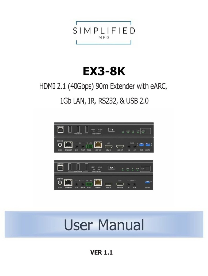
Simplified MFG
Simplified MFG EX3-8K User manual
Simplified MFG
Simplified MFG EX1502K User manual
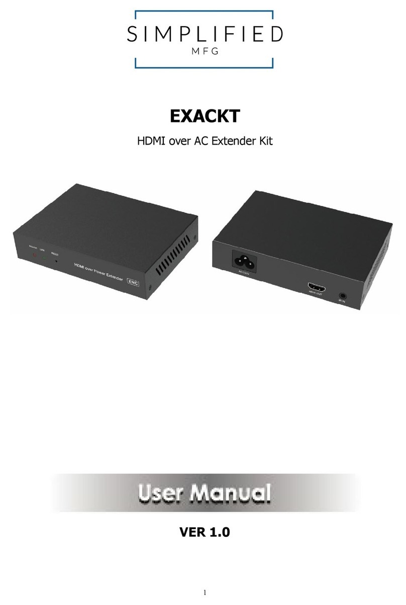
Simplified MFG
Simplified MFG EXACKT User manual
Simplified MFG
Simplified MFG EX2ARC User manual

Simplified MFG
Simplified MFG EXTDA User manual
Simplified MFG
Simplified MFG EX1L User manual
Simplified MFG
Simplified MFG EXARC User manual

Simplified MFG
Simplified MFG ARCEX User manual
Simplified MFG
Simplified MFG EXeARC1 User manual
Simplified MFG
Simplified MFG REX2 User manual

