QUICK REFERENCE GUIDE
PI Catch sensor
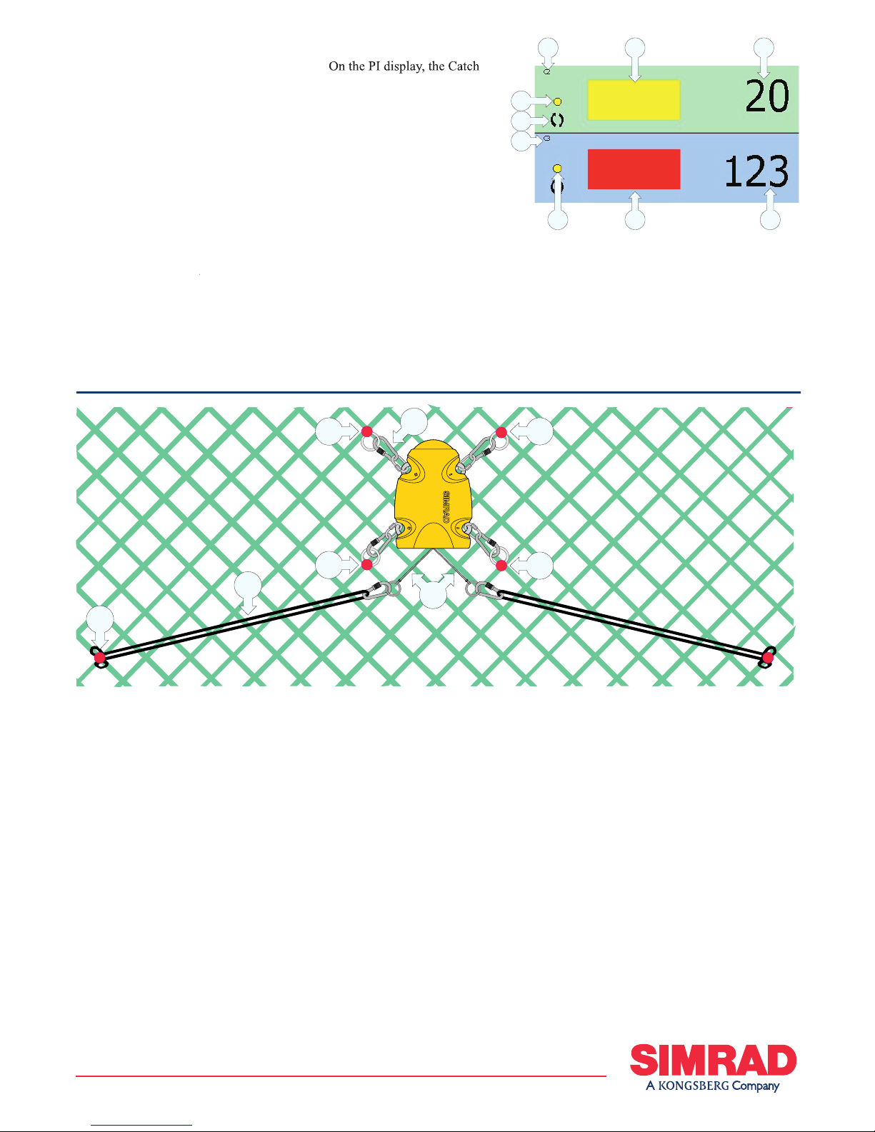
Purpose
trawl has been filled with fish. The sensor
monitors the opening of the meshes in
the cod end, and will be activated once
the volume caught is enough to pull the
Catch sensor principle: Three sensors are mounted at the cod end of the trawl to detect
the amount of fish caught.
To monitor the filling rate, we
recommend that you use minimum two
sensors. The first sensor is located at the
far end of the cod-end indicating that the
trawl is fishing, while the second sensor
tells when to haul. Due to the fish moving
back and forth in the cod-end, the sensor
will normally change status (on/off)
several times until the volume caught
keeps the opening of the meshes stable.
Once installed and put to use, the
sensor will automatically be switched
on once the waterswitch is activated.
After an initial startup, the sensor starts
transmission of the detector wire (F)
status (in or out). When the sensor is not
in use, check that the sensor lamp (D)
is not flashing from time to time, as this
indicaties that the sensor is on and is
discharging its batteries.
If you operate with Fast update rate, the
sensor must be charged approximately
every 35 hours. Used with Normal
or Slow update rates, the operational
life is approximately 150 or 300 hours
respectively. The optimal sensor charging
(A) = Negative charging / fastening lug
(B) = Positive charging / fastening lug
(D) = Location of sensor lamp
(E) = Water switch sensor
temperature is from +10 to +25° C.
Note that charging sensors at sub-zero
temperatures can create explosive gasses.
Simrad AS assumes no liability for the
improper charging of sensors or the use
of chargers not specified in Simrad sensor
On delivery, all Catch sensors are
update rate. If you use more than one
Catch sensor, make sure that you set them
up to operate on different channels and
with different sensor numbers!
Note: The sensor and the PI system
setup must correspond, otherwise the
communication will not work.
To change the sensor setup (channel
selection, update rate etc), use the
Configurator utility.Configurator
The Catch sensor can be configured
(using the PI Configurator software)
will allow the sensor to be used
communication channel on the FS sonar
must be set up to correspond to the
equivalent sensor number (1, 2 3 or 4).
The sensor update rate controls how
often the amount of fish caught is
measured and transmitted to the vessel.
Three settings are available. Note that a
faster update rate will decrease the battery
(~5,3 sec): Recommended for
trawling in areas where the rate of filling
is very high. Use this setting to avoid
damage to the trawl or excessive catches.
(~33 sec): Recommended for
(~125 sec): Recommended if
maximum operational battery life before
charging is required. The system will be
more sensitive to bad communication
conditions due to the slow data update.
When the Catch sensor is configured as
an FA701, it will have a constant update
rate of approximately 64 seconds. This
rate must not be changed.
857-165109 / Rev.A / February 2005
)))
)))
)))
)))
)))
)))
)))
)))
A
A
B
C
B
D
F
(CD11021D)
E