manuals.online logo
Brands
  1. Home
  2. •
  3. Brands
  4. •
  5. Simrad
  6. •
  7. Accessories
  8. •
  9. Simrad PI GEOMETRY - QUICK REFERENCE GUIDE REV B User manual

Simrad PI GEOMETRY - QUICK REFERENCE GUIDE REV B User manual

Quick reference guide
Simrad PI Geometry
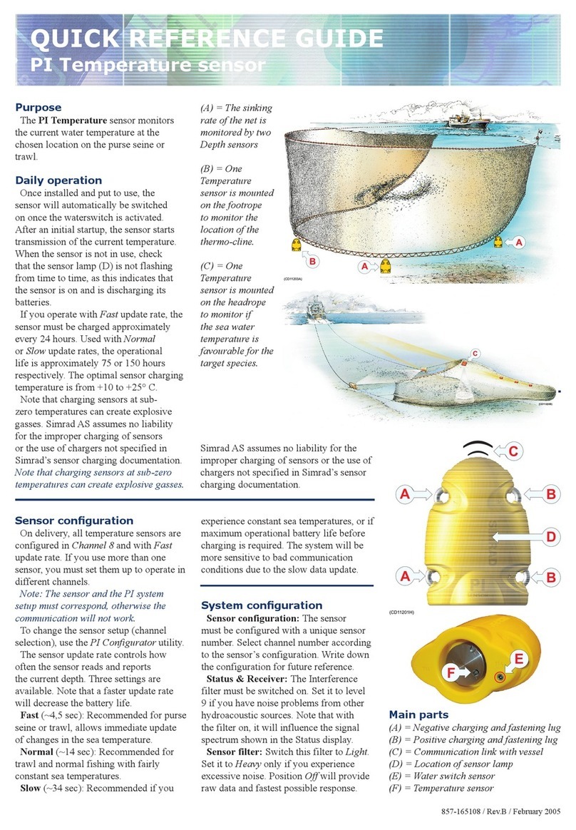
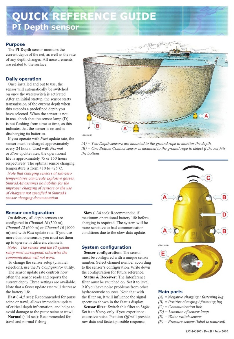
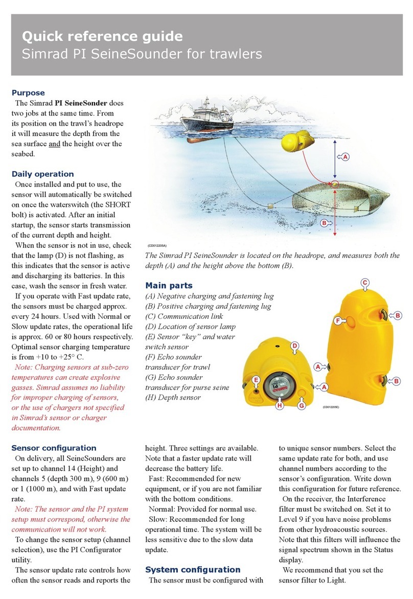
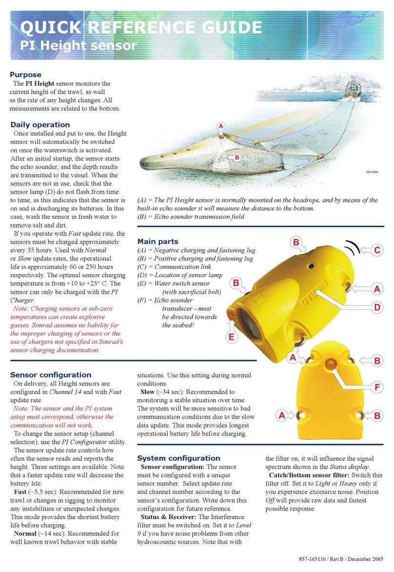
Purpose
The purpose of the Simrad PI
Geometry sensor is to monitor the
geometry of your trawl or danish seine.
This is achieved by making accurate
measurements of the distances from the
centre of the headrope (or footrope) to
each of the trawl doors or wing ends. If
these distances are not identical the trawl
(or danish seine) will be skewed and
unbalanced, and this reduces the catch
efficiency.
In order to carry out the measurements,
the PI Geometry sensor requires two
Mini-R responders, on on each trawl door
(or trawl wing).
Daily operation
Once installed and put to use, the
sensor will automatically be switched
on once the water switch is activated.
After an initial start-up, the sensor starts
transmission of the measured data it
collects.
When the sensor is not in use, check
that the sensor lamp is not flashing, as
this indicates that the sensor is active
and discharging its batteries. In this case,
wash the sensor in fresh water. You can
also apply a thin layer of silicone grease
to the sensor surface to disrupt any
residues of salt that may have built up.
If you operate with Fast update rate, the
sensor must be charged approximately
every 40 hours. Used with Normal update
rate, the operational life is approximately
60 hours. The optimal sensor charging
temperature is from +10 to +25° C.
Note: Charging sensors at sub-zero
temperatures can create explosive
gasses. Simrad assumes no liability for
the improper charging of sensors or the
use of chargers not specified in Simrad’s
sensor charging documentation.
The two rubber inserts provided at
the bottom of each responder adapter
must not be replaced with any other
types or designs. It is essential that these
inserts provide a secure cradle for the
responders, but they must also allow
for free water circulation to allow the
responder’s water switch to engage. Also,
the design of the inserts allows sand and
mud to flow out when the trawl doors are
pulled up from the water.
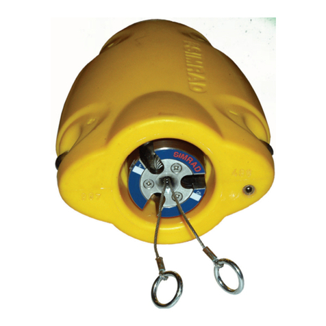
Main items
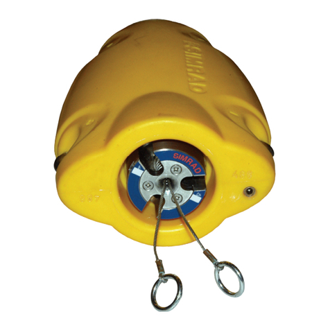
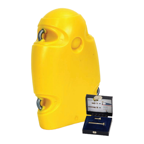
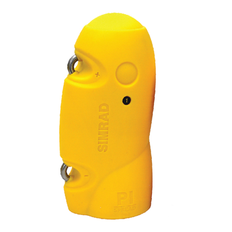
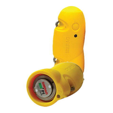
(A) Negative charging & fastening lug
(B) Positive charging & fastening lug
(C) Communication link to the vessel and
to the responders
(D) Geometry set identification
(E) Location of water switch and sensor
identification label
Sensor conguration
On delivery, all PI Geometry sensors are
configured as follows:
Responder: Responder 1
Distance: Channels 1 and 5 / Fast
Note: The sensor and the PI system
setup must correspond, otherwise the
communication will not work.
To change the setup, use the PI
Configurator utility.
The sensor update rate controls how
often the sensor reads and reports the
depth. Three settings are available; Fast,
Normal and Slow. Note that a faster
update rate will decrease the battery life.
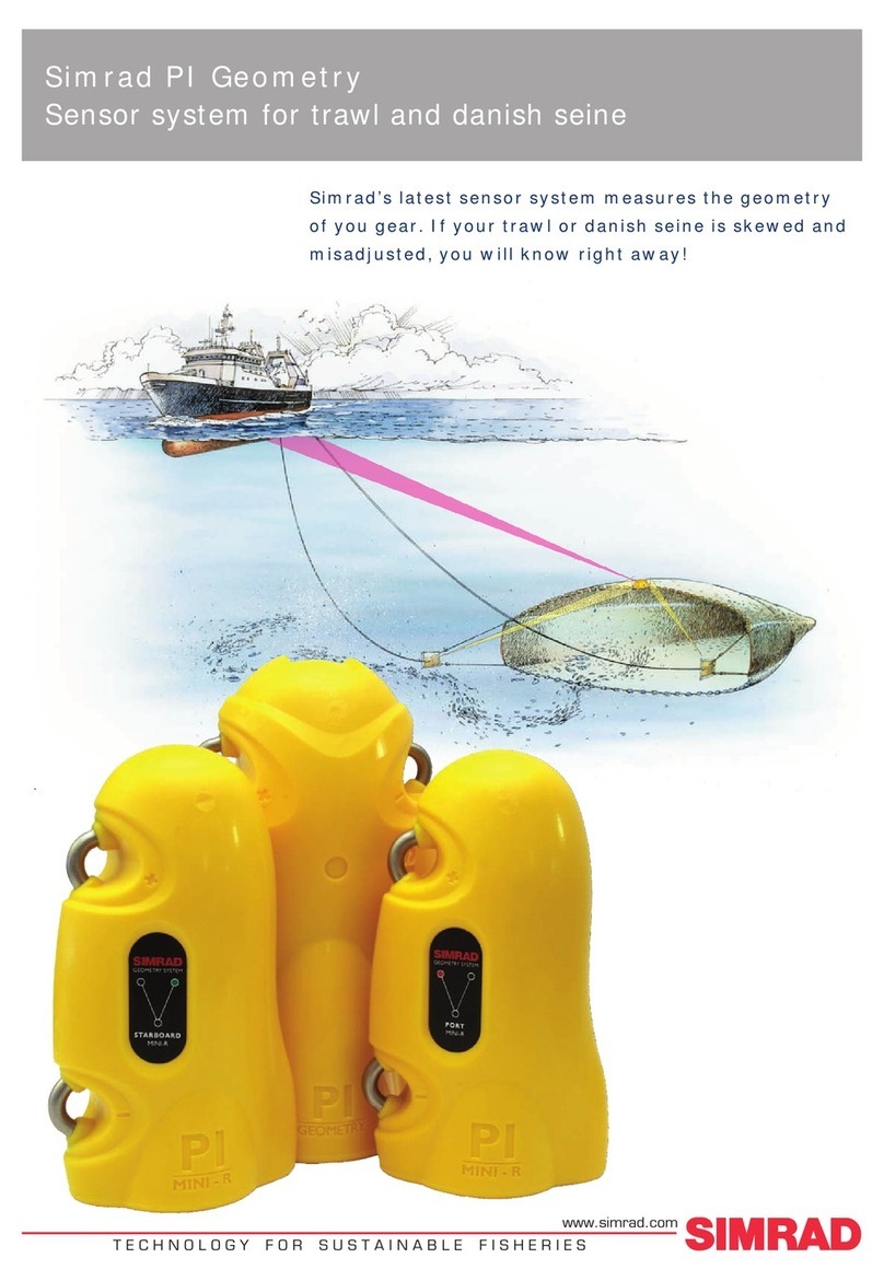
(A) The PI Geometry sensor is mounted at the exact centre of the headrope or footrope.
(B) The two Mini-R responders are mounted on each trawl door or trawl wing.
(C) Each of the two Mini-R responders communicate with the PI Geometry sensor to
measure the distances.
(D) The PI Geometry sensor uses an acoustic link to transmit the results from the
distance measurements to the PI system on the vessel.
322417 / Rev.B / February 2009
Sacricial water switch
The water switch on your sensor is
a sacrificial brass screw. The bolt will
gradually be worn out. Check it from time
to time to remove corrosion, or replace it
if necessary.
Installation
The PI Geometry sensor is mounted at
the exact centre of the trawl or danish
seine opening, either at the headrope at
the top of the opening, or at the footrope
at the bottom. In both locations it must
be mounted with the communication
transducers facing forward. The two
Mini-R responders are normally installed
on the trawl doors or trawl wings. From
this position, they will communicate with
the PI Geometry sensor.
Note: Ensure that you mount the PI
Geometry sensor with the transducer
opening facing forward. There must be a
clear line of sight between the transducer
on the PI Geometry sensor and the
transducers on the Mini-R responders.
The SIMRAD print on the sensor (C) must
point up towards the water surface!
(A) Forward
fastening lugs with
snap hooks and rope
(B) Aft fastening lugs
with snap hooks and
rubber bands
(C) PI Geometry
sensor, top
Kongsberg Maritime AS
Strandpromenaden 50
P. O.Box111
N-3191 Horten,Norway
Simrad
Telephone: +4733034000
Telefax: +4733042987
simrad.sales@simrad.com
www.simrad.com
Numerical presentation
The numerical presentation of the PI
Geometry data is automatically shown
in the relevant display modes. Since this
is a “dual” sensor two yellow rectangles
are used to indicate which two numerical
displays that provide information from the
same sensor.
When the readings are stable, the digits
are shown in black colour. If the contact is
lost, the characters *** are shown in grey.
If the distance is out of range, the display
shows: ???.
(A) Sensor identification
(B) Unit of measurement
(C) Distance
(D) Distance change per minute
(E) Arrows pointing “out” means
that the distance is increasing,
arrows pointing “in” means that
distance is decreasing
(F) Visual alarm
(G) Sensor transmission indicator
(H) Interference warning
(I) Dual sensor identification
1
X1 [m]
143.5

1
X2 [m]
143.5

(CD012221-007)
ABC
I
E
D
F
H
G
1
1
AA
C
B
B
(CD012221-004)
Recommended procedure
1 Assemble a bag of ne-meshed net,
and tie this bag to the trawl at the
middle of the headrope.
2 Place the sensor inside this bag.
3 Secure the two forward fastening
lugs (A) on the sensor using two
snap hooks and rope.
4 Secure the two aft fastening lugs (B)
on the sensor using snap hooks and
strong rubber bands. This mounting
places the sensor in a cradle
supported on all four sides.
5 Ensure that the sensor is properly
mounted. Check that it is not
permitted to move sideways during
the shing operation, as this may
lead to a communication failure.
6 Make sure that you have best
possible free view between the PI
Geometry sensor and the Mini-R
responders on the trawl doors, and
between the sensor and the vessel.
More information
Read the dedicated instruction manual
to learn more about installation, use and
maintenance of the PI Geometry sensor.

Other manuals for PI GEOMETRY - QUICK REFERENCE GUIDE REV B

1

This manual suits for next models

1

Other Simrad Accessories manuals

Simrad PI SEINESOUNDER - REV D User manual

Simrad

Simrad PI SEINESOUNDER - REV D User manual

Simrad PI BOTTOM CONTACT - DATASHEET REV A User manual

Simrad

Simrad PI BOTTOM CONTACT - DATASHEET REV A User manual

Simrad PI32 User manual

Simrad

Simrad PI32 User manual

Simrad MOUNTING RING COMBI-W-38-200 - SCHEMA REV A User manual

Simrad

Simrad MOUNTING RING COMBI-W-38-200 - SCHEMA REV A User manual

Simrad PI SeineSounder User manual

Simrad

Simrad PI SeineSounder User manual

Simrad PI DEPTH - MANUAL 2 User manual

Simrad

Simrad PI DEPTH - MANUAL 2 User manual

Simrad HS50 User manual

Simrad

Simrad HS50 User manual

Simrad PI HEIGHT - DATASHEET REV A User manual

Simrad

Simrad PI HEIGHT - DATASHEET REV A User manual

Simrad PI HEIGHT - QUICK REFERENCE GUIDE REV A User manual

Simrad

Simrad PI HEIGHT - QUICK REFERENCE GUIDE REV A User manual

Simrad PI DEPTH User manual

Simrad

Simrad PI DEPTH User manual

Simrad PI REMOTE - REV A User manual

Simrad

Simrad PI REMOTE - REV A User manual

Simrad PI REMOTE - QUICK REFERENCE GUIDE REV B User manual

Simrad

Simrad PI REMOTE - QUICK REFERENCE GUIDE REV B User manual

Simrad PI GEOMETRY - QUICK REFERENCE GUIDE REV B User manual

Simrad

Simrad PI GEOMETRY - QUICK REFERENCE GUIDE REV B User manual

Simrad PI SeineSounder User manual

Simrad

Simrad PI SeineSounder User manual

Simrad PX MultiSensor User manual

Simrad

Simrad PX MultiSensor User manual

Simrad PI32 User manual

Simrad

Simrad PI32 User manual

Simrad PI CATCH - QUICK REFERENCE GUIDE REV A User manual

Simrad

Simrad PI CATCH - QUICK REFERENCE GUIDE REV A User manual

Simrad PI DEPTH -  GUIDE 2 User manual

Simrad

Simrad PI DEPTH - GUIDE 2 User manual

Simrad PI REMOTE - REV A User manual

Simrad

Simrad PI REMOTE - REV A User manual

Simrad PI SeineSounder User manual

Simrad

Simrad PI SeineSounder User manual

Simrad PI GEOMETRY User manual

Simrad

Simrad PI GEOMETRY User manual

Simrad PI TWIN SPREAD - QUICK REFERENCE GUIDE REV B User manual

Simrad

Simrad PI TWIN SPREAD - QUICK REFERENCE GUIDE REV B User manual

Simrad PI50 -  REV A User manual

Simrad

Simrad PI50 - REV A User manual

Simrad PI CATCH - DATASHEET REV A User manual

Simrad

Simrad PI CATCH - DATASHEET REV A User manual

Popular Accessories manuals by other brands

BEA IS40 user guide

BEA

BEA IS40 user guide

IFM PQ3 Series operating instructions

IFM

IFM PQ3 Series operating instructions

Trust Start-Line ACDB-7000AC Important information

Trust

Trust Start-Line ACDB-7000AC Important information

Perel EDB8 user manual

Perel

Perel EDB8 user manual

turck NI5-EM12-Y1X-H1141 quick start guide

turck

turck NI5-EM12-Y1X-H1141 quick start guide

nedis WIFIP310FWT quick start guide

nedis

nedis WIFIP310FWT quick start guide

Lippert Components Solera owner's manual

Lippert Components

Lippert Components Solera owner's manual

Amcrest SmartHome user manual

Amcrest

Amcrest SmartHome user manual

GBF PL963 Series user manual

GBF

GBF PL963 Series user manual

Hobo S-LIA-M003 manual

Hobo

Hobo S-LIA-M003 manual

Craftsman 944.511572 instruction manual

Craftsman

Craftsman 944.511572 instruction manual

Omron XPECTIA FZ3 user manual

Omron

Omron XPECTIA FZ3 user manual

Balluff BSI R11A0-XB-CX S75G Series user guide

Balluff

Balluff BSI R11A0-XB-CX S75G Series user guide

aci DRN3.1 Installation and operation instructions

aci

aci DRN3.1 Installation and operation instructions

Maxxima MEW-OS100LNW installation instructions

Maxxima

Maxxima MEW-OS100LNW installation instructions

tecan Balance Kit for SAG 285/01 operating manual

tecan

tecan Balance Kit for SAG 285/01 operating manual

RAB Lighting Lightcloud LCSENSE15/D10 instruction manual

RAB Lighting

RAB Lighting Lightcloud LCSENSE15/D10 instruction manual

Axis F7225-RE installation guide

Axis

Axis F7225-RE installation guide

manuals.online logo
manuals.online logoBrands
  • About & Mission
  • Contact us
  • Privacy Policy
  • Terms and Conditions

Copyright 2025 Manuals.Online. All Rights Reserved.