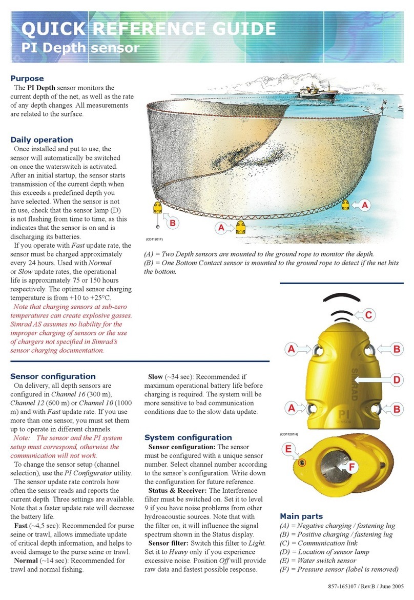
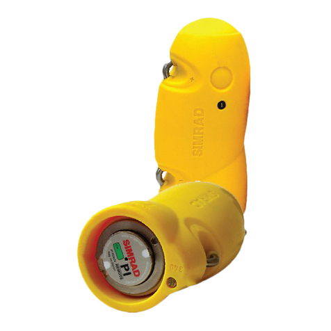
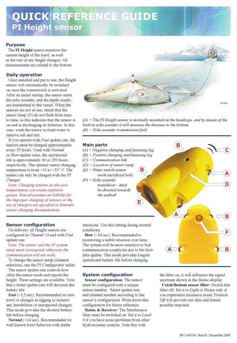
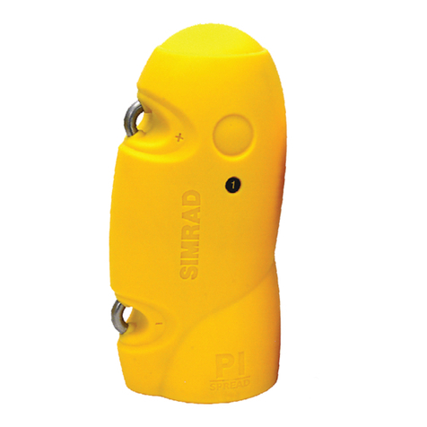
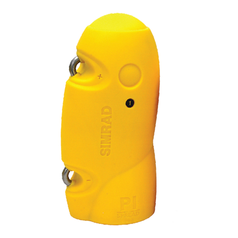
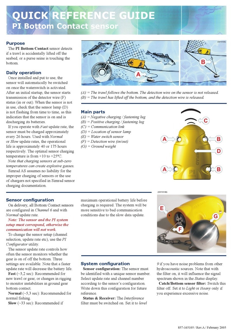
(-) charging/
fastening lug
(+) charging/
fastening lug
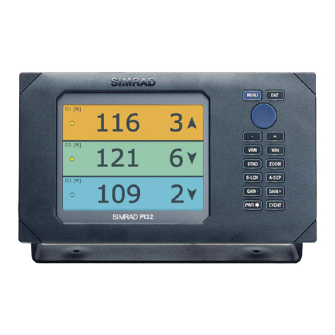
Status display
Installation / Configuration / Receiver parameters
Sensor maintenance, programming and calibration
Charging and testing
Data window information:
-Sensor depth
-Sensor identification
-Units of depth
-Pulse lamp condition
Data window 3Data window 1 Data window 2
SW - software version
E- error message
CH/R - channel number of
the last received sensor.
Hydrophone cable information:
- Black = break
- Red = short circuit
- Yellow = OK
Frequency spectrum - for frequencies on the 00 - 15 band.
Select the desired band by pressing the respective - or +
buttons on the keypad (wait for the unit to update the dis-
play). The graph represents background noise and signal
strength of the frequency band selected.
Information from an in-
terfaced GPS or inte-
grated echo sounder if
the unit is connected to
a transducer.
The Status display shows
sensor data, signal thresholds
and background noise levels
providing an overview of
present hydro-acoustical con-
ditions and the margin for
reliable signal detection.
Other information displayed
includes cable status, pro-
gram version, and echo
sounder / position informa-
tion if the necessary equip-
ment is connected.
Defines sensors 1 to 3
and keeps track of their
attachment locations to
the net.
AGC - recommended to be
ON. Under favorable noise
conditions manual gain ad-
justment may provide in-
creased range.
MP filter - reduces excessive
echo return or interference
from other hydro-acoustic
equipment operating on the
configuredchannel where the
sensor is not in use.
Max shooting speed - com-
pensation for doppler shift
when shooting the net. Maxi-
mum speed may be limited
by channel separation, effec-
tive only when the vessel is
in motion. A low value will
provide a narrower band-
width which is advantageous
under high noise contitions.
Detection threshold - in-
creases the DT if false signals
are detected on a channel
where a sensor is in use. A
high DT indicates that only
the strongest signals will be
received.Alow DT may pro-
vide a longer range under fa-
vorable conditions.
MPFlevel- is activated when
the MP Filter is ON. Reduce
the MPF level value in small
steps to increase the filterís
effectiveness.Avoid reducing
the level so low that the sen-
sorsí signals are also blocked.
Select the channel shown on the sensorsí labels and/or the
visual LED identification signal displayed when turned on.
Note the sensor configuration for later reference. Trawl-
ing: lower sensor channel numbers provide greater range.
Sensor filter:
- OFF = no effect (fastest
update of data).
- Light = average of the
last four pings.
- Heavy = average of the
last eight pings.
The PI30 must receive at least four pings when
first powered up to display data. Should one or
two pings be missing, the predicted value will
be displayed in grey. If the signal is lost, *.* is
displayed.
Calibration - is performed on board the vessel to set the sensorsí reference levels to one meter as follows: Suspend the
sensors over the side of the vessel individually or together at a depth of one meter, the draft plus one meter or the
reference level that is to be defined as one meter. Once the sensorsí depth readings have stabilised, set the Calibration
parameter to YES. Sensor calibration takes one minute and the data will be temporarily displayed as grey during this
time. Once the process is complete, the data will again be displayed in black with updated offset values and a depth
of one meter. Note: Sensors not submerged in saltwater will not be calibrated.
Charging - connect the red and black alligator clamps
to the ì+î and ì-î fastening lugs respectively. Check that
the charging lamp on the charger is illuminated and that
the sensor being charged blinks every four seconds. If it
does not blink (indicating charging mode), the battery
will not be fully charged. Note: Never charge a sensor
withwet rope or chain/wire in contact with the fasten-
ing lugs as the resulting electrolysis will quickly de-
stroy the lugs and the sensor will not be charged.
A fully depleted sensor must be charged for at least 16
hoursto restore itsbatteryto full capacity.Optimalcharg-
ing temperature is from +10∫Cto 25∫C. Never charge sen-
sors at temperatures below freezing.
Warning! The use of chargers not specified by Simrad
may lead to personal injury and/or material damage.
Testing - touch the sea water detector (serial no below
300: touch the cover) and a fastening lug at the same
time. This will cause the sensor to switch ON and
identify the channel it transmits on with a series of blinks
(see the Instruction manual) and begin sending data if it
is not programmed differently.
ï If the sensor does not blink when switched ON, it
indicates a depleted battery and should be charged for a
few minutes and tested again. If it blinks and begins to
send data, it should be charged for at least 16 hours.
ï If the sensor continues to just blink when switched ON
it indicates a close to empty battery. Charge the sensor
for 10 minutes and test. If it resume normal operation,
charge for ~ 16 hours.
ï If the sensor repeats the start up blinking sequence
with a four seconds interval, it indicates fault with the
depth cover. Contact your nearest Simrad dealer.
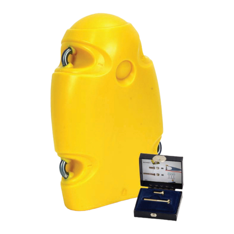
Programming - of sensors is
accomplished using a PC
connectedtotheir charging/
fastening lugs. To program a
sensor both the software,
Simrad number: 889-24037
and a special cable number:
380-204728 are required. The
dealer is normally respon-
sible for programming the
various channel selections
and other functions.
Sensor 1, 2 or 3 Channel 1 to 30
Other depths - if the sensor
is programmed to start at a
depth of 2 m, it should be
suspended at 3 m during the
calibration procedure. Cali-
brate the sensor as described
and note the offset values.
Reduce the offset values by
2 m after calibration.
The red field shows the sig-
nal level that is over the de-
tection threshold, DT.
Thegreen field over thenoise
reference level shows the de-
tection threshold, DT.
Average noise reference lev-
els. Signal to noise ratio -
level difference between red
area in the ìbarî for the chan-
nel and the average level in
the frequency spectrum.
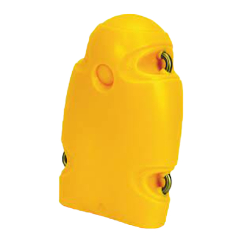
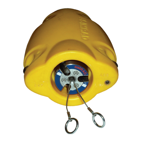
Sea water
detector
Maintenance - sensors are activated when they come into contact with seawater by the electrical connection created
between the saltwater detector and the charging/fastening lug. Rinse sensors with freshwater to avoid leaving a
saltwater film on their exteriors. Such a film can also complete the circuit inadvertently activating a sensor and
depleting its battery when stowed.
Configure sensors with sev-
eral channel intervals to
avoid interference from
strong signals.
Battery capacity -
Depth: ~30 hours
Bottom normal: ~ 60 hours
Catch slow: ~ 2 to 3 weeks
