manuals.online logo
Brands
  1. Home
  2. •
  3. Brands
  4. •
  5. Simrad
  6. •
  7. Accessories
  8. •
  9. Simrad PI32 User manual

Simrad PI32 User manual

PI32 Sensor mounting instructions
(857-164547B)
PI32 Monitoring system for trawls and purses
The system below is configured for use with trawls and purse seines. It may
also be employed with Danish purses, pelagic trawls or other types of gear that
require depth, temperature, bottom contact and catch monitoring.
Configuration -
of sensors attached to towed gear should be toward the mother
vessel. Coverage is optimized when the tops of the sensors are oriented toward
the hydrophone mounted on the vessel’s hull.
Catch sensor -
will normally change status until the quantity of fish caught
is reasonably large. Once the cod-end fills, its natural tendendcy to become “pear
shaped” may cause the catch sensor furthest aft to tilt downwards temporarily
losing or generating unstable communication. This phenomenon is often
experienced just before the next proceeding catch sensor is activated.
Mounting -
and protection of sensors is very important. Sensors attached to
head- or footropes are best protected when sewn in bags designed for that
purpose. Sensors attached to trawling gear should be firmly secured at their
forward ends and drawn aft so that they lay horizontally when towed. Sensors
attached to towed purse seining gear should be allowed to hang as freely as
possible and point vertically when pursing.
Complete overview -
of the fishing operation is achieved with three sensors
marked correspondingly with D1, D2 or D3 and attached to the purse seine as
illustrated. Make sure that the attachment locations chosen will not subject the
sensor to unnecessary abuse when shooting. Precautions should also be taken
when sensors pass through the powerblock.
Tuna purse -
attach sen-
sors to the footwire, refer
to the Instruction manual
for details.
D3
D1
D2
Purse seine
Depth sensor
Temperature sensor
Depth sensor
Bottom sensor
Catch sensors
Monitoring
- sensors are preferably attached to the purse
wire with a purse ring or alternatively, as show here, to
the bridle. Sensors must be allowed to hang as freely as
possible so that they point vertically when pursing.
Sensors can be attached to the headwire to warn if it
is pulled under the surface when pursing.
Bottom sensors -
are attached to the purse wire using a
purse ring, wire strop and two karabiners. A weight of
approximately 4.5 kg (or another purse ring) is attached
to the sensors’ detector wire with a flexible, thin rope. The
total length of the strop, sensor, detector wire and rope
determined the distance monitored to the bottom.
Shooting -
thread the weight on the ring needle (but not
around the purse wire) so that the bottom sensor will
be deployed first. The weight must hang freely and sink
clear of other gear so that it may activate the sensor when
bottom contact is made.
Weight
Detector
wire
Rope
Strop
Karabiner
Purse
ring
Bottom sensor attachment
Catch sensor attachment
1.) Locate the middle of the footrope and bend the attachment ring for the stay to the “bottom” and two
strops attached to karabiners on either side to its “top”. The strops should create a bridle about 15 to 20
cm in length that will securely hold the bottom sensor in a stable position.
2.) Bend the penetration ring for the detection wire about 30 cm below the footrope as illustrated. Attach
the bottom sensor and check that its detection wire passes through the centre of the penetration ring.
Remove the netting on the inside of the penetration ring.
3.) Attach the rubber strops so that the bottom sensor is held horizontally when towed.
IMPORTANT: Carefully attach the sensor to the inside of the trawl so that it is not subject to damage or
torn off during fishing operations. The sensor’s detection wire must always be allowed to pass freely
through the centre of the penetration ring when it is deployed.
Contact -
bottom sensors can detect bottom contact with a
precision of just a few centimeters when correct stay and
detection chain lengths are used. Optimal sensor perfor-
mance requires that these lengths are configured with regard
to both each other and the gear in use (the standard delivery includes a 63 cm stay and 39 cm detection chain
for use with 14 to 16 inch bobbins or rock hoppers).
Configuration -
the desired bottom detection distance is relative to the diameter of the rock hoppers,
bobbins or other gear in use. This relationship can be determined and precise stay and detection chain
length adjustments made as described below.
Setup
- lay the bottom sensor on an elevated surface and observe detection wire movement while simulating
bottom contact by raising the weight. Adjust the detection chain length as necessary. Tilt the weight
approximately 25°(
α
is due to drag through the water) opposite the towed direction and adjust the stay
length so that it begins to be taught. Avoid extra links at the weight ends when shorting chains.
IMPORTANT: Weights must be removed from a bottom sensors with a long stays and detection chains
before they transit the drum when hauling to prevent damage.
Location -
attach the sensor at the top of the cod-end, closest to where
the catch is to be monitored. As the cod-end fills the net’s mesh will
become taught and activate the catch sensor.
Attachment -
the catch sensor’s orientation toward the mother vessel is
maintained by the steel/nylon attachment rings, strops and karabiners
bent to the net. The number of mesh squares the sensor is supported
between must be restricted to avaoid unnecessary stress on the gear
when the net is filled to maximum capacity. Note that both steel
attachment rings must be located on the same side of the sensor.
Sensitivity -
is determined by the number of mesh squares separating
the two rubber strops (a larger number increases sensitivity, a smaller
reduces it). Simulate sensor activation by stretching the net’s mesh to
approximate the load generated by a full catch. Experiment accordingly
to determine the correct attachment points and then permanently
mark their locations for future reference.
Rubber strops -
are subject to heavy loading/wear; they should be
changed at regular intervals and checked before shooting. Strops with
cracks or visible signs of damage should be change immediately.
Sensor attachment -
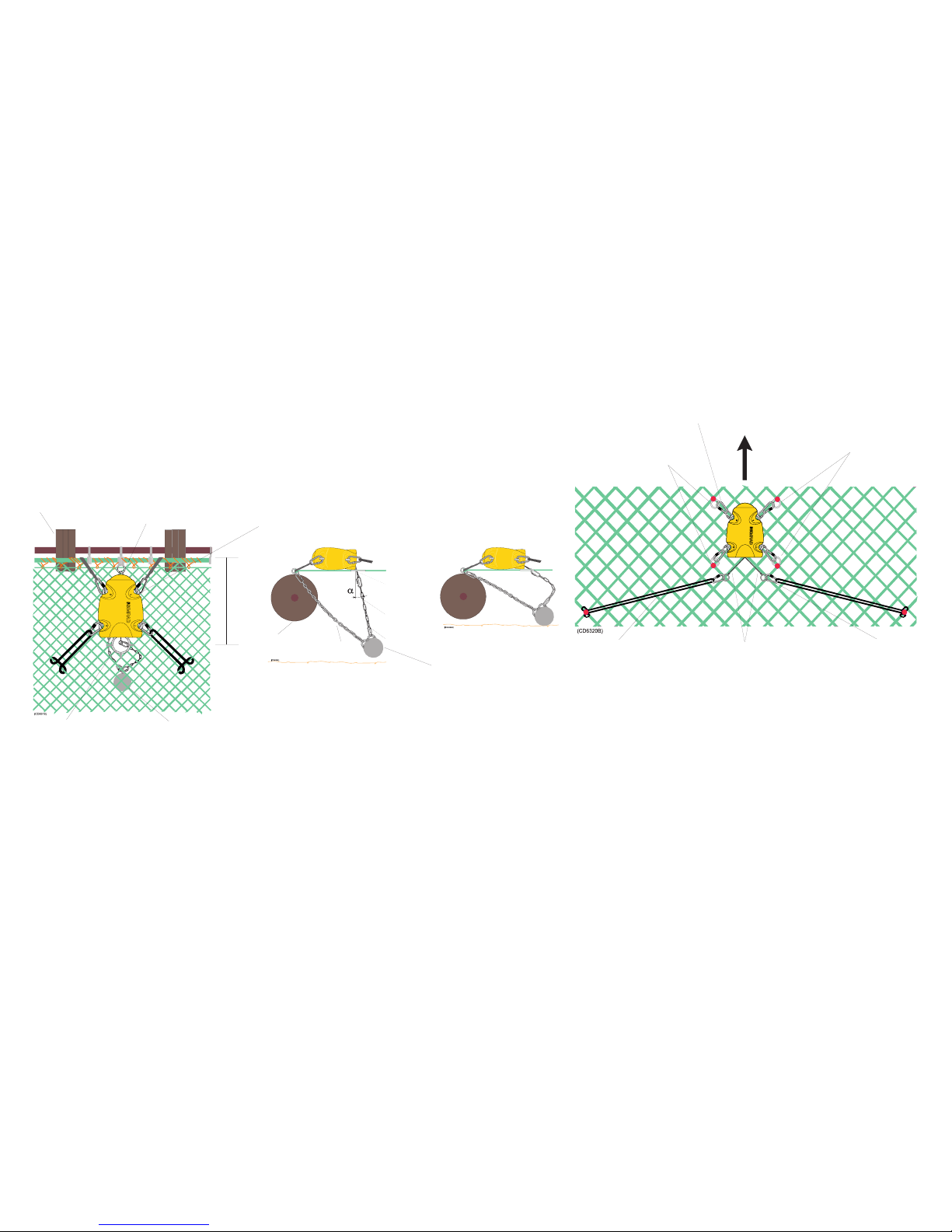
to a net with an approximate mesh size of 140
mm is illustrated below. The distance between the anchor points for
the attachment rings and rubber strops will vary according to mesh
size and sensitivity required.
Vessel
Karibiner and
screw link
Nylon
attachment rings,
bent to the netting
Steel
attachment rings,
bent to the netting
Rubber strop
Karabiner
Detector wires
bent to the netting
bent to the netting
bent to the netting
Rock hopper,
bobbins, etc.
Attachment ring for the
stay bent securely to the
“bottom”of the footrope.
Karabiners are bent securely to the “top” of the footrope. If the bottom sensor is
attached to the wings, the length of the lashings must be adjusted so that the sensor
points toward the mother vessel when towed.
Penetration ring for
the detection wire.
Weight and stay hang
freely under the trawl.
Touch Down
Detection
wire
Detection
chain
Weight
Lift Off
Stay
Rock hopper
30 cm
Bottom
End link
Note 1
Note 1
Note 1:
The stay can also be attached to the steel spacer between the bobbins/rock
hopper if the footrope is held fairly stable relative to the gear.

Other manuals for PI32

5

This manual suits for next models

1

Other Simrad Accessories manuals

Simrad PI CATCH - QUICK REFERENCE GUIDE REV A User manual

Simrad

Simrad PI CATCH - QUICK REFERENCE GUIDE REV A User manual

Simrad PI DEPTH - MANUAL 2 User manual

Simrad

Simrad PI DEPTH - MANUAL 2 User manual

Simrad PI TWIN SPREAD - QUICK REFERENCE GUIDE REV B User manual

Simrad

Simrad PI TWIN SPREAD - QUICK REFERENCE GUIDE REV B User manual

Simrad PI CATCH - DATASHEET REV A User manual

Simrad

Simrad PI CATCH - DATASHEET REV A User manual

Simrad PI GEOMETRY - QUICK REFERENCE GUIDE REV B User manual

Simrad

Simrad PI GEOMETRY - QUICK REFERENCE GUIDE REV B User manual

Simrad PI BOTTOM CONTACT - QUICK REFERENCE GUIDE REV... User manual

Simrad

Simrad PI BOTTOM CONTACT - QUICK REFERENCE GUIDE REV... User manual

Simrad PI SeineSounder User manual

Simrad

Simrad PI SeineSounder User manual

Simrad PI DEPTH -  GUIDE 2 User manual

Simrad

Simrad PI DEPTH - GUIDE 2 User manual

Simrad PI TEMPERATURE - QUICK REFERENCE GUIDE REV B User manual

Simrad

Simrad PI TEMPERATURE - QUICK REFERENCE GUIDE REV B User manual

Simrad PI SeineSounder User manual

Simrad

Simrad PI SeineSounder User manual

Simrad PI50 -  REV A User manual

Simrad

Simrad PI50 - REV A User manual

Simrad MOUNTING RING COMBI-W-38-200 - SCHEMA REV A User manual

Simrad

Simrad MOUNTING RING COMBI-W-38-200 - SCHEMA REV A User manual

Simrad PI GEOMETRY - QUICK REFERENCE GUIDE REV B User manual

Simrad

Simrad PI GEOMETRY - QUICK REFERENCE GUIDE REV B User manual

Simrad PI GEOMETRY User manual

Simrad

Simrad PI GEOMETRY User manual

Simrad PI REMOTE - REV A User manual

Simrad

Simrad PI REMOTE - REV A User manual

Simrad HS50 User manual

Simrad

Simrad HS50 User manual

Simrad PI32 User manual

Simrad

Simrad PI32 User manual

Simrad PI DEPTH User manual

Simrad

Simrad PI DEPTH User manual

Simrad PI REMOTE - QUICK REFERENCE GUIDE REV B User manual

Simrad

Simrad PI REMOTE - QUICK REFERENCE GUIDE REV B User manual

Simrad PI HEIGHT - QUICK REFERENCE GUIDE REV A User manual

Simrad

Simrad PI HEIGHT - QUICK REFERENCE GUIDE REV A User manual

Simrad PI HEIGHT - DATASHEET REV A User manual

Simrad

Simrad PI HEIGHT - DATASHEET REV A User manual

Simrad PI REMOTE - REV A User manual

Simrad

Simrad PI REMOTE - REV A User manual

Simrad PI DEPTH User manual

Simrad

Simrad PI DEPTH User manual

Simrad PI32 User manual

Simrad

Simrad PI32 User manual

Popular Accessories manuals by other brands

Lindo LVD01 user manual

Lindo

Lindo LVD01 user manual

PCB Piezotronics 109C11 Installation and operating manual

PCB Piezotronics

PCB Piezotronics 109C11 Installation and operating manual

Panasonic WX-LA20 manual

Panasonic

Panasonic WX-LA20 manual

Marathon MBWC24 Owner's use and care guide

Marathon

Marathon MBWC24 Owner's use and care guide

General Awnings AC1000 Assembly instructions

General Awnings

General Awnings AC1000 Assembly instructions

Skov DA 150B Technical user guide

Skov

Skov DA 150B Technical user guide

Panasonic AG-BS300P operating instructions

Panasonic

Panasonic AG-BS300P operating instructions

RS Barcelona You and Me 220 user manual

RS Barcelona

RS Barcelona You and Me 220 user manual

UNITED OFFICE KH 4444 LASER POINTER Safety instructions

UNITED OFFICE

UNITED OFFICE KH 4444 LASER POINTER Safety instructions

Cerlic ITX 20 manual

Cerlic

Cerlic ITX 20 manual

Baumer UNAM 18P7903/S14 manual

Baumer

Baumer UNAM 18P7903/S14 manual

Life Giving Warmth The Cozee user manual

Life Giving Warmth

Life Giving Warmth The Cozee user manual

Elkay EZOTL Series Installation, care & use manual

Elkay

Elkay EZOTL Series Installation, care & use manual

EnOcean STM 350 user manual

EnOcean

EnOcean STM 350 user manual

Marathon BA030068-RS-EU1 quick start guide

Marathon

Marathon BA030068-RS-EU1 quick start guide

Triner Scale TS-700 Series Calibration Instruction

Triner Scale

Triner Scale TS-700 Series Calibration Instruction

Dacor Flushing System Kit ACFS Installation and user instructions

Dacor

Dacor Flushing System Kit ACFS Installation and user instructions

Steinberg UR-RT4 Startup guide

Steinberg

Steinberg UR-RT4 Startup guide

manuals.online logo
manuals.online logoBrands
  • About & Mission
  • Contact us
  • Privacy Policy
  • Terms and Conditions

Copyright 2025 Manuals.Online. All Rights Reserved.