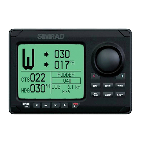
Simrad Robertson AP9 Mk3 User manual

INSTRUCTION MANUAL
Robertson AP9 Mk3
Autopilot
20169223

Simrad Robertson AS Telephone: +47 51 46 20 00
Nyåskaien Telefax: +47 51 46 20 01
P.O. Box 55
N-4379 Egersund, Norway
NOTE!
Simrad Robertson AS makes every effort to ensure that the information contained
within this document is correct. However, our equipment is continuously being
improved and updated, so we cannot assume liability for any errors which may
occur.
The information contained within this document remains the sole property of Simrad
Robertson AS. No part of this document may be copied or reproduced in any form or
by any means, and the information contained within is not to be passed on to a third
party, without the prior written consent of Simrad Robertson AS.
Warning
The equipment to which this manual applies must only be used for the purpose for
which it was designed. Improper use or maintenance may cause damage to the
equipment or injury to personnel. The user must be familiar with the contents of
the appropriate manuals before attempting to operate or work on the equipment.
Simrad Robertson AS disclaims any responsibility for damage or injury caused by
improper installation, use or maintenance of the equipment.

Instruction Manual
20169223D I
Instruction Manual
The manual is intended as a reference guide for operating
and correctly installing the AP9 Mk3 Autopilot.
Great care has been paid to simplify operation and set-up.
However, an autopilot is a complex electronic system; it is
affected by sea conditions, speed of the vessel, hull shape
and size.
Please take time to read this manual to get a thorough
understanding of the operation and system components
and their relationship to a complete autopilot system.
Other documentation materials that is provided with your
system include a warranty card. This must be filled in by
the authorized dealer that performed the installation and
mailed in to activate the warranty.

Robertson AP9 Mk3 Autopilot
II 20169223D
Document revisions
Documentation
department Hardware/Software
design Project/Product
Management
Rev Date Sign Date Sign Date Sign
– 10.04.96 N.G. 10.04.96 G.K. 10.04.96 Th.H.
A 30.05.96 N.G. 30.05.96 G.K. 30.05.96 Th.H.
B 12.07.96 N.G. 12.07.96 T.J. 12.07.96 Th.H.
C 3.9.99 N.G. 3.9.99 T.J. 3.9.99 Th.H.
D 07.11.00 N.G. 07.11.00 T.J. 07.11.00 T.R.
Document history
Rev. – First edition
Rev. A Updated table of contents and references throughout the manual
Rev. B Minor corrections in table page 1-6 and fig. 1-5. New dimensional
drawing of control unit, fig. 4.1. Section 5: Due to modified PCBs the
instructions for ferrite core mounting are omitted. New component
layout and set-up procedure for Dual Analogue Board included. Section
8: Updated circuit diagrams included. Section 9: Certificate of Type
Approval included.
Rev. C New layout. Section 2 and 5 revised according to new software version
V1R3. Diagrams updated. Dimensional drawing of RF Standard
Transmission link included. D9X Bus cable connection included. Index
and distributor list included.
Rev. C has not been released.
Rev. D Updated according to software version V1R4.

Instruction Manual
20169223D III
TABLE OF CONTENTS
1 INTRODUCTION .........................................................................................................1-1
1.1 General .........................................................................................................1-1
1.2 MK3 System Layout............................................................................................1-1
1.3 Options available with the standard system ..................................................1-1
1.4 AP9 MK3 Standard System, On-Off Valves....................................................1-3
1.5 AP9 MK3 Standard System, Dual analogue output ......................................1-4
1.6 AP9 MK3 with analogue thruster control.......................................................1-5
1.7 Combinations of Heading Sensors...................................................................1-6
GYRO COMPASS................................................................................................1-6
FLUXGATE COMPASS......................................................................................1-8
1.8 Dual Station .........................................................................................................1-9
SERIAL LINES.....................................................................................................1-9
1.9 Connection of steering levers..........................................................................1-11
1.10 Rudder Angle Indicators .................................................................................1-12
1.11 Special Applications.........................................................................................1-13
2 OPERATION .........................................................................................................2-1
2.1 General .........................................................................................................2-1
2.2 Front Panel .........................................................................................................2-1
2.3 Mode selection.....................................................................................................2-2
HELMSMAN (Power ON).................................................................................2-2
AUTOPILOT........................................................................................................2-2
NAV. MODE........................................................................................................2-2
OFF........................................................................................................................2-2
ALARM ................................................................................................................2-3
Thruster/rudder parameters.............................................................................2-3
2.4 Parameter setting ................................................................................................2-3
General..................................................................................................................2-3
Switch ON............................................................................................................2-4
HELMSMAN.......................................................................................................2-5
AUTOPILOT........................................................................................................2-5
INCREASE- and DECREASE-buttons.............................................................2-5
ILLUM ..................................................................................................................2-5
COMPASS SELECT ............................................................................................2-6
RUDDER ..............................................................................................................2-6
WEATHER...........................................................................................................2-7
COUNTER RUDDER..........................................................................................2-8
INFO .....................................................................................................................2-9
2.5 Course selection ................................................................................................2-15
2.6 Navigational steering.......................................................................................2-15

Robertson AP9 Mk3 Autopilot
IV 20169223D
General................................................................................................................2-15
Steering by XTE to waypoint...........................................................................2-16
Priority mode (APB sentence).........................................................................2-18
Ecdis mode ( APB sentence)............................................................................2-19
Remote Control .................................................................................................2-19
AP9 MK3 Dual Station.....................................................................................2-20
F200-40 Remote Control...................................................................................2-21
S9 Steering Lever (NFU) ..................................................................................2-22
FOLLOW-UP Steering Levers.........................................................................2-23
2.7 Fault Warnings..................................................................................................2-25
HEADING SENSOR WARNINGS.................................................................2-25
OTHER FAULT WARNINGS.........................................................................2-28
3 DESIGN AND THEORY OF OPERATION..............................................................3-1
3.1 General system description...............................................................................3-1
3.2 AP9 MK3 Control Unit.......................................................................................3-2
3.3 CD109 Course Detector......................................................................................3-4
CD109 Course Detector Principle.....................................................................3-4
3.4 Course Handling.................................................................................................3-4
3.5 RF14XU Rudder Feedback Unit........................................................................3-6
3.6 D90 Series Distribution Unit .............................................................................3-7
POWER SUPPLY BOARD.................................................................................3-7
INTERCONNECTION BOARD........................................................................3-8
THRUSTER INTERFACE BOARD...................................................................3-9
SOLID STATE BOARD ....................................................................................3-10
DUAL ANALOGUE PCB ................................................................................3-13
3.7 F200-40 Remote Control...................................................................................3-15
3.8 FU91/92 Follow-Up Lever ..............................................................................3-16
4 TECHNICAL SPECIFICATIONS ...............................................................................4-1
4.1 AP9 MK3 Control Unit.......................................................................................4-1
4.2 AP9 MK3 Gyro Interface Board........................................................................4-2
4.3 CD109 Course Detector......................................................................................4-2
4.4 RFC35R Rate Compass.......................................................................................4-3
4.5 RFC35NS Fluxgate Compass.............................................................................4-4
4.6 RFC35N NMEA Compass..................................................................................4-4
4.7 Distribution Unit.................................................................................................4-5
4.8 RF14XU Rudder Feedback Unit........................................................................4-7
4.9 RF Standard Transmission Link .......................................................................4-8
4.10 S9 Steering Lever.................................................................................................4-8
4.11 FU91 Steering Lever............................................................................................4-9
4.12 S35 Steering Lever.............................................................................................4-10

Instruction Manual
20169223D V
4.13 F1/2 Remote Control........................................................................................4-11
4.14 F200-40 Remote Control...................................................................................4-11
4.15 RI9 Rudder Angle Indicator............................................................................4-12
4.16 IP protection ...................................................................................................4-13
4.17 Specification of messages.................................................................................4-14
CTS steering.......................................................................................................4-14
Bearing steering.................................................................................................4-14
Priority (mixed) steering..................................................................................4-14
Speed correction signal (VTG) ........................................................................4-14
5 INSTALLATION .........................................................................................................5-1
5.1 Unpacking and handling...................................................................................5-1
5.2 General .........................................................................................................5-1
5.3 Control Unit.........................................................................................................5-1
Connector assembly............................................................................................5-2
Screen termination..............................................................................................5-3
5.4 Heading sensors..................................................................................................5-4
General..................................................................................................................5-4
Magnetic compass...............................................................................................5-4
Gyro Compass.....................................................................................................5-7
RFC35NS Fluxgate Compass...........................................................................5-10
RFC35N NMEA Compass................................................................................5-12
5.5 D90/D91/D92/D93/D99 Distribution Unit.................................................5-12
Mounting............................................................................................................5-13
Electrical connections.......................................................................................5-13
Adjustments.......................................................................................................5-15
5.6 RF14XU Rudder Feedback Unit......................................................................5-15
Mechanical mounting.......................................................................................5-15
Electrical installation ........................................................................................5-16
Scaling of rudder angle....................................................................................5-17
Final check..........................................................................................................5-19
5.7 Optional equipment..........................................................................................5-19
AP9 MK3 Dual Station.....................................................................................5-19
5.8 Mode selection (External mode selector).......................................................5-21
F200-40 and Mode Selection............................................................................5-22
Complete Mode Selections ..............................................................................5-22
5.9 F200-40 Remote Control...................................................................................5-23
5.10 S9 Steering Lever...............................................................................................5-23
Mounting............................................................................................................5-23
Electrical connection.........................................................................................5-24
Function..............................................................................................................5-24
5.11 FU9X Follow up Steering Lever......................................................................5-26

Robertson AP9 Mk3 Autopilot
VI 20169223D
Mounting............................................................................................................5-26
Electrical connection.........................................................................................5-26
5.12 S35 connection to D9X......................................................................................5-27
S35 alternative connection...............................................................................5-27
5.13 RI9 Rudder Angle Indicator............................................................................5-28
5.14 PANORAMA Mk2 Rudder Angle Indicator ................................................5-28
Installation .........................................................................................................5-28
5.15 Analogue ±10V or 4-20mA control signals...................................................5-29
5.16 Connection to Navigational Receiver ............................................................5-31
5.17 Start-Up and commissioning...........................................................................5-32
Power ON...........................................................................................................5-32
Rudder Feedback Unit Adjustments..............................................................5-32
5.18 Selection of parameter settings .......................................................................5-33
Information and Debug Loops........................................................................5-33
5.19 Dockside Alignment/test................................................................................5-49
General................................................................................................................5-49
RF14XU Feedback unit (ON-OFF valves)......................................................5-49
Rudder Angle Indicators .................................................................................5-50
Analogue signal, Rudder & Thruster.............................................................5-50
Deflection test (Rudder or azimuth thruster propulsion)...........................5-52
Tunnel Thruster function.................................................................................5-57
Gyro Compass selection...................................................................................5-58
Magnetic Compass (CD109) adjustments .....................................................5-60
FOLLOW-UP Levers ........................................................................................5-61
Dual Station Configuration .............................................................................5-61
Mode selectors...................................................................................................5-61
5.20 Sea Trial ...................................................................................................5-62
RFC35NS Fluxgate Compass calibration and alignment............................5-64
RFC35N NMEA and RFC35R Compass calibration and alignment..........5-65
On course steering ............................................................................................5-66
Minimum rudder function ..............................................................................5-66
Course Changes.................................................................................................5-67
Save Parameters ................................................................................................5-69
Navigational Steering test................................................................................5-71
Special feedback arrangement ........................................................................5-72
6 TROUBLE SHOOTING................................................................................................6-1
6.1 Fault warnings.....................................................................................................6-1
6.2 CD109 COURSE DETECTOR............................................................................6-4
6.3 FLUXGATE COMPASS......................................................................................6-4
6.4 MALFUNCTION OF THE D90-91-92..............................................................6-4
6.5 MALFUNCTION OF THE D93/D94 ...............................................................6-5

Instruction Manual
20169223D VII
6.6 THRUSTER INTERFACE PCB..........................................................................6-5
7 SPARE PARTS .........................................................................................................7-1
7.1 AP9 MK3 Control Unit.......................................................................................7-1
7.2 Distribution Unit.................................................................................................7-1
7.3 CD109 Course Detector......................................................................................7-3
7.4 RF14XU Rudder Feedback Unit........................................................................7-4
7.5 RF Standard Transmission link.........................................................................7-5
7.6 F200-40 Remote Control.....................................................................................7-6
7.7 S9 Steering Lever.................................................................................................7-7
7.8 FU91 Steering Lever............................................................................................7-7
7.9 S35 NFU Steering Lever.....................................................................................7-7
8 Drawings ........................................................................................................................8-1
9 Index ...............................................................................................................................9-1
10 Appendix ...................................................................................................................10-1
Approvals
Sales and service worldwide (000929)
TABLE OF FIGURES
FIG. 1-1 AP9 MK3 SYSTEM LAYOUT..................................................................... 1-2
FIG. 1-4 THRUSTER CONTROL................................................................................ 1-5
FIG. 1-5 HEADING SENSORS .................................................................................. 1-7
FIG. 1-6 SERIAL LINE CONNECTIONS..................................................................... 1-9
FIG. 1-7 DUAL STATION SYSTEM ......................................................................... 1-10
FIG. 1-8 NFU/FU LEVERS................................................................................... 1-11
FIG. 1-9 RUDDER ANGLE INDICATORS................................................................ 1-12
FIG. 1-10 SPECIAL APPLICATIONS, EXAMPLE 1................................................... 1-13
FIG. 1-11 SPECIAL APPLICATIONS, EXAMPLE 2................................................... 1-14
FIG. 1-12 SPECIAL APPLICATION, EXAMPLE 3..................................................... 1-15
FIG. 2-1 AP9 MK3 FRONT PANEL......................................................................... 2-1
FIG. 2-2 RUDDER SETTINGS.................................................................................... 2-7
FIG. 3-1 AUTOPILOT PRINCIPLE DIAGRAM ............................................................ 3-1
FIG. 3-2 PROCESSOR CONTROLLED AUTOPILOT.................................................... 3-2
FIG. 3-3 AP9 MK3 ELECTRONIC BOARDS............................................................. 3-3
FIG. 3-4 COURSE DETECTOR PRINCIPLE ................................................................ 3-4
FIG. 3-5 AP9 MK3 COURSE HANDLING............................................................... 3-5
FIG. 3-6 RF14XU PRINCIPLE.................................................................................. 3-6
FIG. 3-7 D9X PCBS................................................................................................ 3-7
FIG. 3-8 POWER SUPPLY PCB - SIMPLIFIED DIAGRAM .......................................... 3-8
FIG. 3-9 INTERCONNECTION PCB - SIMPLIFIED DIAGRAM................................... 3-8
FIG. 3-10 THRUSTER INTERFACE PCB - SIMPLIFIED DIAGRAM ............................ 3-9
FIG. 3-11 SOLID STATE PCB - SIMPLIFIED DIAGRAM .......................................... 3-10
FIG. 3-12 SOLID STATE PCB - CONNECTION OF LIMIT SWITCHES....................... 3-12
FIG. 3-13 SOLID STATE PCB - CONNECTION OF SOLENOIDS............................... 3-12
FIG. 3-14 DUAL ANALOGUE PCB - SIMPLIFIED DIAGRAM................................. 3-14
FIG. 3-15 F200-40 SIMPLIFIED DIAGRAM ............................................................ 3-15

Robertson AP9 Mk3 Autopilot
VIII 20169223D
FIG. 3-16 FU91/92 SIMPLIFIED DIAGRAM .......................................................... 3-16
FIG. 4-1 AP9 MK3 CONTROL UNIT, DIMENSIONS .............................................. 4-1
FIG. 4-2 CD109 COURSE DETECTOR, DIMENSIONS .............................................. 4-2
FIG. 4-3 RFC35R RATE COMPASS, DIMENSIONS................................................. 4-3
FIG. 4-4 D9X DISTRIBUTION UNIT, DIMENSIONS................................................. 4-6
FIG. 4-5 RF14XU RUDDER FEEDBACK UNIT DIMENSIONS .................................. 4-7
FIG. 4-6 RF STANDARD TRANSMISSION LINK - DIMENSIONS............................... 4-8
FIG. 4-7 S9 STEERING LEVER - DIMENSIONS......................................................... 4-8
FIG. 4-8 FU91 STEERING LEVER - DIMENSIONS.................................................... 4-9
FIG. 4-9 S35 STEERING LEVER - DIMENSIONS..................................................... 4-10
FIG. 4-10 F1/2 REMOTE CONTROL - DIMENSIONS............................................. 4-11
FIG. 4-11 F200-40 REMOTE CONTROL DIMENSIONS ........................................... 4-11
FIG. 4-12 RI9 RUDDER ANGLE INDICATOR - DIMENSIONS............................... 4-12
FIG. 5-1 CONTROL UNIT - PANEL MOUNT ............................................................. 5-1
FIG. 5-2 CONTROL UNIT - BRACKET MOUNTING................................................... 5-2
FIG. 5-3 CONNECTOR ASSEMBLE ........................................................................... 5-2
FIG. 5-4 CONTROL UNIT - CONNECTOR MOUNTING............................................. 5-3
FIG. 5-5 SERIAL LINE CONNECTIONS..................................................................... 5-4
FIG. 5-6 CD109 COURSE DETECTOR MOUNTING.................................................. 5-6
FIG. 5-7 SYNCHRO SIGNAL CONNECTION ............................................................. 5-8
FIG. 5-8 STEP SIGNAL CONNECTION...................................................................... 5-8
FIG. 5-9 STEP SIGNAL, ALTERNATIVE CONNECTION............................................. 5-8
FIG. 5-10 SINE/COSINE CONNECTION................................................................... 5-9
FIG. 5-11 SERIAL LINE CONNECTION..................................................................... 5-9
FIG. 5-12 RGC12 SERIAL LINE CONNECTION ....................................................... 5-9
FIG. 5-13 RFC35 MOUNTING.............................................................................. 5-10
FIG. 5-14 RFC35NS WIRING TO AP9 MK3........................................................ 5-11
FIG. 5-15 RFC35N NMEA COMPASS WIRING TO AP9 MK3............................ 5-12
FIG. 5-16 BUS CABLE (P/N 23602857) CONNECTION ........................................ 5-14
FIG. 5-17 AP9 MK3 / D93 (DUAL ANALOGUE PCB) INTERCONNECTION...... 5-15
FIG. 5-18 RF14XU - MOUNTING......................................................................... 5-16
FIG. 5-19 SCREEN TERMINATION......................................................................... 5-17
FIG. 5-20 RF14XU INTERNAL WIRING ................................................................ 5-18
FIG. 5-21 DUAL STATION WIRING DIAGRAM....................................................... 5-20
FIG. 5-22 MODE SELECTOR CONNECTION........................................................... 5-21
FIG. 5-23 F200-40 AS MODE SELECTOR .............................................................. 5-22
FIG. 5-24 COMPLETE MODE SELECTION............................................................... 5-22
FIG. 5-25 F200 REMOTE CONTROL, CONNECTION ............................................. 5-23
FIG. 5-26 S9 STEERING LEVER, BULKHEAD MOUNTING ..................................... 5-23
FIG. 5-27 S9 STEERING LEVER, PANEL MOUNTING............................................. 5-24
FIG. 5-28 S9 STEERING LEVER, INTERNAL WIRING............................................. 5-24
FIG. 5-29 PRIORITY NFU CONTROL BY S9 DIRECTLY TO VALVES....................... 5-24
FIG. 5-30 NON-PRIORITY NFU CONTROL BY S9, NO VALVE LOAD TO S9.......... 5-25
FIG. 5-31 FU9X STEERING LEVER, BULKHEAD MOUNTING................................ 5-26
FIG. 5-32 FU9X CONNECTION TO D9X............................................................... 5-26
FIG. 5-33 S35 AND F1/2 CONNECTION TO D9X ................................................... 5-27
FIG. 5-34 S35 AND F1/2 ALTERNATIVE CONNECTION TO AP9 MK3................ 5-27
FIG. 5-35 RI9 CONNECTION................................................................................. 5-28
FIG. 5-36 PANORAMA CONNECTION................................................................... 5-29
FIG. 5-37 AP9MK3 /THRUSTER INTERCONNECTION........................................ 5-30
FIG. 5-38 NAVIGATIONAL RECEIVER CONNECTION............................................ 5-31
FIG. 5-39 INFO LOOP 1.......................................................................................... 5-34
FIG. 5-40 INFO LOOP 2......................................................................................... 5-39
FIG. 5-41 “HIDDEN” BUTTON LOCATION............................................................ 5-44
FIG. 5-42 RF14XU INTERNAL WIRING ............................................................... 5-49

Instruction Manual
20169223D IX
FIG. 5-43 D9X DUAL ANALOGUE BOARD, COMPONENT LAYOUT (REV. - C ). 5-53
FIG. 5-44 D9X DUAL ANALOGUE BOARD, COMPONENT LAYOUT (REV. D - ).. 5-54
FIG. 5-45 D9X SOLID STATE BOARD, COMPONENT LAYOUT.............................. 5-55
FIG. 5-46 D9X THRUSTER INTERFACE BOARD, COMPONENT LAYOUT............... 5-56
FIG. 5-47 GYRO INTERFACE BOARD, SWITCHES .................................................. 5-58
FIG. 5-48 RUDDER/COUNTER RUDDER - COURSE RELATIONSHIP ..................... 5-66
FIG. 5-49 SPECIAL FEEDBACK ARRANGEMENT.................................................... 5-72
FIG. 7-1 AP9 MK3 CONTROL UNIT, SPARE PARTS.............................................. 7-2
FIG. 7-2 CD109 - SPARE PARTS.............................................................................. 7-3
FIG. 7-3 RF14XU - SPARE PARTS........................................................................... 7-4
FIG. 7-4 RF STANDARD TRANSMISSION LINK....................................................... 7-5
FIG. 7-5 F200-40 COMPONENT REFERENCE .......................................................... 7-6
FIG. 8-1 J1 - INPUT/OUTPUT SIGNAL REFERENCES ............................................... 8-2
FIG. 8-2 J2 - INPUT/OUTPUT SIGNAL REFERENCES............................................... 8-3
FIG. 8-3 J3 - INPUT/OUTPUT SIGNAL REFERENCES............................................... 8-4
FIG. 8-4 J4 - INPUT/OUTPUT SIGNAL REFERENCES............................................... 8-5
FIG. 8-5 J5 - INPUT/OUTPUT SIGNAL REFERENCES............................................... 8-6
FIG. 8-6 SCREEN TERMINATION ............................................................................ 8-7
FIG. 8-7 D9X/S SERIES DISTRIBUTION UNITS (OPTIONAL VERSION).................. 8-8
FIG. 8-8 FU9X - CIRCUIT DIAGRAM (N3-360308C)............................................ 8-9
FIG. 8-9 D9X POWER SUPPLY - CIRCUIT DIAGRAM (DRW. NO. N3-012812G)8-10
FIG. 8-10 D9X INTERCONNECTION BOARD – CIRCUIT DIAGRAM
(DRW. NO. N3-012813B)............................................................................ 8-11
FIG. 8-11 D9X SOLID STATE BOARD, UNIVERSAL TYPE – CIRCUIT DIAGRAM
DRW. NO. N1-012815D.............................................................................. 8-12
FIG. 8-12 D9X DUAL ANALOGUE BOARD – CIRCUIT DIAGRAM
(DRW. NO. N1-012816E)............................................................................ 8-13
FIG. 8-13 D9X THRUSTER INTERFACE BOARD – CIRCUIT DIAGRAM
(DRW. NO. N1-012818C) ........................................................................... 8-14
EXTERNAL CABLING DIAGRAM..................................................DRW. NO. 3-017111
EXTERNAL WIRING DIAGRAM....................................................DRW. NO. 1-017115

Robertson AP9 Mk3 Autopilot
X20169223D
This page is intentionally left blank

Introduction
20169223D 1-1
1 INTRODUCTION
1.1 General
To day Simrad manufacture a complete range of autopilots for all
types of vessels, from leisure boats up to advanced steering systems
for merchant marine vessels. Our factory for these products –
branded Robertson – is located in Egersund, on the south-west coast
of Norway. The company's involvement in autopilots began in 1953
with equipment for the North Sea fishing fleet.
The AP9 MK3 autopilot described in this document is based on
predecessor, the AP9 MkII. The major changes are on the hardware
to comply with IMO resolution 694 (17) and the Marine Directive
(Wheelmark). The hardware changes are compatible with the AP9
MkII.
1.2 MK3 System Layout
The complete AP9 MK3 system layout is shown in Fig. 1-1
A number of configurations can be made from the complete system
layout, and certain standard systems are shown in separate figures.
The relationship between control signals, mode signals and the
different versions of distribution unit are shown in the standard
system drawings.
The combinations of heading sensors are shown in Fig. 1-5.
1.3 Options available with the standard system
The AP9 MK3 system has a series of options that can be specified,
allowing the autopilot system to be configured to suit virtually any
particular vessel.
Optional equipment:
•Dual station
This is a second control unit for remote control of the main station
functions
•Non Follow Up (NFU) steering lever with mode selector and lock
mechanism
•Follow up (FU) steering lever with mode selection
•Rudder angle indicators
•Watch alarm
•Thruster control/second parameter set; i.e. the ability to control
either a thruster or both the rudder and thruster simultaneously.
This option requires a special interface board in the Distribution
Unit.

Robertson AP9 MK3 Autopilot
1-2 20169223D
For operation, technical specifications, installation and spare parts,
see the respective sections of this manual.
Fig. 1-1
AP9 MK3 System layout

Introduction
20169223D 1-3
1.4 AP9 MK3 Standard System, On-Off Valves
Ref. Fig. 1-2.
The standard AP9 MK3 system consist of the following units:
•AP9 MK3 Control Unit P/N 20169199
Optional Gyro interface PCB P/N 20168316
•CD109 Magnetic Course Detector
(with tripod holder) P/N 20120861
•RF14XU Feedback Unit (with transm. link) P/N 22501647
•D9X Distribution Units:
Version D90 (19-40V DC, 3A solenoids) P/N 20125001
(Extra S.S.B. P/N 20125043)
Version D91 (110V DC, 1A solenoids) P/N 20125407
(Extra S.S.B. P/N 20125423)
Version D92 (110/220V AC, 1A solenoids) P/N 20125704
(Extra S.S.B. P/N 20125720)
Note that the standard
mains supply is 24V DC.
If AC mains is used, the
system must also include
an AC Power Adapter
(Not supplied by Simrad
Robertson AS)
Where the system shall
operate two sets of
solenoid valves, one
extra Solid State PCB
(S.S.B.) must be mounted
in the D9X Distribution
Unit (see above).
Interface to navigational
receiver is incorporated.
Fig. 1-2
Standard system with ON-OFF
valves
AP9MKII AUTOPILOT
NAV.RECEIVER
AP9 MK3
MAGNETIC COMPASS
CD109
GYRO-COMPASS
D9X
DISTRIBUTION
(D90/91/92)
AC
ADAPTER
24V DC MAINS
24V DC ALARM
"ON-OFF""ON-OFF"
TO INDICATORS
(VOLTAGE)
RF14XU
RUDDER
TRANSMISSION LINK
SOL.
VALVE
PUMP 1
SOL.
VALVE
PUMP 2
AUTOPILOT F.B.
FOR TWO PUMPS,
ADD EXTRA
SOLID STATE PCB.
110/220V AC
50/60Hz
(FREQUENCY)

Robertson AP9 MK3 Autopilot
1-4 20169223D
1.5 AP9 MK3 Standard System, Dual analogue output
The dual analogue system consist of the following units (Ref. Fig.
1-3.):
•AP9 MK3 Control Unit P/N 20169199
•Gyro Interface Board (Optional) P/N 20168316
•CD109 Magnetic Course Detector P/N 20120861
(with tripod holder)
•D93 Distribution Unit: P/N 20126009
Provides two galvanic isolated ±10V (adjustable)
or 4-20mA output signals
Note ! No autopilot feedback unit is required.
It is recommended to use a separate mode selector to provide change-
over (c/o) signals to the respective steering gear electronic units. The
following functions can be included:
A: MANUAL - AUTO
B: MANUAL - PORT - STBD - BOTH
(Function to be specified when ordering)
Fig. 1-3
Standard system, ±10V
Dual Analogue
AP9MKII AUTOPILOT
STEERING
GEAR
EL. 1
STEERING
GEAR
EL. 2
RUDDER RUDDER
FEEDBACK FEEDBACK
EXT. MODE SELECTOR
(OPTIONAL)
D9X
DISTRIBUTION UNIT
D93
POWER
ADAPTER
110/220V AC
50/60Hz
24V DC MAINS
24V DC ALARM
NAV. RECEIVER
MAGNETIC COMPASS
AP9 MK3
GYRO-COMPASS
CD109
T.B.
C/O
C/O
+/-10V
ANALOG +/-10V
ANALOG
MODE
**
NOT ROBERTSON
SUPPLY
*

Introduction
20169223D 1-5
1.6 AP9 MK3 with analogue thruster control
Ref. Fig. 1-4.
The system consists of the following units:
•AP9 MK3 Control Unit P/N 20169199
Optional Gyro Interface Board P/N 20168316
•CD109 Magnetic Course Detector
(with tripod holder) P/N 20120861
•D9X Distribution Unit P/N 20126306
(Includes S.S.B.(s) or Dual Analogue PCB P/N as per D9X
depending on steering gear interface)
•Thruster Interface PCB P/N 20126017
(Replaces Interconnection PCB P/N 20125027
in D9X Distribution Unit)
•Thruster switch (RUDDER - THRUSTER) P/N 20168605
•RF14XU Feedback Unit P/N 22501647
(When connected to solenoid valves)
AP9MKII AUTOPILOT
MAGNETIC COMPASS
AP9 MK3
NAV. RECEIVER
THRUSTER SWITCH
GYRO COMPASS D9X
DISTRIBUTION
UNIT
FEED-
BACK STEERING
GEAR
EL.
NOTE:
STEERING SYSTEM EITHER ON-OFF OR ANALOGUE.
FOR ANALOGUE, NO FEEDBACK IS REQUIRED FOR AUTOPILOT.
THR.
INT.
PCB
CD109
MODE
+/-10V ANALOG
NOTE
24VDC
MAINS
Fig. 1-4
Thruster control

Robertson AP9 MK3 Autopilot
1-6 20169223D
1.7 Combinations of Heading Sensors
Ref. Fig. 1-5.
The AP9 MK3 Control Unit is designed to accept several types of
heading sensors. The sensors can be divided in three groups:
1. Gyro Compass
2. Fluxgate Compass (Recommended as monitor compass only)
3. Magnetic Compass (Recommended as monitor compass only)
GYRO COMPASS
To interface to SYNCHRO, GYRO EXCITED, A/P EXCITED or STEP
type gyro, the AP9 MK3 Control Unit must be equipped with the
Gyro Interface Board P/N 20168316.
Signal type Optional hardware
Synchro 11,8V l-l 400Hz Gyro Interface PCB
Synchro 20-115V l-l 50-60Hz, 400Hz Gyro Interface PCB
Step 6 step/degree Gyro Interface PCB
Sin/cos Not required
Serial Not required
Note ! Two SYNCHRO or two STEP signals can not be connected at the same
time. When using two gyrocompasses, one gyro must provide SYNCHRO
signal and the other gyro must provide STEP signal.
When using gyro with serial signal, no Gyro Interface Board is
required.
Notice that dual station system communication can not be made
when UART or NMEA serial line is used.
The Robertson RGC gyros can be connected according to the following
table:
Direct connection RGC Interface connection
RGC10 Synchro Serial, sin/cos, 6 step/degree
RGC11 RS422 Tokimec spes. Serial, sin/cos, 6 step/degree
RGC50 Synchro Serial, sin/cos, 6 step/degree
RGC12 Serial Serial, sin/cos, 6 step/degree
For details of gyro selection see page 5-58.

Introduction
20169223D 1-7
SKR-82 GYRO
GYRO-COMPASS
RGC GYRO
RGC
INT. FACE
ROBERTSON
RFC35NS
J2
SYNCHRO
MAGN.
GYRO
INTERFACE
BOARD
SYNCHRO
1:1
90:1
360:1
STEP
6 STEP/DEGREE
SERIAL
MAGN.
STEP
SIN/COS
(FLUXGATE)
J3
J5
AP9 MK3
CONTROL UNIT
SERIAL UART
SERIAL
UART
SIN/COS
GYRO-COMPASS
SIN/
COS
1:1 SYNCHRO
110V 400Hz
(ONLY RGC10
AND RGC50)
MAGNETIC COMPASS
CD109
MAGNETIC COMPASS
CD109
SYNCHRO
SYNCHRO
NOTE:
THE GYRO INTERFACE
BOARD CAN NOT ACCEPT
TWO SYNCHRO OR
TWO STEP SIGNALS
SIMULTANEOUSLY,
ONLY ONE OF EACH.
STEP
STEP
SERIAL TOKIMEC
NMEA
Fig. 1-5
Heading Sensors

Robertson AP9 MK3 Autopilot
1-8 20169223D
RGC Gyro with RGC Signal Interface Unit
When using an RGC gyro together with the RGC Signal Interface,
four options of connections are possible:
1. UART serial line, 20mA. (Identical to the SKR 82 serial line)
2. NMEA serial signal
3. Fluxgate sin/cos signal, identical to the Robertson fluxgate signal.
4. Step signal, 24V – 6 step/degree.
When using the fluxgate signal, select FLUXGATE compass.
When using step signal, select STEP SIGNAL.
See page 2-6 for compass selection.
RGC12 Gyrocompass
The RGC12 RS422 Tokimec special protocol or NMEA can be
connected directly to the AP9 MK3 without any Gyro Interface PCB.
FLUXGATE COMPASS
The AP9 MK3 is designed to accept fluxgate compass sin/cos signals,
using 2.5V DC as reference.
The Robertson type of Fluxgate Compasses, such as the RFC35NS
therefore interfaces directly to the AP9 MK3.
Note ! A fluxgate compass should only be used as a Monitor Compass.
Gyrocompass is always recommended as Main Compass.
For details, refer to page 5-10.
Table of contents
Other Simrad Boating Equipment manuals
Popular Boating Equipment manuals by other brands

Attwood
Attwood 4201 installation instructions

Floe
Floe SHOREWAY QUICK PIVOT Assembly instructions

Attwood
Attwood 66448 Series installation instructions

Classic Accessories
Classic Accessories StormPro Instructions & Care

TOHMEI
TOHMEI ANTI ROLLING GYRO ARG250T Operation instructions

Patriot Docks
Patriot Docks JACK DOCK Assembly instructions

Seastar Solutions
Seastar Solutions Seastar Jackplate Installation instructions and owner's manual

Sierra
Sierra EVINRUDE-JOHNSON CARBURETOR Quick start quide

SEACHOICE
SEACHOICE 72118 user manual

SLEIPNER MOTOR AS
SLEIPNER MOTOR AS SE 80 user manual

Craftsman
Craftsman CMXGZBF7124571 instruction manual

Hamilton Jet
Hamilton Jet HTX30 product manual