Sincro BL4-U User manual

1 SINCRO® is a brand of Soga Energy Team ITALY | sogaenergyteam.com | info.sincro@sogaenergyteam.com
REV02 01/2021

2 SINCRO® is a brand of Soga Energy Team ITALY | sogaenergyteam.com | info.sincr[email protected]
INDEX
1
2
3
4
5
6
7
8
9
GENERAL FEATURES _ _ _ _ _ _ _ _ _ _ _ _ _ _ _
ADJUSTMENTS_ _ _ _ _ _ _ _ _ _ _ _ _ _ _ _ _ _ _
INSTALLATION_ _ _ _ _ _ _ _ _ _ _ _ _ _ _ _ _ _ _
STARTING UP_ _ _ _ _ _ _ _ _ _ _ _ _ _ _ _ _ _ _
TURNING OFF _ _ _ _ _ _ _ _ _ _ _ _ _ _ _ _ _ _ _
TESTING WITHOUT ALTERNATOR _ _ _
_ _ _ _ _
MAINTENANCE AND TROUBLE-SHOOTING _ _ _
SPECIFICAZIONS _ _ _ _ _ _ _ _ _ _ _ _ _ _ _ _ _
DIMENSIONS _ _ _ _ _ _ _ _ _ _ _ _ _ _ _ _ _ _ _ _
page 3
page 4
page 6
page 8
page 8
page 8
page 9
page 10
page 11

3 SINCRO® is a brand of Soga Energy Team ITALY | sogaenergyteam.com | info.sincr[email protected]
GENERAL FEATURES
SINCRO BL4-U is a half-wave phase-controlled thyristor type Automatic Voltage Regulator (AVR)
and is part of the alternator excitation system.
In addition to the regulation of the alternator voltage, BL4-U circuitry includes under-speed
protection features. Excitation power is derived directly from the alternator terminals.
Positive voltage build up from residual levels is ensured by the use of efficient semiconductors in
the power circuitry of AVR BL4-U.
AVR BL4-U is connected with the main stator windings and the exciter field windings to provide
closed loop control of the output voltage.
In addition to being powered from the main stator, AVR BL4-U also derives a sample voltage from
the output windings for voltage control purposes. In response to this sample voltage, AVR BL4-U
controls the power fed to the exciter field, and hence the main field, to maintain the machine output
voltage within the specified limits, compensating for load, speed, temperature and power factor of
the alternator.
A frequency measuring circuit continually monitors the alternator output and provides output under-
speed protection of the excitation system, by reducing the output voltage proportionally with speed
below a pre-settable threshold. A manual adjustment is provided for factory setting of the under
frequency roll off point, (UF). This can easily be changed to 50 or 60 Hz with two dip switches.
Provision is made for the connection of a remote voltage potentiometer, allowing the user fine
control of the alternator's output.
4 SINCRO® is a brand of Soga Energy Team ITALY | sogaenergyteam.com | info.sincr[email protected]
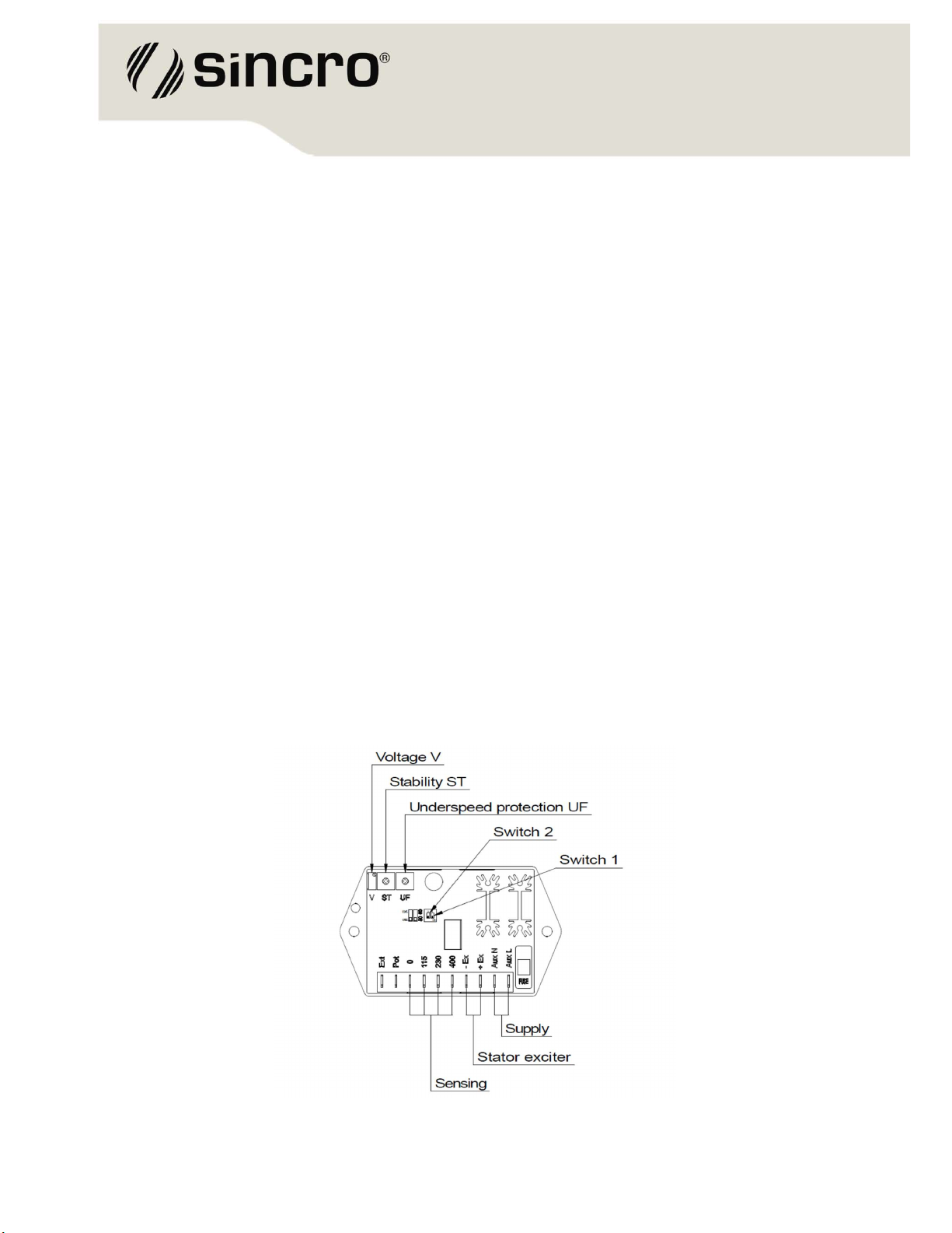
ADJUSTMENTS
Adjusting elements of AVR BL4-U are described as the figure below. AVR BL4-U has two DIP-
Switches: Switch 1 to set the frequency, Switch 2 for remote voltage regulation.
FREQUENCY SELECTION
The frequency selection is done using Switch 1. Set this switch to “ON” for 50 Hz, to “OFF” for 60
Hz.
VOLTAGE ADJUSTMENT
The alternator output voltage is set at the factory, but it can be altered by adjustment of the V
potentiometer on the AVR BL4-U board, or by the external hand potentiometer. Set Switch 2 to “Std”
for the working without external hand potentiometer, set switch 2 to “Ext” for the working with
external hand potentiometer. In this case the external hand potentiometer (5 kohm/3W) has to be
fitted at the terminals Ext and Pot.
STABILITY ADJUSTMENT
The AVR BL4-U includes stability or damping circuit to provide good steady state and transient
performance of the alternator.
The correct setting can be found by running the alternator at no load and slowly turning the stability
ST anti-clockwise until the alternator voltage starts to become unstable.
The optimum or critically damped position is slightly clockwise from this point (i.e. where the
machine volts are stable but close to the unstable region).
Elements for adjustment on AVR BL4-U

5 SINCRO® is a brand of Soga Energy Team ITALY | sogaenergyteam.com | info.sincr[email protected]
UNDER FREQUENCY KNEE ADJUSTMENT
AVR BL4-U incorporates an underspeed protection circuit (UF) which gives a volts/Hz characteristic
when the alternator speed falls below a presettable threshold known as the "knee" point.
The UF knee adjustment is preset at factory at the 47Hz on a 50Hz system or 57Hz on a 60Hz
system. Selection of 50 / 60Hz can be made using the Switch 1.
Figure 3, shows the curves for voltage variation as a function of frequency variation.
For nominal frequency operation, UF is disabled. When rotation decreases (e.g. when shutting
down), excitation decreases, reducing the output voltage of the alternator.
The pre-set "knee" point can be altered, by UF trimpot, according to the needs of each application.
Under frequency “knee”: a) 50 Hz system, b) 60 Hz system
PROTECTION FUSE
The fuse is used to limit the input supply current in order to protect the alternator field.
AVR BL4-U regulator possesses a rectifier that controls the field voltage of the alternator.
For the maximum field voltage, the supplied current at input Aux N is half of the field current, and
the maximum current of the fuse should be a little more than half of the current supplied by the
regulator. The fuse must be: Fast action, 5x20 mm, 3,15A/250V.
TRIMPOTS
Trim pot functions
V = Voltage adjustments;
ST = Stability adjustments;
UF = UF “knee” adjustments.
Trim pot adjustments
V = Turning clockwise, increases voltage;
ST = Turning clockwise, speeds up response;
UF = Turning clockwise, increases the UF protection limit.

6 SINCRO® is a brand of Soga Energy Team ITALY | sogaenergyteam.com | info.sincr[email protected]
INSTALLATION
CONNECTION DIAGRAMS
The figures below show the connection for a alternator with a nominal line voltage of 1Ph 230 Vac
or 3Ph 400Vac. The sensing will be accomplished using the line voltage at input contacts named
400, 230, 115 and 0.
AVR BL4-U Connection diagrams: a) 1Ph - sensing 230V, b) 3Ph - sensing 400 V
CONNECTION TERMINALS
Sensing voltage
400, 0 = 400 Vac
230, 0 = 230 Vac
115, 0 = 115 Vac
Supply voltage
Aux L, AuxN
Alternator field
+Ex, -Ex
External adjustment potentiometer
Ext, Pot

7 SINCRO® is a brand of Soga Energy Team ITALY | sogaenergyteam.com | info.sincr[email protected]
CONNECTION DIAGRAMS WITHOUT AUXILIARY WINDING
The figure below shows the connection for an alternator without the auxiliary winding.
The nominal line voltage are 400Vac. The sensing will be accomplished using the line voltage at
input contacts named 400, and 0.
The power supply is 230V. For the machine 3Ph 400V connect the line U and the neutral N to the
terminals AuxL and AuxN.
AVR BL4-U Connection diagrams without auxiliary winding : a) 3Ph - sensing 400 V
8 SINCRO® is a brand of Soga Energy Team ITALY | sogaenergyteam.com | info.sincr[email protected]
STARTING UP
If a replacement AVR has been fitted, or the re-setting of the voltage adjustment is required, please
proceed as follows:
1. Connect the wires coming from the alternator according to the description in the CONNECTION
DIAGRAMS and the type of alternator to be used.
2. Before running alternator, turn the volts trimpot “V” fully anti-clockwise.
3. Turn remote volts potentiometer (if fitted) to midway position.
4. Turn stability trimpot “ST” to midway position.
5. Connect a suitable voltmeter (0-300V ac) across line to neutral of the alternator.
6. Start alternator set, and run on no load at nominal frequency e.g. 50-53Hz or 60-63Hz.
7. Carefully turn volts trimpot “V” (or external pot, if fitted) clockwise until rated voltage is reached.
8. If instability is present at rated voltage, refer to stability adjustment, and then re-adjust voltage if
necessary.
TURNING OFF
With the U/F protection properly configured, turning off the alternator is done by turning off the
primary mover.
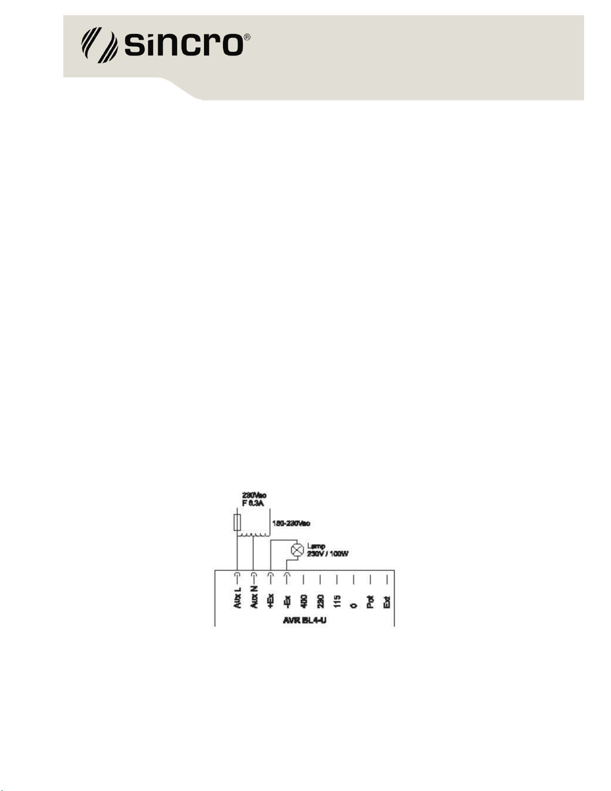
TESTING WITHOUT ALTERNATOR
The figure below shows the connection diagram for AVR testing without alternator, where the
equipment can be verified for proper operation. Changing input voltage in the range 150 -230V ac
the lamp will light. The voltage of the lamp should be the same as the voltage applied on input.
Testing AVR BL4-U without a alternator

9 SINCRO® is a brand of Soga Energy Team ITALY | sogaenergyteam.com | info.sincr[email protected]
MAINTENANCE AND TROUBLE-SHOOTING
PREVENTIVE MAINTENANCE
Periodical inspections of the equipment are required to ensure they are clean, dust and moisture
free. It is essential that all terminals and connections are kept free from corrosion.
TROUBLE-SHOOTING
Trouble Possible
causes
Corrective
actions
Alternator field voltage
does not build up on start-
up.
-
Residual voltage excessively low;
-
Terminals +Ex and - Ex are
inverted.
-
Use external battery (12Vdc) to
force excitation;
-
Invert +Ex and – Ex.
Generated voltage
oscillates at no load.
-
Stability response incorrectly
adjusted
-
Alternator excitation voltage
excessively low
- Unstable engine speed
-
Adjust trim pot ST;
-
Check the frequency/engine
speed
Voltage surges.
-
Lack of sensing;
-
Faulty electronic circuit;
-
Sensing voltage incompatible with
regulator.
-
Check if alternator phases are
present in the sensing circuit;
-
If the regulator is
encapsulated, replace it;
-
Use a compatible sensing
voltage.
Generated voltage decreases
when load is applied, and it
doesn’t return.
-
Speed drop of the prime
mover.
-
U/F protection engaged.
-
Correct speed regulation;
-
Adjust U/F limiter by rotating
trimpot UF clockwise (CW).
During turn-off procedure the
regulator fuse blows.
- U/F protection adjusted for a very
low (or zero) frequency.
- Adjust U/F to a value close to the
operating frequency of the alternator.
Voltage too low
-
Speed too low
-
Field windings short-circuited
-
Main field winding short-
circuited
-
Rotating diodes burnt out
- Increase the drive speed
Voltage too high
-
Adjustment ineffective
-
Faulty AVR
-
Adjust the AVR voltage
-
Change the AVR

10 SINCRO® is a brand of Soga Energy Team ITALY | sogaenergyteam.com | info.sincro@sogaenergyteam.com
SPECIFICATIONS
Characteristics Range
Nominal field current
Nominal current with forced ventilation
Peak current (max. 1min)
External voltage control Through 5K/3W potentiometer
Power Supply Range 170 to 250Vca (±15% of nominal voltage).
Nominal Supply power 230Vac
Maximum field voltage
Operation Frequency 50 or 60Hz.
Underfrequency protection (UF) Adjustable via trimpot.
Voltage drop for frequency variation
Voltage variation in operation (DV/°C)
Voltage adjustment Adjustable via trimpot
External voltage adjustment range ± 15% of VSen.
Temperature of operation. -40° to + 60ºC
EMI Suppression EMI filter
Approximate weight

11 SINCRO® is a brand of Soga Energy Team ITALY | sogaenergyteam.com | inf[email protected]
DIMENSIONS

12 SINCRO® is a brand of Soga Energy Team ITALY | sogaenergyteam.com | info.sincro@sogaenergyteam.com
Other manuals for BL4-U
1
Table of contents
Other Sincro Controllers manuals


Popular Controllers manuals by other brands

KEBCO
KEBCO COMBIVERT F5 Servo installation manual

Magicfx
Magicfx FX-Comm4der User and installation manual

NovaStar
NovaStar LVP6082 user manual

New lift
New lift FST-2XT MRL Installation & commissioning

Tracer
Tracer Profiler T229-2 Operation and maintenance manual

LogiCO2
LogiCO2 Grow CO2 Enrichment Controller user manual

digitalview
digitalview DD-1920-HDBT instructions

Tolomatic
Tolomatic ServoWeld CSW Installation operation & maintenance

superbrightleds
superbrightleds EZD-1C5 user manual

Digistar
Digistar EZ2400 Operator's manual

Aqua Medic
Aqua Medic Qube control Operation manual

Oriental motor
Oriental motor AR Series operating manual


