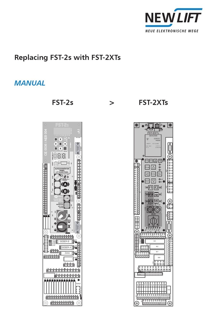
New lift FST-2XT MRL Guide

Controller
INSTALLATION & COMMISSIONING
X.
+
J2
J120
J110
J90
J131
J133
J135
J136
X2
X3
X1
X4
X5
X6
X14 X15
X12
X11
X43
X9
X30
X20 X21
X16
X13
X32
X17
K0 K1 K2 K3 K4 K5 K6 K7 K8 K9 K10 K11 K12 K13
K23
K22
K21
K20
230 V AC
24 V DC
24 V DC
24 V DC
24 V DC
24 V DC
24 V DC
24 V DC
24 V DC
24 V DC
24 V DC
24 V DC
24 V DC
24 V DC
X18 X19
JS
X41
J1
X42
X40
CAN
SKZU
SPB
SPA
TKA
TKB
TKC
NH
FKNH
01 14:03:02
>A< '''@'''
GESCHLOSSEN
FST
STATUS
ERROR
USB-Host
USB-Slave
Drive
Enter
Shift
Select
Func
SAFETYCCTCLOSED
>AX<>BX< '''@'''
00 13:06:56

B Installation & Commissioning FST-2XT
Manufacturer NEW LIFT Steuerungsbau GmbH
Lochhamer Schlag 8
82166 Graefelfing
Phone +49 89 – 898 66 – 0
Fax +49 89 – 898 66 – 300
Mail [email protected]
www.newlift.de
Service line Phone +49 89 – 898 66 – 110
E-mail [email protected]
Date of issue 05.09.2012
Author KH / TB
Release Jan. 2012 / SWB
Hardware version 3.1
Software version FST V2.000-026
Doc. No. mia_fst2XT_2015-05_en
Copyright © NEW LIFT Steuerungsbau GmbH, 2012.
This manual is protected by copyright. All rights, including those of copying, of
reproduction, of translation and of modification, in whole or in part, are reserved by
the publisher.
No part of this description may be reproduced in any form or copied with an
electronic replication system without written permission.
Although great care has been taken in the production of texts and figures, we
cannot be held legally liable for possible mistakes and their consequences.

Installation & Commissioning FST-2XT I
Contents
1 About this manual 1
1.1 General 1
1.2 Signs and symbols used 1
1.3 Further information 2
1.4 How to contact us 2
2 General safety regulations 3
2.1 Qualifications of the installing engineer 3
2.2 Residual dangers 3
2.3 Safety regulations 4
3 FST controller user interface 6
3.1 Keypad functions 6
3.1.1 When switching on 6
3.1.2 Main screen 7
3.1.3 Main menu and test menu 7
3.1.4 Error list 8
3.1.5 Information page 8
3.1.6 Frequency inverter with DCP interface 8
3.2 TFT-Display and messages 8
3.2.1 Main screen 8
3.2.2 Line A – Safety circuit messages 9
3.2.3 Line B – State messages 9
3.2.4 Line C – Status messages 11
3.2.5 Line C - Diagnostic messages 12
3.2.6 Line D - Drive mode messages 12
3.3 Information texts 12
3.3.1 Information page 14
3.4 LEDs 15
4 Installation work 16
4.1 Installation procedure 16
4.2 Delivery contents 17
4.3 Control cabinet 17
4.4 Travelling cable 20
4.5 car components 21
4.5.1 Car top box 21
4.5.2 FPM-1 22
4.5.3 FPM-2 22
4.6 Switching on the controller 23
4.6.1 FST 23
4.6.2 Checking the safety circuit 23
4.6.3 Switching on installation mode 23
4.6.4 car components 24
4.7 Installation drive 24
4.7.1 Installing the positioning system 24

II Installation & Commissioning FST-2XT
4.7.2 Installing magnet switch console and magnets 25
4.7.3 Connecting the LON bus 27
5 Determination of the shaft positioning system 29
5.1 Absolute positioning 29
5.2 Incremental positioning 30
6 Commissioning the FST 31
6.1 Commissioning procedure 31
6.2 Commissioning absolute positioning 32
6.2.1 Setting the type of shaft positioning system 32
6.2.2 Checking the direction of rotation of the encoder 32
6.2.3 Checking / setting the resolution of the encoder 32
6.2.4 Setting bottom floor to 0 34
6.3 Commissioning incremental positioning 35
6.3.1 Setting the type of shaft positioning system 35
6.3.2 Checking the direction of rotation of the encoder 35
6.3.3 Checking / setting the resolution of the encoder 35
6.3.4 Configuring the incremental encoder 37
6.3.5 Setting bottom floor to 0 37
6.3.6 Carrying out learn drive 38
6.4 Carrying out calibration drive 39
6.4.1 Checking positioning accuracy 40
6.5 Levelling adjustment 40
6.5.1 Levelling adjustments on the FST controller 41
6.5.2 Levelling adjustment via HHT handheld terminal 41
6.5.3 Level adjustment via FPM-1 or FPM-2 42
6.6 Commissioning the safety circuit bypass control 42
6.6.1 Operating principle of the safety circuit bypass control 43
6.6.2 Checking the safety circuit bypass control 43
6.6.3 Optimising re-levelling 44
6.6.4 Readjustment 44
6.7 Setting control options 44
6.7.1 Password 44
6.7.2 Crawl drive 45
6.7.3 Door times 45
6.7.4 Test triggering of the monitoring function according to EN 81 46
6.7.5 LON module configuration 48
6.7.6 CMM activation 52
6.7.7 Emergency call filter 52
6.7.8 Creating & loading a backup 52
7 Pin assignment components 53
7.1 FST-2XT 53
7.1.1 FST Jumpers 53
7.1.2 FST Terminal strips and sockets 54
7.2 FSM-2 59
7.2.1 FSM-2 Jumpers 59
7.2.2 FSM-2 Terminal strips and sockets 60
7.3 FPM-1 64

Installation & Commissioning FST-2XT III
7.3.1 FPM-1 Jumpers 64
7.3.2 FSM-1 Terminal strips and sockets 65
7.4 FPM-2 66
7.4.1 FPM-2 Jumpers 67
7.4.2 FSM-2 terminal strips and sockets 67
7.5 EAZ-256/40 and EAZ-256/64 69
7.5.1 EAZ-256/40 and EAZ-256/64 Jumpers 69
7.5.2 EAZ-256/40 and EAZ-256/64 terminal strip 70
7.6 ADM-S and ADM-D 70
7.7 ADM-3 71
7.9 ADM-XF and ADM-XK 72
7.9.1 ADM-XF and ADM-XK Jumpers 72
7.9.2 ADM-XF and ADM-XK Terminal strips sockets 73
8 Commissioning the FST GROUP 74
8.1 General 74
8.2 LEDs FST GROUP 74
8.3 Commissioning steps 75
8.3.1 Switching on the GST controller board 75
8.3.2 Checking basic settings on the GST-XT controller 76
8.3.3 Checking basic settings in FST controllers 76
8.3.4 Establishing bus connections 78
8.3.5 Check the status of the systems 78
8.3.6 Initialising GST-XT controller 78
8.3.7 Testing group function 79
9 Guide 80
9.1 General 80
9.2 The Display 80
9.3 The buttons 81
9.4 The Functions 81
10 Error list 82
10.1 Error messages 82
10.2 Event messages 88
11 Notes 90

IV Installation & Commissioning FST-2XT

About this manual
General
Installation & Commissioning FST-2XT 1
1 About this manual
Read these instructions carefully before installing and commissioning the FST-2XT controller. In addition, chap-
ter „2 General safety regulations“ must be observed. Operation of the FST-2XT controller is briey explained in
chapter „3 FST controller user interface“.
1.1 General
This manual will help you during installation and commissioning of the FST-2XT controller and its components.
The installation and commissioning manual contains important information for safe and proper installation and
commissioning of the FST-2XT controller.
Following these instructions will help to:
› prevent danger,
› avoid repair costs and downtime,
› increase the reliability and lifespan of the FST-2XT controller and of the lift system.
Local, national and on-site regulations regarding health and safety and protection of the environment must be
taken into account in addition to this installation and commissioning manual.
This manual only describes the assemblies of the lift system delivered by NEW LIFT. For information about
components of the lift system that were not manufactured and supplied by NEW LIFT, please refer to the res-
pective user information supplied by the manufacturer or supplier.
Hint:
The dimension and mounting holes and the pins assignmets for the cable conntections have not changed with
respect to the FST-2. The FST-2XT is therefore fully compatible with th FST-2. The FST-2 can be replaced with
a FST-2XT in all circumstances. The FST-2XT has improvments made to the connectivity and user interfaces.
1.2 Signs and symbols used
The following signs and symbols are used for operational instructions:
Symbols
Delivery condition
Settings that are supplied as standard are marked with an asterisk .
System stop
Marks settings requiring a system stop in case a change becomes necessary. The FST-2XT controller displays
the text Liftmustbestoppedtochangethevalue.OK? If you wish to change the value, conrm
with YES, if you do not wish to change the value or wish to change it later, then conrm with NO.
○ Re-start
Marks settings that only become active after a re-start of the FST-2XT or of the components.
► Activity symbol:
Activities described after this symbol must be carried out in the given order.
+ Key combination:
Press the linked keys simultaneously.
Abbreviation used for detailed terminal information
P: power
I: input
O: outpur
L: low active
H: high active
Safety-relevant information
This symbol is located in front of safety-relevant information.
Information notice
This symbol is located in front of relevant information.

About this manual
Further information
2 Installation & Commissioning FST-2XT
1.3 Further information
The following documents, among others, are available for the FST controller and its components:
› FST controller description
› FST manual
› FST short instructions
› FST GROUP manual
› ADM manual
› EAZ-256 manual
› EAZ-LCD and EAZ-VFD manual
› EAZ-TFT manual
› LCS manual
› SAM manual
› Fire recall manual
These and other up to date manuals can be found in the download area of our website unter Service
http://www.newlift.de/service/download
1.4 How to contact us
If, after referring to this manual, you still require assistance, our service line is there for you:
Phone +49 89 – 898 66 – 110
Mon. - Thurs.: 08:00 a.m. – 12:00 p.m. and 1:00 p.m. – 5:00 p.m.
Fr: 08:00 a.m. – 12:00 p.m. and 12:30 – 3:00 p.m.

General safety regulations
Qualifications of the installing engineer
Installation & Commissioning FST-2XT 3
2 General safety regulations
All important safety regulations are summarised in this chapter. These safety instructions must always be adhe-
red to during all work on the installation.
All persons performing installation and commissioning work on the FST-2XT controller must read this chapter
and follow its regulations.
Laws, regulations, guidelines and standards that apply in the country of operation must be followed in addition
to the safety regulations mentioned in this manual.
2.1 Qualifications of the installing engineer
The installing engineer must:
› be over 18 years of age (exception: apprentices who are over 16 years of age and are permanently supervised
by an engineer qualied for training apprentices).
› have rst aid training,
› have theoretical and practical knowledge of regulations and measures for the prevention of re and explosions
in his work area,
› be able to identify, avoid and rectify all dangers that might occur during his work in the shaft and in the operating
rooms,
› be able to identify and rectify all irregularities and faults that might occur during installation and operation of a lift
system,
› have theoretical and practical knowledge of operating principles and requirements of electric controls and drive
systems.
All installation and commissioning work on electric and electronic components of the FST controller must be
performed by or supervised by a qualied electrician.
A qualied electrician has appropriate training and knowledge of regulations that allow him to judge the quality
of the work performed and identify possible dangers (BGV A3).
2.2 Residual dangers
Danger for persons
The following shall always apply during all work on the installation:
Danger to life! Do not touch live parts while working on electrical equipment.
› Before starting work, make sure the system is off circuit.
› Only carry out any installation work on electrical components when these are switched off and in an unpowered
state.
› Only use insulated tools when working on electrical system components.
Risk of injury when lifting or moving the control cabinet if it falls down or tips over.
› Only transport and lift the control cabinet with suitable equipment (lift truck, hoisting gear etc.).
› All workers must be trained in using these aids and must observe all applicable special regulations to avoid
accidents.
Falling parts or parts protruding into the shaft. Risk of serious injury or death.
› Block the shaft access points.
› Before beginning installation work, remove all foreign parts and assembly aids that are not required from the
shaft.
Electrical hazard, leaking gas or water due to pierced supply lines. Risk of serious injury or death.
› Make sure no supply lines are in the installation location before starting any installation work.

General safety regulations
Safety regulations
4 Installation & Commissioning FST-2XT
Danger of falling! Installing engineers and unauthorised persons can fall down the shaft. Risk of serious injury or
death.
› Block the shaft access points.
› Use suitable protection (e.g. safety harnesses, scaffoldings) when working on or in the shaft.
Danger of crushing due to intentional or accidental car movement. Risk of serious injury or death.
› Block the shaft access points.
› Before starting any work, make sure that there are no persons in the shaft or in the vicinity of moving parts of
the drive.
› Prevent unauthorised operation of the controller.
Risk of material damage
The following shall always apply during all work on the installation:
Electrostatic charging
› Keep the electronic assembly in its original packaging until installation.
› Before opening the original packaging, a static discharge must be performed. To do this, touch a grounded
piece of metal.
› During work on electronic assemblies, periodically perform this discharge procedure.
Electronic assemblies are destroyed by defective, interchanged or incorrectly mounted connectors, short-circui-
ting or excess voltage.
› Check plugs for mechanical damage.
› Never change pre-assembled connectors or cables.
› Only connect loose or torn off wires according to circuit diagram details if this is possible on site (suitable mate-
rial and tools must be available).
› Pay attention to coding pins and latch lugs.
2.3 Safety regulations
General
› The instructions of the lift manufacturer and the instructions in this manual must be followed during installation
and commissioning of the lift system.
› The shaft must be secured against unauthorised trespassing during installation and commissioning.
› Assemblies, devices and cables must be installed and fastened securely and permanently.
› Loads must be moved with suitable aids (lift trucks, hoisting gear etc.).
› Sharp and pointed tools or other potentially dangerous objects may only be carried along in clothing if suitable
protective measures have been taken to rule out any danger.
› Alcohol and drugs must not be consumed before and during installation and commissioning.
Documentation
› A copy of the installation and commissioning manual must be available to the installing engineer at the time of
installing and commissioning the FST-2XT controller and its components.
› A copy of the installation and commissioning manual and the wiring diagrams must be kept in the control cabi-
net at all times after installation.
› The wiring diagrams supplied with the FST-2XT controller are binding. Changes must only be made after con-
sulting NEW LIFT and must be documented in writing on the system.
› The factory test logs of the FST-2XT controller remain with NEW LIFT.
Electricity
› Regulations for installing and operating electrical equipment (VDE 0100) and regulations of local utilities must
be followed.
› The specied distances between different electrical assemblies must be controlled and maintained.
› All installation work must be carried out with the system shut down and off circuit.
› All cables and wires must be installed with sufcient strain relief.
› The neutral and ground wires must be routed separately.
› The control cabinet must be supplied with a clockwise rotary eld.

General safety regulations
Safety regulations
Installation & Commissioning FST-2XT 5
Working in the shaft
› Any work in the shaft requires perfect and permanent communication between the supervisor on the FST-2XT
controller in the motor room and the workers in the shaft.
› Components in the shaft must be arranged or secured in such a way that persons accessing the shaft for ins-
pection, maintenance or repair purposes are not in danger.
› The maximum load of the lift system must not be exceeded.
› The specied overruns of the emergency end switches in relation to the speed must be observed.
› The emergency installations must not be activated during normal operation.
› All emergency installations and braking systems must be checked for troublefree operation and all shaft entran-
ces closed off before beginning work.
› Installation and operation are prohibited if other persons could be in danger.
› Workers must be secured against falling.
› In case of any work interruptions, the car must be moved to the lowest stop position, the controller switched off
and the power supply (e.g. UPS) permanently disconnected.
Personal safety equipment of the installing engineer
› Eye protection
› Safety boots
› Protective helmet
› Safety harness
› Clothing suitable to the ambient conditions of the installation location
› Jewellery, watches and similar items may not be worn; a hair net must be used if applicable.
Handling electronic assemblies
› Leave electronic assemblies in their original packaging until installation.
› Touch a grounded piece of metal prior to opening the original packaging to prevent damage from static charges.
› All bus inputs and outputs not in use must be equipped with a terminal resistor (terminator). Exception: FSM-2
X23 and FST X2 are only for use with the HHT hand-held terminal and must not be equipped with a terminator.
Waste disposal
› All packaging material must be disposed of in an environmentally acceptable manner; paper, plastic, metal,
electronic assemblies etc. must be recycled.

FST-2XT controller user interface
Keypad functions
6 Installation & Commissioning FST-2XT
3 FST-2XT controller user interface
The user interface of the FST-2XT controller is located on the FST-2XT main circuit board in the control cabinet
of the lift system. The FST-2XT user interface consists of front panel, LC-Display, keypad and LEDs.
SKZU
SPB
SPA
TKA
TKB
TKC
NH
FKNH
01 14:03:02
>A< '''@'''
GESCHLOSSEN
FST
STATUS
ERROR
USB-Host
USB-Slave
Drive
Enter
Shift
Select
Func
Fig. 3.1: FST controller user interface
3.1 Keypad functions
The FST-2XT controller is operated using seven keys, which are located below the display. These keys are
refered in this manuel as for Drive, for Enter and is for Shift.
The four blue buttons on the right side of the front panel are described in more details at chapter 9.
3.1.1 When switching on
SAFETYCCTCLOSED
>AX<>BX< '''@'''
00 13:06:56
Pressing and holding the key during the switch-on sequence of the FST-2XT starts
emergency operation. In emergency operation, no drives are possible. Emergency operation
is required if the FST-2XT cannot be switched on in normal mode due to a malfunction. The
complete FST-2XT menu and the PC-Card functions are active in emergency operation!
SAFETYCCTCLOSED
>AX<>BX< '''@'''
00 13:06:56

FST-2XT controller user interface
Keypad functions
Installation & Commissioning FST-2XT 7
3.1.2 Main screen
SAFETYCCTCLOSED
<A> '''@'''
00 13:06:56
Set car call to top oor
Set car call to bottom oor
Switch landing control on and off (switch function)
Open test menu
Open main menu
Activate emergency mode: press before switching on and keep pressed until the FST has
fully run up (see FST manual)
+Set car call to next oor up
+Set car call to next oor down
+Scroll through the right status messages in line C
+Scroll through the left status messages in line C
+Display information page
++Switch diagnostic message in line C on or off
+++Perform controller RESET
Switch to converter menu (DCP)
3.1.3 Main menu and test menu
MAINMENU
Drive
Config
>Positioning
Move cursor up
Move cursor down
Exit submenu
Change menu level
Select submenu / menu item
ClockSetting
13:45:01
Increase value
Decrease value

FST-2XT controller user interface
TFT-Display and messages
8 Installation & Commissioning FST-2XT
Move cursor left
Move cursor right
Conrm setting
3.1.4 Error list
ERROR[00037/00040]
28.0910:18:26 [012]
Doorclosefailure
FLOOR:03V00R01I00
Switch to 2nd to 8th information byte in line D
Switch to initial display in line D
+To previous error message
+To next error message
3.1.5 Information page
-FSTInformation-
HWVer.: 12-16
SWVER:: V 1.100-0026
18/05/1999
Scroll one line up
Scroll one line down
Back to main screen
3.1.6 Frequency inverter with DCP interface
Frequency inverters with DCP interface can be operated and congured from the FST-2XT menu
(FST X11 connected). The display of the frequency inverter is simulated on the FST-2XT display by
pressing the -key once. The FST-2XT keys then perform the function of the frequency inverter
keys. The FST-2XT display is restored by pressing the -key again.
3.2 TFT-Display and messages
The TFT-Display is divided into two sections, the upper portion consists of four lines (A, B, C and D) with 20
columns each. After switching on and during normal operation, the FST-2XT controller displays the main screen.
The lower portion of the display is described in Chapter 9.
3.2.1 Main screen
SAFETYCCTCLOSED
>AX< '''@'''
00 13:06:56

FST-2XT controller user interface
TFT-Display and messages
Installation & Commissioning FST-2XT 9
A Maximum active state of the safety circuit
B Active state or error
C Status of the lift system / diagnostic message
D Data for current drive mode
Line C has a special status. In normal mode (after switching on), it displays status messages (see „3.2.4 Line
C – Status messages“). By switching with key combination ++, it displays diagnostic messages (see
„3.2.5 Line C - Diagnostic messages“).
See also „3.1 Keypad functions“.
3.2.2 Line A – Safety circuit messages
Display Description
SAFETYCCTCLOSED The safety circuit is completely closed (FST X14.1, FST X14.2).
SFTY-CLOSEDMISSING The input "Safety circuit closed" has no power. Possible causes:
› Terminal FST X14.1 has no power (normally bridged with X14.2)
› Relay K14 (230V) on the FST is faulty
DOORLOCK-AOPEN The shaft door contact of door side A is interrupted (FST X14.2, X14.3) .
DOORLOCK-BOPEN The shaft door contact of door side B is interrupted (FST X14.3, X14.4) .
DOORAOPEN The car door contact of side A is interrupted (FST X14.4, X14. 5).
DOORBOPEN The car door contact of side B is interrupted (FST X14.5, X14. 6).
DOORCOPEN The car door contact of side C is interrupted (FST X14.6, X14. 7).
MANUALDOOROPEN A manual door contact is interrupted (FST X14.6, X14.7).
EMERGENCYSTOP An emergency switch in the shaft is interrupted (terminals FST X14.7, X14.8).
EMERGENCYSTOPCAR An emergency switch on the car is interrupted (FST X32.4).
The messages DOORCOPEN,MANUALDOOROPEN and EMERGENCYENDSWITCH (line B) are triggered by
the same safety circuit input of the FST-2XT (TC input: FST X14. 6) and exclude each other.
3.2.3 Line B – State messages
Display Description
LOW24V! The 24V power supply of the FST-2XT board (FST X1.1, X1.2) is below the
permitted range of 17 V. Check power supply and cables in the supply line.
POST-EMERGENCYSTOP Landing control is blocked by a safety circuit interruption (interruption before
terminal FST X32.4), line A displays EMERGENCYSTOP.
LANDINGCONTROLOFF The landing control has been switched off manually. Possible causes of the
shutdown:
› Key of the FST keypad
› Programmable input of an external RIO module
› Input FST X1.14
› Programmable input on the FST-2XT controller
› Key switch on car panel (FPM-1 X4.37 / FPM-2 X1.13)
› Key switch on landing control panel (ADM input X3.12 / X3.13)
FIREMANMODE A re input is active. Possible causes of re recall:
› Fire input on landing call module (ADM input X3.12 / X3.13)
› Programmable input on the FST controller
› GST Group Controller (see GST manual)
END-SWITCHTEST The manual end-switch test is being executed (see test menu in the FST
manual).
ES-SPEEDMON.TEST The manual test of the deceleration monitoring function at the top and bottom
end oors is running (see test menu in the FST manual).

FST-2XT controller user interface
TFT-Display and messages
10 Installation & Commissioning FST-2XT
Display Description
EVACUATION The controller is in evacuation mode. The reason for the evacuation signal may
be:
› A programmable input on the FST-2XT controller
› A programmable input on the GST Group Controller
› LMS via protocol adapter module
SENDFAX The controller is in fax mode (see Installation & Commissioning – Fax modem).
LIFTOFF The controller has been switched off. Possible causes of switch-off:
› Car lighting failure
› Input "Car Lighting OFF", FST X1.13
› Programmable I/O port of a RIO module (external)
› Programmable I/O port of the FST-2XT controller
› Externally by the GST Group Controller or the LMS Lift Monitoring System
FIREMANSERVICE Fireman service mode has been activated. Possible causes of signal:
› Key switch reman service in car operating panel (FPM-1 X4.4 / FPM-2 X2.13)
› Programmable I/O port of the FST-2XT controller
› The state was saved after a power failure and has been reconstructed. The
Fireman Mode Reset function must be executed to reset this state.
› Key switch on landing control panel (ADM input X3.12 / X3.13)
› GST Group Controller (see GST manual)
FILETRANSFERACTIVE The controller is in data transmission mode to transfer les to a GST Group Cont-
roller or to a PC.
Attendantoperation The attendant controller is active.
INSPECTIONMODE The controller is in inspection mode (input FSM-2 X22.2).
Attention: Line A of the FST-2XT display must show EMERGENCYSTOPCAR!
CALIBRATION-- The calibration drive has been started. A ticker text displays the status.
After completion of a successful calibration drive, the message CALIBRATION
OK!appears. If the drive is interrupted prematurely, CALIBRATIONABORT!
appears. Find the error in the error list and repeat the calibration drive
APRON-EXTENDED! The car apron is open (due to a shaft door interruption). Monitoring is performed
via a programmable input on the FST-2XT controller.
LEARNDRIVEACTIVE The controller performs a learn drive.
LEARNDRIVE-START The controller starts a learn drive.
LEARNDRIVE-OK! The learn drive has been completed successfully.
LEARNDRIVE-ABORT! The learn drive has been aborted due to an error. Find the error in the error list
and repeat the learn drive.
SAFETYCURTAIN The safety curtain replacing the car door has been interrupted. The contact is
in the safety circuit instead of the car door contacts (see System description –
Safety curtain).
DRM... A runtime monitoring error has occurred, the installation is brought to a standstill.
Possible causes are, amongst others:
› Start-up problems
› Runtime monitoring
› Encoder failure
› car communication
› Motor failure
› Forced stop
› Emergency end switch
› Door failure
INSTALLATIONMODE The controller is in installation mode.
EMERGENCYENDSWITCH The top emergency end switch is interrupted (FST X14.6, X14.7)
ORIENTATION Only incremental positioning:
After switching on, the controller performs an orientation drive to an end oor.
The orientation drive can take place automatically or when the rst call is placed.
PARKINGACTIVE The controller sends the car to the programmed parking oor.

FST-2XT controller user interface
TFT-Display and messages
Installation & Commissioning FST-2XT 11
Display Description
LANDINGPRIORITY A priority landing drive has been triggered. Possible causes of signal:
› Key switch on landing control panel (ADM input X3.12 / X3.13)
› Programmable input on the FST-2XT controller
› Programmable input on an external RIO module
CARPRIORITY A priority car drive has been triggered. Possible causes of signal:
› Key switch on car panel (FPM-1 X4.37 / FPM-2 X1.13)
› Automatically after a type Auto 2 priority landing drive
AUXILIARYMODE The controller is in auxiliary mode (input FST X18.2).
Attention: Line A of the FST-2XT display must show EMERGENCYSTOP!
HOMINGACTIVE The hydraulic lift is sent to the lowest landing.
SERVICEMODE The controller is in service mode (see test menu in the FST manual).
SERVICEREQUIRED! One of the service counters has exceeded a set limit.
SYSTEMSTOP The controller has been stopped via the FST-2XT menu.
OVERLOAD The overload input on the FSM or on a programmable input is active.
USERERROR A user error has occurred (you can dene up to three error messages as user
errors). The number of the error is displayed.
V.I.P.MODE The controller is in VIP mode. The source for the VIP mode can be:
› LMS via protocol adapter module
› Programmable input on the FST-2XT controller
› FPM-2 X2.14 in the car operating panel
FULLLOAD The full load input on the FSM is active.
3.2.4 Line C – Status messages
Line C is divided into two parts and displays one of the following status messages in the left part and one in the
right part. This way you can select which two status messages you want shown simultaneously on the display.
Select the status message in the left-hand area with +, in the right-hand area with +.
Status Display Description
Car doors <A> Door A completely open
>A< Door A completely closed
{A} Door A is opening
}A{ Door A is closing
<A*> Photocell or reversing contact door A active
<AX> Door A is locked (test menu)
<AL> Door is in loading mode (loading button has been pressed)
-A- Door A is stopped
?A? State of door A is unknown (check door end switches)
{{}} Door open button active
}}{{ Door close button active
<{}> Door open button permanently pressed
>}{< Door close button permanently pressed
Shaft positioning ZZone message active
FZone message missing
-Car is in levelled position
'''@'' Car position relative to level position (2.5 mm / pixel)
†Bottom correction switch active
°Top correction switch active
Car position P=6200 Current car position in relation to the level position of the bottom
oor in mm.
Levelling Pd=-2 Current position of the car relative to closest level position in
[mm]

FST-2XT controller user interface
Information texts
12 Installation & Commissioning FST-2XT
Status Display Description
Car speed V=1300 Current speed of the car in [mm/s]
Set / actual speed '''''''-- Comparison between set and actual speed of the car. The left
bar is a graphic display of the relation between actual speed and
the set speed on the right. (Only displayed if no level position is
displayed in the other area)
Motor-Hours BS=4351 Operating hours of the drive
Drive counter FZ=123456 Number of completed drives
Load measurement L=100kg Displays the current car load (only in combination with LCS)
Memory occupied Rec:45% Memory occupied on the PC-Card when recording.
The door states marked with A also apply to doors B and C.
3.2.5 Line C - Diagnostic messages
Line C can be switched from status messages to diagnostic messages with key combination ++. You
will nd further information in the FST manual.
3.2.6 Line D - Drive mode messages
Column Display Description
1TAuto test drive active
SNo serial connection to the frequency inverter (FST X11)
sData transmission to the frequency inverter via serial connection is faulty (FST
X11)
2`Direction of travel UP
\Direction of travel DOWN
3-4 10 Current oor for the car
5-8 [13] car call and landing call on target oor
[13 car call to target oor
13] Landing call to target oor
X13 car control blocked
13X Landing control blocked
9 Not assigned
10 GFST-2XT is integrated in a GST Group Controller.
gFST-2XT is integrated in a GST Group Controller but communication with the GST
is faulty
s"Separated" group participants
PDrive temporarily stopped
11 RFlashes while recording data on the PC card
FCard is cleared
BBank controller: user group active
9-11 FTX Data exchange from FST-2XT active (from FST to GST, LMS, etc.)
FRX Data exchange to FST-2XT active (from GST, LMS, etc. to FST)
12 Not assigned
13-20 10:44:12 Current time of the FST-2XT
3.3 Information texts
When triggering actions in the FST-2XT menu, information texts may appear in the display. They contain infor-
mation on the result of the respective action.

FST-2XT controller user interface
Information texts
Installation & Commissioning FST-2XT 13
Display Description
EMERGENCYMODE! The controller is in emergency mode. Drives are not possible. Emer-
gency operation is activated by pressing the key while switching
the system on.
Landingcallbuttonstuck:
03/A
Car-callbuttonstuck:02/B
The landing call from the specied oor and door side is permanently
activated (is stuck). The message is repeated every minute until the
error has been corrected.
ADMunconfigured! A landing call module connected to the shaft bus is not congured.
Inform NEW LIFT service line!
DRIVEINHIBITON! Mutual start-up blocking via the LMS bus is active. Starting will be
delayed until the other networked systems have completed their acce-
leration phases.
PleaseWait! The triggered action has not been completed. Please wait!
REMOVEWRITE-PROTECT The PC-Card is write-protected. Move the door lock on the PC card to
disable the write protect function.
FAX/SMSSENTOK! A status fax was sent successfully via the modem interface.
FAX/SMS->GST! A fax/SMS (text message) is sent to the group controller where it will
be sent via the FAX-modem.
FAX/SMSNOTSENT! Transmission of a status fax via the modem interface was aborted.
Check modem and telephone connection. MAINMENU/Config/
Modem/Fax/LMS
FILENOTFOUND! The inserted USB-Stick or SD-Card does not contain the le(s)
required for the triggered action.
FSTSoftwareUpdate The software of the FST-2XT is updated with the USB-Stick. The
progress in [%] is displayed in line C.
GSTUPDATECOMPLETE! The software update of the GST Group Controller has been completed
successfully.
ZONEISINCORRECT! The zone measured during the learn drive is too long (max - 300mm to
+300mm)
Calibrationabort! The calibration drive was aborted. Check function of connected drive
speeds. Locate reason for drive abort in the error list.
NO<TC>SIGNAL The car is on the top oor and the correction top signal is missing (only
incremental positioning). Check function of TC switch. Check settings
in MAINMENU/Positioning/Increm.Positioning./
TC/BClevel.
NO<BC>SIGNAL! The car is on the bottom oor and the correction bottom signal is
missing (only incremental positioning). Check function of BC switch.
Check settings in MAINMENU/Positioning/Increm.Posi-
tioning./TC/BClevel.
CONFIGTRANSFERERR! An error has occurred during copying of the controller conguration.
CONFIGTRANSFEROK! Controller conguration copied successfully.
CONFIG(D)CORRUPT! A parameter of the drive conguration is not plausible. Change a
parameter in MAINMENU/Drive and undo the change again. The
information text disappears after saving the settings.
CONFIG(S)CORRUPT! A parameter of the system conguration is not plausible. Change a
parameter in MAINMENU/Config and undo the change again. The
information text disappears after saving the settings.
LCS(L1)calibrated! The LCS empty load measurement was performed.
LCS(L2)calibrated! The LCS reference load measurement was performed.
LEARNDRIVEFAILURE! The started learn drive was not successful. Check function of signals
zone B, bottom correction (BC) and top correction (TC). Locate reason
for drive abort in the error list.
LEARNDR.STARTFAILURE! The started learn drive was aborted due to the car not moving even
with pre-selection active.
DRV–TESTSTARTED! A DRV test was triggered.
DRV–TESTFINISHED! The DRV test was not completed successfully.
CARNUISANCEDETECT! The car nuisance protection function has triggered.
See MAINMENU/Config/AntiNuisance.

FST-2XT controller user interface
Information texts
14 Installation & Commissioning FST-2XT
Display Description
NOTINTHEZONE! The started learn drive cannot be performed because the car is not in
the door zone of the bottom oor. Check function of zone B signal and
settings in MAINMENU/Positioning/Increm.Positng./
ZoneB-Level.
NOTINFLOOR-0! The started learn drive cannot be completed because the car is not on
the bottom oor (check bottom correction switch, BC)
NOTFROMTHISFLOOR! The car is at an end oor. The end switch test cannot be started from
this oor.
EMERG.-CALLPRESSED An emergency call button was pressed or is defective (see wiring
diagram).
ONLYFROMENDFLOOR! The triggered DRV test can only be started from an end oor.
CheckingUpdateFile Updating the software. The inserted mass storage is checked for
update les.
RECORDINGRE-START! An already-started recording was restarted.
RECORDINGSTOPPED! Recording was stopped.
RECORDINGNEWSTART! Recording is restarted.
SDcardok This message will ash 5 times shortly when the SD card is inserted.
SDcardremoved This message will ash 5 times shortly when the SD card was
removed.
USBstickok This message will ash 5 times shortly when the USB stick is inserted.
USBstickremoved This message will ash 5 times shortly when the USB stick was
removed.
UPDATEFILEFOUND The le required for the software update was found on the mass
storage. The software is updated.
UPDATECOMPLETE! The software update of the LON modules was completed successfully.
WAITINGTORESET... Automatic Reset after changing a basic parameter (e.g. Drive type).
This may take a few seconds.
EXCESSIVESLIPPAGE!! During the last drive of the learn drive, hysteresis of the connected
magnet switches TC, BC and zone B was detected (only incremental
positioning). This message appears if the result of the measurement is
greater than 10 mm. Hysteresis will then automatically be limited to 10
mm.
DOOR-NUDGING! Nudging (forced closure) of the car door is active. Photocell and rever-
sing contacts are ignored. See MAINMENU/Doors/Doors-
Selective/PhotocellandMAINMENU/Doors/Doors-
Selective/NudgeTime
3.3.1 Information page
The information page contains important information on the individual conguration of your FST controller.
It can be accessed with key combination + and closed with . and serve for navigation
within the information page.
-FSTInformation
HWVer.: FST-2XT
SWVER.: V2.000-0026
09/12/2012
Messages in lines B, C and D
Display Description
HWVER.:FST-2XT Hardware version of the FST-2XT circuit board;
SWVer.:V2.000-0026
:09/12/2012
Software version with release date
BootVer:0104 Software version of the operating system
Other manuals for FST-2XT MRL
3
Table of contents
Other New lift Controllers manuals


