manuals.online logo
Brands
  1. Home
  2. •
  3. Brands
  4. •
  5. superbrightleds
  6. •
  7. Controllers
  8. •
  9. superbrightleds EZD-1C5 User manual

superbrightleds EZD-1C5 User manual

1 - 5-zone LED dimmer remote (battery included)
1 - magnetic remote mount and mounting hardware
EZD-4C8A has four 8 A output channels
EZD-1C8A has one 8 A output channel
Note: Output channels cannot be controlled independently
and will all dim or brighten together—multiple channels are
to accommodate additional electrical load.
Parts Included
Compatible Controllers
Safety and Notes
Specications
Remote Functions
Pairing
Multiple remotes can be paired to a controller, and each remote can be
paired to multiple controllers. If a system with multiple controllers and/or
multiple remotes has components that are not in sync, unpair and re-pair
until all components are synced properly.
Controller and Remote
Begin pairing by pressing the “pairing switch” button on the controller.
Next, press one of the zone on (I) buttons on the remote to assign the
controller to that zone. Lights will blink once to indicate pairing.
Note: To unpair remote(s), press and hold the controller’s “pairing switch”
button until the lights blink twice.
Master/Slave Controller Setting
EZD-4C8A controllers can be set to master or slave by positioning
a jumper as illustrated on the controller. The main controller should
be set as the master, which will emit a synchronization signal to any
associated controllers set to slave.
Note: Master and slave setting will only a󰀨ect controllers paired to the
same zone.
Remote
Controllers
• Product should be installed and serviced in accordance
with applicable national, state, and local building and
electrical codes.
• To reduce the risk of electric shock, ensure that the main
power source and any applicable circuit breakers are
switched o󰀨 before performing any installation or wiring
procedures.
Master On/O󰀨 Buttons
Turn on (I) / o󰀨 (O) all controllers that are paired to the remote.
Zone On/O󰀨/Intensity Buttons
Buttons are labeled 1–5, one for each zone. Pressing a zone on (I) /
o󰀨 (O) button will turn that zone on/o󰀨. When a zone is on, holding the
(I) or (O) buttons to the left or right of the zone number will brighten
or dim that zone.
Note: All lights that are paired to a zone will dim together. Individual
channels on multi-channel remotes have no independent adjustment.
FCC Statement
Set-Up Instructions
Remote
Remove the battery cover, then remove the
plastic isolator around the battery.
Controller
With supply power o󰀨, loosen the labeled
terminal screws and connect strip(s) as you
would during installation. Turn power on to
check proper operation.
EZD-1C5
Battery CR2025
Operating Frequency 868 MHz
FCC ID Number 2AHST-RF283X
This device complies with part 15 of the FCC Rules. Operation
is subject to the following two conditions: (1) This device may
not cause harmful interference, and (2) This device must
accept any interference received, including interference that
may cause undesired operation. Any changes or modications
in construction of this device which are not expressly approved
by the party responsible for compliance could void the user’s
authority to operate the equipment.
Wireless Remote for EZ Dimmer Series Controllers
Important: Read all instructions prior to installation. EZD-1C5
4400 Earth City Expy, St. Louis, MO 63045 866-590-3533 superbrightleds.com
Rev Date: V0.1 03/10/2020
5yr
User Manual
Check product label for specific electrical
specifications related to installation.
Improper installation will void warranty.
Connection Diagram
Example Wiring Diagrams
EZD-4C8A Controller
EZD-1C8A Controller
Common Output (+)
Channel 2 Output (-)
Channel 1 Output (-)
Channel 3 Output (-)
Output (+)
Output (-)
Input (+)
Input (+)
Input (-)
Input (-)
Channel 4 Output (-)
Pairing Switch
Optional Push Switch
Pairing Switch
Jumper
Single Color Application / EZD-1C8A
Single Color Application / EZD-4C8A
Diagrams are for example only. Multiple strips can be connected to a single output circuit as required,
but maximum load of each circuit must be observed. When using remote EZD-1C5, dimming can not
be controlled by individual output channel, so any dimming adjustments will a󰀨ect all connected strips
in a zone (connected to the same controller) simultaneously.
Optional Push Switch
Single Press Turns LEDs on/o󰀨
Hold Press Increases or decreases LED
intensity until you release
Wireless Remote for EZ Dimmer Series Controllers
Important: Read all instructions prior to installation. EZD-1C5
4400 Earth City Expy, St. Louis, MO 63045 866-590-3533 superbrightleds.com
Rev Date: V0.1 03/10/2020
User Manual
DC INPUT
OUTPUT
V+
V-
V +
WW/R -
CH1
CW/G -
CH2
WW/B -
CH3
CW/W -
CH4
12–36VDC
Pairing
Switch
MASTER SLAVE
DC INPUT
OUTPUT
V+
V-
V +
WW/R -
CH1
CW/G -
CH2
WW/B -
CH3
CW/W -
CH4
12–36VDC
Pairing
Switch
MASTER SLAVE
DC INPUT
OUTPUT
V+
V-
V +
WW/R -
CH1
CW/G -
CH2
WW/B -
CH3
CW/W -
CH4
12–36VDC
Pairing
Switch
MASTER SLAVE
DC INPUT
OUTPUT
V+
V-
V +
WW/R -
CH1
CW/G -
CH2
WW/B -
CH3
CW/W -
CH4
12–36VDC
Pairing
Switch
MASTER SLAVE
DC INPUT
OUTPUT
V+
V-
V +
WW/R -
CH1
CW/G -
CH2
WW/B -
CH3
CW/W -
CH4
12–36VDC
Pairing
Switch
MASTER SLAVE
DC INPUT
OUTPUT
V+
V-
V +
WW/R -
CH1
CW/G -
CH2
WW/B -
CH3
CW/W -
CH4
12–36VDC
Pairing
Switch
MASTER SLAVE
DC INPUT
OUTPUT
V+
V-
V +
WW/R -
CH1
CW/G -
CH2
WW/B -
CH3
CW/W -
CH4
12–36VDC
Pairing
Switch
MASTER SLAVE
CH1
INPUT
Pairing Switch
GND
Push
Switch
CH1
INPUT
Pairing Switch
GND
Push
Switch
DC INPUT
OUTPUT
V+
V-
V +
WW/R -
CH1
CW/G -
CH2
WW/B -
CH3
CW/W -
CH4
12–36VDC
Pairing
Switch
MASTER SLAVE
DC INPUT
OUTPUT
V+
V-
V +
WW/R -
CH1
CW/G -
CH2
WW/B -
CH3
CW/W -
CH4
12–36VDC
Pairing
Switch
MASTER SLAVE
DC INPUT
OUTPUT
V+
V-
V +
WW/R -
CH1
CW/G -
CH2
WW/B -
CH3
CW/W -
CH4
12–36VDC
Pairing
Switch
MASTER SLAVE
DC INPUT
OUTPUT
V+
V-
V +
WW/R -
CH1
CW/G -
CH2
WW/B -
CH3
CW/W -
CH4
12–36VDC
Pairing
Switch
MASTER SLAVE
DC INPUT
OUTPUT
V+
V-
V +
WW/R -
CH1
CW/G -
CH2
WW/B -
CH3
CW/W -
CH4
12–36VDC
Pairing
Switch
MASTER SLAVE
DC INPUT
OUTPUT
V+
V-
V +
WW/R -
CH1
CW/G -
CH2
WW/B -
CH3
CW/W -
CH4
12–36VDC
Pairing
Switch
MASTER SLAVE
DC INPUT
OUTPUT
V+
V-
V +
WW/R -
CH1
CW/G -
CH2
WW/B -
CH3
CW/W -
CH4
12–36VDC
Pairing
Switch
MASTER SLAVE
DC INPUT
OUTPUT
V+
V-
V +
WW/R -
CH1
CW/G -
CH2
WW/B -
CH3
CW/W -
CH4
12–36VDC
Pairing
Switch
MASTER SLAVE
CH1
INPUT
Pairing Switch
GND
Push
Switch
CH1
INPUT
Pairing Switch
GND
Push
Switch
DC INPUT
OUTPUT
V+
V-
V +
WW/R -
CH1
CW/G -
CH2
WW/B -
CH3
CW/W -
CH4
12–36VDC
Pairing
Switch
MASTER SLAVE
DC INPUT
OUTPUT
V+
V-
V +
WW/R -
CH1
CW/G -
CH2
WW/B -
CH3
CW/W -
CH4
12–36VDC
Pairing
Switch
MASTER SLAVE
DC INPUT
OUTPUT
V+
V-
V +
WW/R -
CH1
CW/G -
CH2
WW/B -
CH3
CW/W -
CH4
12–36VDC
Pairing
Switch
MASTER SLAVE
DC INPUT
OUTPUT
V+
V-
V +
WW/R -
CH1
CW/G -
CH2
WW/B -
CH3
CW/W -
CH4
12–36VDC
Pairing
Switch
MASTER SLAVE
DC INPUT
OUTPUT
V+
V-
V +
WW/R -
CH1
CW/G -
CH2
WW/B -
CH3
CW/W -
CH4
12–36VDC
Pairing
Switch
MASTER SLAVE
DC INPUT
OUTPUT
V+
V-
V +
WW/R -
CH1
CW/G -
CH2
WW/B -
CH3
CW/W -
CH4
12–36VDC
Pairing
Switch
MASTER SLAVE
DC INPUT
OUTPUT
V+
V-
V +
WW/R -
CH1
CW/G -
CH2
WW/B -
CH3
CW/W -
CH4
12–36VDC
Pairing
Switch
MASTER SLAVE
DC INPUT
OUTPUT
V+
V-
V +
WW/R -
CH1
CW/G -
CH2
WW/B -
CH3
CW/W -
CH4
12–36VDC
Pairing
Switch
MASTER SLAVE
CH1
INPUT
Pairing Switch
GND
Push
Switch
CH1
INPUT
Pairing Switch
GND
Push
Switch
DC INPUT
OUTPUT
V+
V-
V +
WW/R -
CH1
CW/G -
CH2
WW/B -
CH3
CW/W -
CH4
12–36VDC
Pairing
Switch
MASTER SLAVE
DC INPUT
OUTPUT
V+
V-
V +
WW/R -
CH1
CW/G -
CH2
WW/B -
CH3
CW/W -
CH4
12–36VDC
Pairing
Switch
MASTER SLAVE
DC INPUT
OUTPUT
V+
V-
V +
WW/R -
CH1
CW/G -
CH2
WW/B -
CH3
CW/W -
CH4
12–36VDC
Pairing
Switch
MASTER SLAVE
DC INPUT
OUTPUT
V+
V-
V +
WW/R -
CH1
CW/G -
CH2
WW/B -
CH3
CW/W -
CH4
12–36VDC
Pairing
Switch
MASTER SLAVE
DC INPUT
OUTPUT
V+
V-
V +
WW/R -
CH1
CW/G -
CH2
WW/B -
CH3
CW/W -
CH4
12–36VDC
Pairing
Switch
MASTER SLAVE
DC INPUT
OUTPUT
V+
V-
V +
WW/R -
CH1
CW/G -
CH2
WW/B -
CH3
CW/W -
CH4
12–36VDC
Pairing
Switch
MASTER SLAVE
DC INPUT
OUTPUT
V+
V-
V +
WW/R -
CH1
CW/G -
CH2
WW/B -
CH3
CW/W -
CH4
12–36VDC
Pairing
Switch
MASTER SLAVE
DC INPUT
OUTPUT
V+
V-
V +
WW/R -
CH1
CW/G -
CH2
WW/B -
CH3
CW/W -
CH4
12–36VDC
Pairing
Switch
MASTER SLAVE
CH1
INPUT
Pairing Switch
GND
Push
Switch
CH1
INPUT
Pairing Switch
GND
Push
Switch
DC INPUT
OUTPUT
V+
V-
V +
WW/R -
CH1
CW/G -
CH2
WW/B -
CH3
CW/W -
CH4
12–36VDC
Pairing
Switch
MASTER SLAVE
Multiple di󰀨erent colors of strips may also be connected in the same way as single color strips, but will
adjust simultaneosly and will not be able to be dimmed indpendently.
5yr

Other superbrightleds Controllers manuals

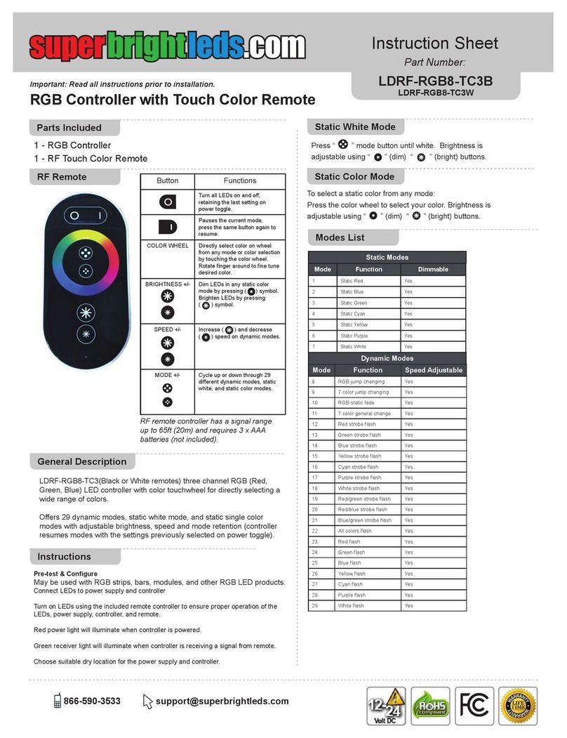
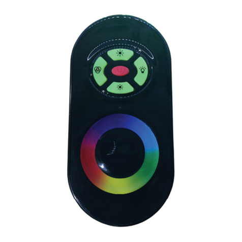
superbrightleds LDRF-RGB8-TC3B User manual

superbrightleds

superbrightleds LDRF-RGB8-TC3B User manual

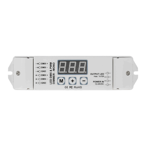
superbrightleds DMX-1CH-10A User manual

superbrightleds

superbrightleds DMX-1CH-10A User manual

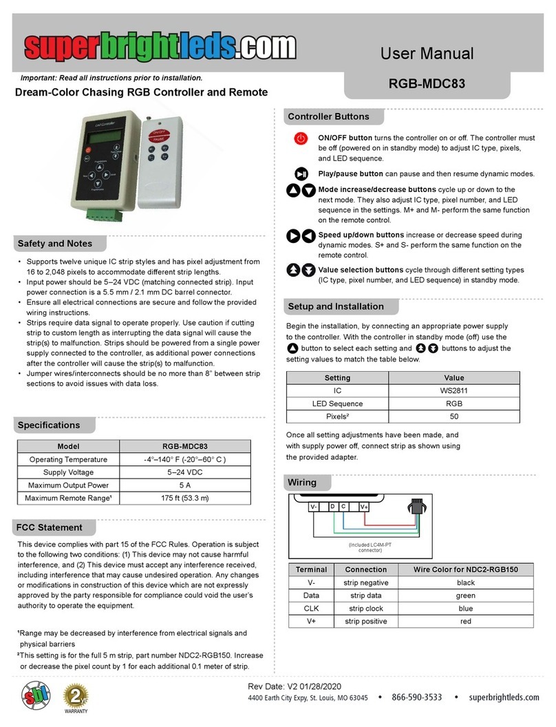
superbrightleds RGB-MDC83 User manual

superbrightleds

superbrightleds RGB-MDC83 User manual

superbrightleds GL-C-001W User manual

superbrightleds

superbrightleds GL-C-001W User manual

superbrightleds LDRF-RGB6-TC2B User manual

superbrightleds

superbrightleds LDRF-RGB6-TC2B User manual

superbrightleds WCBT-RGB10 User manual

superbrightleds

superbrightleds WCBT-RGB10 User manual

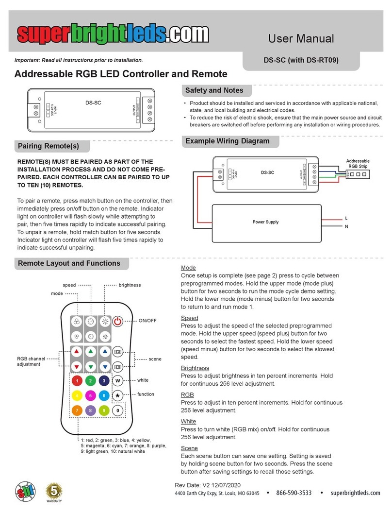
superbrightleds DS-SC User manual

superbrightleds

superbrightleds DS-SC User manual

superbrightleds Dream-Color RGB-DC83 User manual

superbrightleds

superbrightleds Dream-Color RGB-DC83 User manual

superbrightleds DS-CO4 User manual

superbrightleds

superbrightleds DS-CO4 User manual

Popular Controllers manuals by other brands

Aspar OSG HS user manual

Aspar

Aspar OSG HS user manual

LEGRAND Valena Next quick start guide

LEGRAND

LEGRAND Valena Next quick start guide

GOK FL 90-4 Assembly and operating instructions

GOK

GOK FL 90-4 Assembly and operating instructions

Leadshine Technology Co. 3DM683 user manual

Leadshine Technology Co.

Leadshine Technology Co. 3DM683 user manual

NetApp AltaVault Installation and setup instructions

NetApp

NetApp AltaVault Installation and setup instructions

Circutor FastComp 12rt quick start guide

Circutor

Circutor FastComp 12rt quick start guide

Agilent Technologies ETC 60 user guide

Agilent Technologies

Agilent Technologies ETC 60 user guide

Pixsys ATR 142 user manual

Pixsys

Pixsys ATR 142 user manual

Auber WS Series Operation & instruction manual

Auber

Auber WS Series Operation & instruction manual

ARAG BRAVO30 Series Use and maintenance

ARAG

ARAG BRAVO30 Series Use and maintenance

Seltron Regulus RCD2 Installation and maintenance manual

Seltron

Seltron Regulus RCD2 Installation and maintenance manual

HCFA HCA2 Series Hardware manual

HCFA

HCFA HCA2 Series Hardware manual

Beta Three EC4800 user manual

Beta Three

Beta Three EC4800 user manual

Drivecon Crane Commander Series instruction manual

Drivecon

Drivecon Crane Commander Series instruction manual

Mitsubishi Electric MELSEC Q Series user manual

Mitsubishi Electric

Mitsubishi Electric MELSEC Q Series user manual

Oki MSM9225B user manual

Oki

Oki MSM9225B user manual

Siemens SITRANS L Compact operating instructions

Siemens

Siemens SITRANS L Compact operating instructions

White International Icon Series user manual

White International

White International Icon Series user manual

manuals.online logo
manuals.online logoBrands
  • About & Mission
  • Contact us
  • Privacy Policy
  • Terms and Conditions

Copyright 2025 Manuals.Online. All Rights Reserved.