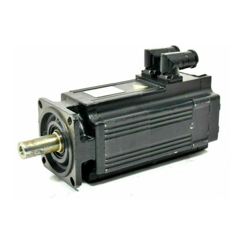
SEW-Eurodrive DR Series User manual

Gearmotors \ Industrial Gear Units \ Drive Electronics \ Drive Automation \ Services
AC Motors DR/DV/DT/DTE/DVE,
Asynchronous Servo Motors CT/CV
O
perating Instructions
A6.C01
Edition 08/2004
11291613 / EN

SEW-EURODRIVE – Driving the world

Operating Instructions – AC Motors DR / DV / DT / DTE / DVE / Asynchronous Servo Motors CT / CV
3
Contents
1 Important Notes................................................................................................. 4
2 Safety Notes ...................................................................................................... 5
3 Motor Design ..................................................................................................... 6
3.1 Basic structure of AC motors ....................................................................6
3.2 Nameplate, unit designation .....................................................................7
4 Mechanical Installation..................................................................................... 9
4.1 Before you begin.......................................................................................9
4.2 Preliminary work........................................................................................9
4.3 Installing the motor..................................................................................10
4.4 Installation tolerances .............................................................................11
5 Electrical Installation ...................................................................................... 12
5.1 Wiring notes............................................................................................12
5.2 Special aspects for operation with a frequency inverter.......................... 12
5.3 Special aspects of single-phase motors..................................................12
5.4 Improving the grounding (EMC)..............................................................13
5.5 Special aspects of torque motors and low-speed motors .......................13
5.6 Special aspects in switching operation ...................................................14
5.7 Environmental conditions during operation.............................................14
5.8 Connecting the motor..............................................................................15
5.9 Preparing motor sizes 56 and 63 – knockout..........................................16
5.10 Connecting DT56 motor...+/BMG............................................................16
5.11 Single-phase version ET56.....................................................................17
5.12 Connecting the motor using the IS plug connector.................................17
5.13 Connect the motor using plug connectors AB.., AD.., AM.., AS..............21
5.14 Connecting the motor using ASK1 plug connector .................................21
5.15 Connecting the brake..............................................................................23
5.16 Accessory equipment..............................................................................24
6 Startup.............................................................................................................. 28
6.1 Prerequisites for startup..........................................................................28
6.2 Altering the blocking direction on motors with a backstop ......................29
7 Malfunctions.................................................................................................... 31
7.1 Motor Malfunctions..................................................................................31
7.2 Brake problems.......................................................................................32
7.3 Malfunctions during operation with a frequency inverter.........................32
8 Inspection / Maintenance................................................................................ 33
8.1 Inspection and maintenance intervals.....................................................33
8.2 Preliminary work for motor and brake maintenance................................34
8.3 Inspection / maintenance on the motor ..................................................37
8.4 Inspection / maintenance of the BMG02 brake.......................................39
8.5 Inspection / maintenance of the brake BR03..........................................40
8.6 Inspection / maintenance for BMG05-8, BM15-62 brakes......................44
8.7 Inspection / maintenance of the BMG61/122 brake................................49
9 Technical Data................................................................................................. 52
9.1 Work done, braking torque BMG02.........................................................52
9.2 Information for ordering a replacement BMG02......................................52
9.3 Work done, working air gap, braking torques of BMG05-8, BR03.......... 53
9.4 Work done, working air gap, braking torques of BM15 - 62.................... 54
9.5 Operating currents ..................................................................................55
9.6 Permitted ball bearing types....................................................................59
9.7 Lubricant table for anti-friction bearings of SEW motors.........................59
10 Appendix.......................................................................................................... 60
10.1 Index of changes.....................................................................................60
10.2 Index .......................................................................................................61

4
Operating Instructions – AC Motors DR / DV / DT / DTE / DVE / Asynchrounos Servo Motors CT / CV
1Important Notes
Betriebsanleitung
1 Important Notes
Safety and
warning notes
Always follow the safety and warning instructions in these operating instructions!
You must adhere to the operating instructions to ensure:
• Trouble-free operation
• Fulfillment of any rights to claim under limited warranty
Consequently, read the operating instructions before you start operating the drive!
The operating instructions contain important information about servicing. Therefore,
keep the operating instructions close to the drive.
Waste disposal
Dispose of the following materials in accordance with the regulations in force:
•Iron
•Aluminum
• Copper
• Plastic
• Electronic components
Electrical hazard
Possible consequences: Severe or fatal injuries.
Hazard
Possible consequences: Severe or fatal injuries.
Hazardous situation
Possible consequences: Slight or minor injuries.
Harmful situation
Possible consequences: Damage to the drive and the environment.
Tips and useful information.

Operating Instructions – AC Motors DR / DV / DT / DTE / DVE / Asynchrounos Servo Motors CT / CV
5
2
Safety Notes
2 Safety Notes
Preface
The following safety notes are concerned with the use of motors. If using gearmotors,
also refer to the safety notes for gear units in the corresponding operating instructions.
Please also consider the supplementary safety notes in the individual sections of
these operating instructions.
General
information
During and after operation, motors and gearmotors have live and moving parts and their
surfaces may be hot.
All work related to transport, putting into storage, setting up/mounting,
connection, startup, maintenance and repair may only be performed by trained
personnel observing
• The corresponding detailed operating instructions and wiring diagrams
• The warning and safety signs on the motor/gearmotor
• The specific regulations and requirements for the system
• The national / regional regulations governing safety and accident prevention
Severe injuries and damage to property may result from
• Improper use
• Incorrect installation or operation
• Unauthorized removal of necessary protection covers or the housing
Designated use
These electric motors are intended for industrial systems. They fulfill the applicable
standards and regulations:
• Low voltage directive 73/23/EEC
Technical data and information about the permitted conditions can be found on the
nameplate and in the documentation.
It is essential to observe all the specified information!
Transportation
Inspect the shipment for damage as soon as you receive the delivery. Inform the
shipping company immediately. It may be necessary to preclude startup.
Tighten installed eyebolts. They are only designed for the weight of the
motor/gearmotor; do not attach any additional loads.
The installed lifting eyebolts comply with DIN 580. Observe the loads and regula-
tions specified in this standard. If the gearmotor is equipped with two suspension
eye lugs or lifting eyebolts, then both of the suspension eye lugs should be used
for transportation. In this case, the tension force vector of the slings must not
exceed a 45° angle in accordance with DIN 580.
Use suitable, sufficiently rated handling equipment if necessary. Remove any transpor-
tation fixtures prior to startup.
Installation /
assembly
Follow the instructions in the section "Mechanical Installation"!
Inspection /
maintenance
Follow the instructions in the section "Inspection and Maintenance"!

6
Operating Instructions – AC Motors DR / DV / DT / DTE / DVE / Asynchrounos Servo Motors CT / CV
3Basic structure of AC motors
Motor Design
3 Motor Design
3.1 Basic structure of AC motors
The following illustration is intended to explain the general structure. Its only purpose is
to facilitate the assignment of components to the spare parts lists. Discrepancies are
possible depending on the motor size and version!
02969AXX
10
7
11 12
1
20 44 41
16
42
36
35
37
32
13
22
132
131
112
111
129
130 115
113
119
123
116
118
117
2107 106
9
100
101
103
3
31
135 134
[1] Rotor, cpl. [31] Key [107] Oil-flinger ring [131] Sealing washer
[2] Circlip [32] Circlip [111] Gasket [132] Terminal box cover
[3] Key [35] Fan guard [112] Terminal box lower part [134] Screw plug
[7] Flanged end shield [36] Fan [113] Machine screw [135] Sealing washer
[9] Screw plug [37] V-ring [115] Terminal board
[10] Circlip [41] Equalizing ring [116] Terminal yoke
[11] Grooved ball bearing [42] Non drive-end
bearing shield [117] Hex head bolt
[12] Circlip [44] Grooved ball bearing [118] Lock washer
[13] Hex head screw (tie rod) [100] Hex nut [119] Machine screw
[16] Stator, cpl. [101] Lock washer [123] Hex head bolt
[20] Nilos ring [103] Stud [129] Screw plug
[22] Hex head bolt [106] Oil seal [130] Sealing washer

Operating Instructions – AC Motors DR / DV / DT / DTE / DVE / Asynchrounos Servo Motors CT / CV
7
3
Nameplate, unit designation
Motor Design
3.2 Nameplate, unit designation
Nameplate
Example: DFV 160 M4 /BM brake motor
Unit designation
Example: DR / DT / DV / DTE / DVE AC (brake) motors
Example: Serial number
03214BXX
DFV 132M2 / BM /TF / AMA1 / EV1T
Motor option: 5 V TTL incremental
encoder
Motor option: AMB1 plug connector
Motor option: TF thermistor sensor
Motor option: Brake
Size 132M and 2-pole
Flange-mounted motor
01. 3009818304. 0002. 99
Year number end digits of the year of manufacture (2-
digit)
Part number (4-digit)
Order number (10 digits)
Sales organization

8
Operating Instructions – AC Motors DR / DV / DT / DTE / DVE / Asynchrounos Servo Motors CT / CV
3Nameplate, unit designation
Motor Design
Nameplate
Example: CT90L4 / BMG / TF / ES1S servo brake motor
Unit designation
Examples: Servo (brake) motors CT / CV
Example: Serial number
51358BXX
CT90L4 BMG TF / ES1S
01.3410069302.0001.00
30.5
3000
10.5
103
345 7.9
B5 28 54 F
230~20 BGE 1.5
CFV 132M4 / BM / TF / EV1S
Motor option: Sine/cosine incremental encoder
Motor option: TF thermistor sensor
Motor option: Brake
Size 132M and 4-pole
Flange-mounted motor
01. 3009818304. 0002. 99
Year number end digits of the year of manufacture (2-
digit)
Part number (4-digit)
Order number (10 digits)
Sales organization

Operating Instructions – AC Motors DR / DV / DT / DTE / DVE / Asynchrounos Servo Motors CT / CV
9
4
Before you begin
Mechanical Installation
4 Mechanical Installation
4.1 Before you begin
The drive may
only be installed
if
• The entries on the nameplate of the drive and/or the output voltage of the frequency
inverter match the voltage supply system
• The drive is undamaged (no damage caused by transportation or storage)
• It is certain that the following requirements have been met:
– Ambient temperature between –20 °C and +40 °C1)
– No oil, acid, gas, vapors, radiation, etc.
– Installation altitude max. 1000 m above sea level
– Note the restrictions for encoders
– Special versions: Drive configured in accordance with the ambient conditions
4.2 Preliminary work
Motor shaft ends must be thoroughly cleaned of anti-corrosion agents, contamination or
similar (use a commercially available solvent). Do not allow the solvent to penetrate the
bearings or shaft seals – this could cause material damage!
Extendedstorage
of motors
• Please note the reduced grease utilization period of the ball bearings after storage
periods exceeding one year.
• Check whether the motor has absorbed moisture as a result of being stored for a long
time. Measure the insulation resistance to do this (measuring voltage 500 V).
The insulation resistance (→following figure) varies greatly depending on the
temperature! The motor must be dried if the insulation resistance is not adequate.
It is essential to comply with the safety notes in Section 2 during installation!
1) Minimum temperature for motors with backstop: –15 °C. Note that the temperature range of the gear unit
may also be restricted (→gear unit operating instructions)
01731AXX
100
10
1
0,1 020 40 60 80
[°C]
[M ]

10
Operating Instructions – AC Motors DR / DV / DT / DTE / DVE / Asynchrounos Servo Motors CT / CV
4Installing the motor
Mechanical Installation
Drying the motor
Heat up the motor
• with hot air or
• using an isolation transformer
– Connect the windings in series (→following figure)
– Auxiliary AC voltage supply max. 10 % of the rated voltage with max. 20 % of the
rated current
The drying process is finished when the minimum insulation resistance has been
attained.
Check the terminal box to see whether
• The inside is clean and dry
• The connections and fixing parts are free from corrosion
• The joint seals are OK
• The cable glands are sound, otherwise clean or replace them.
4.3 Installing the motor
The motor or gearmotor may only be mounted or installed in the specified mounting
position on a level and torsionally rigid support structure which is not subjected to
shocks.
Carefully align the motor and the driven machine to avoid placing any unacceptable
strain on the output shafts (observe permissible overhung load and axial thrust data!).
Do not butt or hammer the shaft end.
Use an appropriate cover to protect motors in vertical mounting positions from
objects or fluids entering (protection cowl C).
Ensure an unobstructed cooling air supply and that air heated by other apparatus cannot
be drawn in or reused.
Balance components for subsequent mounting on the shaft with a half key (motor shafts
are balanced with a half key).
Any condensation drain holes will be sealed by plastic plugs and should only be
opened when necessary; open condensation drain holes are not permitted, as
this would invalidate higher classes of enclosure.
If using brake motors with manual brake release, screw in either the hand lever (with
self-reengaging manual brake release) or the setscrew (with lockable manual brake
release).
Note the following for encoder mounting:
Foot-mounted motors CT/DT71, CT/DT90, CV/DV132M, CV/DV160L must be mounted
on supports because the radius of the cover is greater than the shaft height.
For foot-mounted (brake) motors sizes DTE90L and DVE132M, the shaft height corre-
sponds to the IEC standard motor of the next higher power level (100 mm or 160 mm).
The foot dimensions of DTE90, DVE180, and DVE225 motors differ from the IEC dimen-
sions; see Sec. "Dimension Sheet Notes" in the Gearmotors catalog.
01730AEN
Transformer

Operating Instructions – AC Motors DR / DV / DT / DTE / DVE / Asynchrounos Servo Motors CT / CV
11
4
Installation tolerances
Mechanical Installation
Installation in
damp locations
or in the open
If possible, arrange the terminal box so the cable entries are pointing downwards.
Coat the threads of cable glands and pocket caps with sealant and tighten them well –
then coat them again.
Seal the cable entry well.
Thoroughly clean the sealing surfaces of terminal boxes and terminal box covers prior
to reassembly; gaskets must be glued in on one side. Install new gaskets to replace
embrittled ones!
Restore the anticorrosive coating if necessary.
Check the enclosure.
4.4 Installation tolerances
Shaft end Flanges
Diameter tolerance in accordance with DIN 748
• ISO k6 at Ø ≤50 mm
• ISO m6 at Ø > 50 mm
• Center bore in accordance with DIN 332, shape
DR..
Centering shoulder tolerance in accordance with
DIN 42948
• ISO j6 at Ø ≤230 mm
• ISO h6 at Ø > 230 mm

12
Operating Instructions – AC Motors DR / DV / DT / DTE / DVE / Asynchrounos Servo Motors CT / CV
5Wiring notes
Electrical Installation
5 Electrical Installation
It is essential to comply with the safety notes in section 2 during installation!
Switch contacts in utilization category AC-3 to EN 60947-4-1 must be used for
switching the motor and the brake.
Using the wiring
diagrams
The motor must only ever be connected as shown in the wiring diagram included with
the motor. Do not connect or start up the motor if this wiring diagram is missing.
You can obtain the valid wiring diagram free of charge from SEW-EURODRIVE.
5.1 Wiring notes
Comply with the safety notes during installation.
Protecting brake
control systems
against
interference
Do not route brake cables alongside switched-mode power cables, as otherwise there
is a risk of disrupting brake control systems.
Switched-mode power cables include in particular:
– Output cables from frequency and servo controllers, converters, soft start units and
brake units
– Feeder cables for brake resistors and similar options
Protecting motor
protection
devices against
interference
Toprotect SEW motor protection devices (temperature sensorsTF, winding thermostats
TH) against interference:
– Route separately shielded feeder cables together with switched-mode power lines in
one cable
– Do not route unshielded feeder cables together with switched-mode power lines in
one cable
5.2 Special aspects for operation with a frequency inverter
When motors are powered from inverters, you must adhere to the wiring instructions
issued by the inverter manufacturer. It is essential to observe the operating instructions
for the frequency inverter.
5.3 Special aspects of single-phase motors
Bear in mind that SEW single-phase motors are supplied without accessory equipment
such as capacitors, starting relays or centrifugal switches (exception: ET56L4 →Sec.
"Single-phase version ET56"). Any parts you need must be obtained from your dealer
and connected according to the corresponding instructions and wiring diagrams.

Operating Instructions – AC Motors DR / DV / DT / DTE / DVE / Asynchrounos Servo Motors CT / CV
13
5
Improving the grounding (EMC)
Electrical Installation
5.4 Improving the grounding (EMC)
For improved, low-impedance grounding at high frequencies, we recommend using the
following connections with the DR/DV/DT AC motors:
• Sizes DT71 ... DV 132S: [1] M5x10 thread rolling screw and 2 serrated lock washers
to DIN 6798 in the stator housing.
• Sizes DV112M ... DV280: Screw and 2 serrated lock washers in the bore of the eye
bolt.
Thread size of the eye bolt:
– DV112 / 132S: M8
– DV132M ... 180L: M12
– DV200 ... 280: M16
5.5 Special aspects of torque motors and low-speed motors
Due to the design of torque motors and low-speed motors, very high induction voltages
may be generated when they are switched off. Consequently, SEW-EURODRIVE
recommends using the varistor circuit shown below for protection. The size of the varis-
tors depends, amongst other factors, on the starting frequency – note for project plan-
ning!
[1]
01732CXX
U
U
1
UU
V
1
W
1

14
Operating Instructions – AC Motors DR / DV / DT / DTE / DVE / Asynchrounos Servo Motors CT / CV
5Special aspects in switching operation
Electrical Installation
5.6 Special aspects in switching operation
When the motors are used in switching operation, possible interference of the switch-
gear must be excluded by ensuring suitable wiring. According to EN 60204 (electrical
equipment of machines), motor windings must have interference suppression to protect
the numerical or programmable logic controllers. As it is primarily switching operations
that cause interference, SEW-EURODRIVE recommends installing protective circuitry
in the switching devices.
5.7 Environmental conditions during operation
Ambient
temperature
The temperature range of -20 °C to +40 °C must be ensured unless specified otherwise
onthe nameplate. Motorsintended for use in higheror lower ambienttemperatures have
the appropriate designation on the nameplate.
Altitude
The maximum installation altitude of 1000 m above sea level must not be exceeded as
otherwise this causes a derating as specified in the following diagram.
Hazardous
radiation
Motors must not be subjected to hazardous radiation. Contact SEW-EURODRIVE if
necessary.
1000 2000 3000 4000 m
0.7
0.8
0.9
1.0
f
H

Operating Instructions – AC Motors DR / DV / DT / DTE / DVE / Asynchrounos Servo Motors CT / CV
15
5
Connecting the motor
Electrical Installation
5.8 Connecting the motor
Connecting the
motor via
terminal boxes
• According to the circuit diagram provided
• Check the line cross section
• Arrange terminal links correctly
• Screw connections and protective earth conductors on firmly
• In terminal boxes: Check winding connections and tighten them if necessary
Small connection
accessories
Note: In the case of motor sizes DR63 - DV132S, the small connection accessories
(connection nuts for feeder cables, terminal links, lock washer and washers) are
supplied in a bag. Depending on the type of terminal board, install the parts in accor-
dance with the figure below. In the connection type shown on the right in the figure
below, the second retaining nut, the lock washer and the washer are not used. The
external connection [6] can be installed directly or as a lug [4] below the connection disk
[5]. The tightening torque of the hex net in the figure on the right is:
•1.6Nm±20 % for M4
•2Nm±20 % for M5
In case of operation with electronic control units, it is essential to adhere to the
corresponding operating instructions / wiring diagrams!
50926AXX
1
2
3
4
5
6
7
8
Terminal stud
Lock washer
Connection disk
Motor terminal lead
Top nut
Washer
External connection
Bottom nut
1
2
3
4
5
6
Terminal stud
Hex nut with flange
Terminal link
Motor connection with Stocko connection
terminal
Connection disk
External connection
1
1
2
3
4
5
6
2
3
4
5
6
7
8
The asynchronous servomotors of the CT/CV series are supplied with connected
terminal links according to the nameplate.

16
Operating Instructions – AC Motors DR / DV / DT / DTE / DVE / Asynchrounos Servo Motors CT / CV
5Preparing motor sizes 56 and 63 – knockout
Electrical Installation
5.9 Preparing motor sizes 56 and 63 – knockout
Important: Wear safety glasses – danger of injury from fragments!
• Put on the terminal box cover and screw it into place
• Define which cable entries to open
• Open the cable entries
– with a chisel or similar (hold at an angle)
– by a light tap with a hammer
Caution – Do not knock through into the inside of the terminal box!
• Open the terminal box, remove the knockout cover if it has broken off
• Secure the cable screw fittings with the supplied lock nuts
5.10 Connecting DT56 motor...+/BMG
The motor has a star point with three fixed connection points in the winding overhang.
The supply system leads (L1, L2, L3) are connected to a spring cage terminal block [2]
in the terminal box [1]. The BMG02 brake is controlled using the BG1.2 brake rectifier
[3]. As an alternative, the brake can be controlled from the switch cabinet using BM
series rectifiers.
01733AXX
04861AXX
VW
U
TF TF
1
2
3

Operating Instructions – AC Motors DR / DV / DT / DTE / DVE / Asynchrounos Servo Motors CT / CV
17
5
Single-phase version ET56
Electrical Installation
5.11 Single-phase version ET56
The ET56 single-phase motor is supplied with a running capacitor that is mounted and
connected:
1~230 V, 50 Hz CB= 4 µF
1~230 V, 60 Hz CB= 4 µF
1~110 V, 60 Hz CB= 20 µF
5.12 Connecting the motor using the IS plug connector
The IS plug connector is supplied from the factory with its base fully wired-up, including
additional features such as a brake rectifier. The upper section of the IS connector is
included in the scope of delivery and must be connected as shown in the wiring diagram.
The IS plug connector has CSA approval up to 600 V. Note for application according to
CSA regulations: Tighten the M3 terminal screws to a torque of 0.5 Nm! See the
following table for American Wire Gauge (AWG) line cross sections!
Line cross
section
Make sure the type of line corresponds to the applicable regulations. The rated currents
are specified on the motor nameplate. The line cross sections that can be used are listed
in the following table.
No full-load startup is possible with the running capacitor alone! The single-
phase motor cannot be combined with a TF.
03075AXX
Without variable termi-
nal link With variable termi-
nal link Link cable Double assignment
(Motor and brake/SR)
0.25 - 4.0 mm20.25 - 2.5 mm2max. 1.5 mm2max. 1 x 2.5 and 1 x 1.5 mm2
23 - 12 # AWG 23 - 14 # AWG max. 16 # AWG max. 1 x 14 # and 1 x 16 # AWG

18
Operating Instructions – AC Motors DR / DV / DT / DTE / DVE / Asynchrounos Servo Motors CT / CV
5Connecting the motor using the IS plug connector
Electrical Installation
Wiring the upper
section of the
plug connection
• Loosen the housing cover screws
– Remove the housing cover
• Remove the screws from the upper section of the plug connector
– Remove the upper section of the plug connector from the cover
• Strip the insulation off the connection lead
– Strip about 9 mm insulation off the connecting leads
• Pass the cable through the cable gland
Wiring up as
shown in circuit
diagram DT82,
DT83
• Connect the lines as shown in the circuit diagram
– Tighten the clamping screws carefully!
• Install the plug connector (→Sec. "Installing the plug connector")
Wiring up as
shown in wiring
diagram DT81
For 댴/ 쑶startup:
• Connect with 6 lines
– Tighten the clamping screws carefully!
– Motor contactors in the switch cabinet
• Install the plug connector (→Sec. "Installing the plug connector")
For 댴or 쑶operation:
• Connect as shown in the wiring diagram
• Install the variable terminal link as shown in the following figures according to the
required motor operation (쑶or 댴)
• Install the plug connector (→Sec. "Installing the plug connector")
01734AXX 01735AXX

Operating Instructions – AC Motors DR / DV / DT / DTE / DVE / Asynchrounos Servo Motors CT / CV
19
5
Connecting the motor using the IS plug connector
Electrical Installation
Brake control
system BSR –
preparing the
variable terminal
link
For 댴operation:
On the 댴side of the variable terminal link as shown in the following figure: Remove only
the bare metal pin of the marked prong horizontally – touch guard!
For 쑶operation:
On the 쑶side of the variable terminal link as shown in the following figure: Completely
remove two prongs horizontally.
Wiringaccordingto
the DT81 wiring
diagram for
댴
or
쑶
operation with
double terminal
assignment
• At terminal point for double assignment:
– Connect the link cable
• When operation is as required:
– Insert the link cable in the variable terminal link
• Install the variable terminal link
• At terminal point for double assignment:
– Connect the motor lead above the variable terminal link
• Connect the other lines as shown in the wiring diagram.
• Install the plug connector (→Sec. "Installing the plug connector")
50429AXX
50430AXX
01738AXX

20
Operating Instructions – AC Motors DR / DV / DT / DTE / DVE / Asynchrounos Servo Motors CT / CV
5Connecting the motor using the IS plug connector
Electrical Installation
Installingtheplug
connector
The housing cover of the IS plug connector can be screwed onto the lower section of
the plug connector depending on the required position of the cable lead. The upper
section of the plug connector shown in the following figure must first be installed in the
housing cover so it will match the position of the lower section of the plug connector:
• Define the required mounting position
• Install the upper section of the plug connector into the housing cover in accordance
with the mounting position
• Close the plug connector
• Tighten the cable gland
Mounting position of the upper section of the plug connection in the housing cover
01739AXX
01740AXX
Other manuals for DR Series
4
This manual suits for next models
19
Table of contents
Other SEW-Eurodrive Servo Drive manuals

SEW-Eurodrive
SEW-Eurodrive CMP40 User manual

SEW-Eurodrive
SEW-Eurodrive CMP Series Operating instructions

SEW-Eurodrive
SEW-Eurodrive CM3C Series User manual

SEW-Eurodrive
SEW-Eurodrive CMP40 - 112 User manual

SEW-Eurodrive
SEW-Eurodrive CMP Series Operating instructions

SEW-Eurodrive
SEW-Eurodrive DFS Series User manual

SEW-Eurodrive
SEW-Eurodrive CMDV55M User manual

SEW-Eurodrive
SEW-Eurodrive CMP ELVCD User manual

SEW-Eurodrive
SEW-Eurodrive Movidrive MDX60B User manual

SEW-Eurodrive
SEW-Eurodrive CM3C Series User manual