Sinexcel SEA400/32-Y-E-P User manual

Contents
About the document
Symbol conventions
1. Safety
2. Description
3. Operation
4. Maintenance and cleaning
5. Troubleshooting
6. Cyber security
7. Warranty
8. Contact us
3
4
5
6
15
28
31
34
35
37
Version1.1

1)This user manual is only for the interstellar AC char-
ger series products (SEA400/32Y-E-P) developed and
produced by Sinexcel, and provides comprehensive
guidance for new energy vehicle users to use and main-
tain this charging device.
2)This manual will provide detailed product informa-
tion and operating instructions for users. Users should
read the contents of the manual carefully before use this
product and ensure that you understand all the instruc-
tions. Please store this manual in a safe place for easy
installation, operation, and maintenance personnel to
obtain and use.
3)The contents, pictures, logos, symbols, etc. used in
this manual are all owned by Sinexcel. Without written
authorization, it is forbidden to disclose, excerpt and
copy part or all of the contents of this manual (including
materials and publications).
4)The contents of this manual will be adjusted, revised
and updated according to product upgrades. Users
please refer to the actual product purchased.
About the
document
3
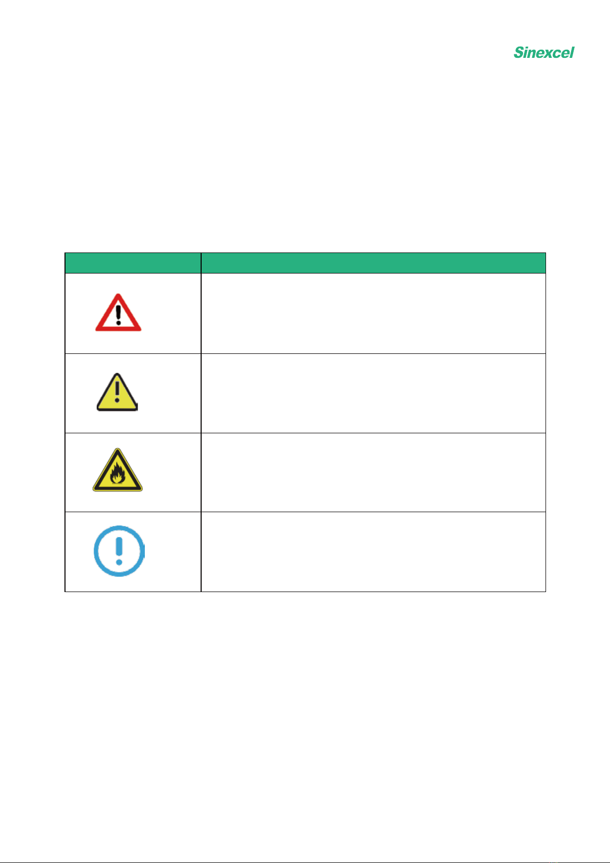
Symbol
Description
Warning
If you do not obey the instruction it might cause injury
or death.
Danger
Risk of electrocution
Caution of fire
Note
A note gives more details to make easily use.
4
Symbol conventions

1. Safety
5
1.1 General safety instructions
●This product is an integrated charger that can charge electric vehicles in indoor and outdoor areas.
●Please use and save the product information and accessories that are shipped with the device properly.
●If the user has any problems or failures during use, please consult the manufacture directly. During the
warranty period, if you privately find a third party or non-professional person for maintenance, any security
consequences will be borne by the user.
●The installation environment of charging equipment should be far away from fire and other dangerous
sources.
1.2 Safety instructions for use
●Please read the user manual carefully before use, and strictly follow the steps.
●Without the permission of the manufacturer, it is strictly forbidden for the user to disassemble the product
and other improper operations. The undesirable consequences caused by improper operation shall be borne
by the user.
●Do touch the charging plug or the charging socket of the electric vehicle. Keep the charging plug in a dry
state. Do not touch the charging plug with water.
●Do not to use the charging device when the connector is damaged or the insulation is damaged.
●Ensure that nothing remains in the charging plug and the charging socket on the vehicle side.
●Lock the door correctly after installation or maintenance operations.
In these situations, do not use the EVSE and contact to the manufacturer immediately :
●Damage on the enclosure
●Damage on the AC charger or connector
●Lighting hits the EVSE
●Accident or fire near the EVSE
●Water has entered the EVSE
If an emergency occurs during the operation
of this product, please press the emergency
button immediately. Do not use the emer-
gency button in non-emergency situations!

The emergency button is not a reset button so it is forbidden to press it in non-emergency situations.
After pressing it, the EVSE will stop charging immediately. If the emergency button is pressed by
mistake, please turn it gently in the direction of the arrow on the button to reset.
2. Description
2.1 General description
2.2.1 Overview of EVSE, outside
2.2 Overview
Interstellar is an AC charger supplies electricity to the EV. The product adopts DLM system and IMD
technology which makes strong charging performance and great product quality. It has multiple safety
protection functions and protection rating of IP65, suitable for indoor or outdoor use.
RFID area
logo
breathing light
emergency button
connector
6
162mm 406mm

2.2.2 Overview of EVSE, inside
Light board
Mainboard
Terminal block
RFID reader
Smart meter(optional)
Circuit breaker
Maintenance
cover
7
Part
Function
Maintenance cover For maintenance and operation of on&off
Circuit breaker For short circuit protection,overload protection and leakage
protection
Smart meter For metering
Mainboard To control the EVSE
RFID reader To start or stop charging session with the RFID card
Light board To show the operation status of EVSE
Terminal block To connect the cable of alternating current
input
from grid
Display
To show the operation status and parameter of EVSE
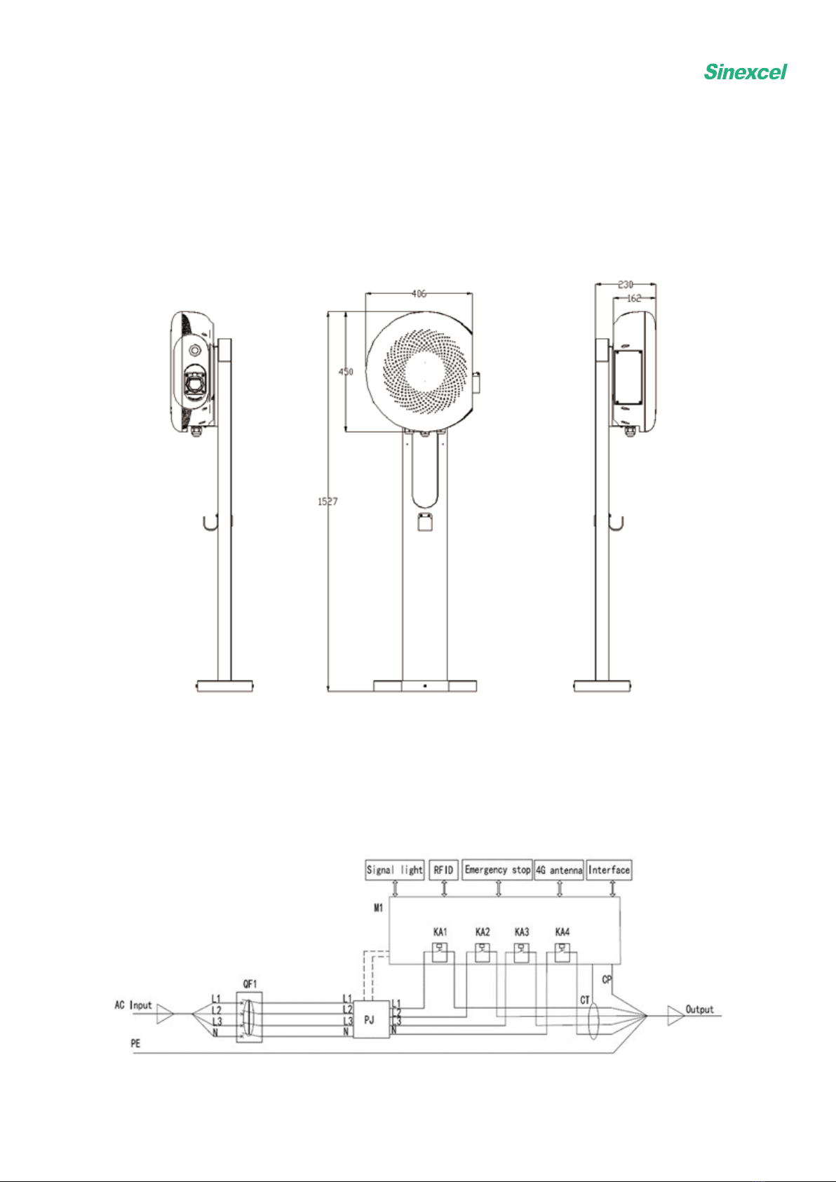
2.2.3 Pedestal
2.3 Working principle
8

2.4 Specification
9
Interstellar (Residential Use)
Rated Power
7kW
22kW
Input/Output
Voltage
Single-Phase 230V
Dimensions
W406*H450*D162
W406*H450*D162
Weight
5KG
7.5KG
Input/Output
Current
32A
Frequency
50Hz
Connector
IEC Type 2
Cable Length
3m(5m optional)
Charging Status
Information
LED
Authorization
Plug and Charge
Metering
MID Meter(optional)
Installation
Floor-mounted/Wall-mounted
Protection Function
Over current protection,over/under voltage
protection,over temperature protection,lighting
protection,short circuit protection,etc.
Protection Rating
IP65 /IK10
Operation
Temperature
-30 ℃-55 ℃
Operation Altitude
<2000m
Relative Humidity
5%-95%
RCD
Type A+DC 6mA
EMC
Class B
Certification
CE/TR25/TUV Mark/RCM
Color
Black/White/Silver
Three-Phase 400V

Floor-mounted/Wall-mounted
10
Interstellar (Commercial Use)
Rated Power
7kW
22kW
Input/Output
Voltage
Single -Phase 230V Three-Phase 400V
Dimensions
W406*H450*D162
W406*H450*D162
Weight
5KG
7.5KG
Input/Output
Current
32A
Frequency
50Hz
Connector
IEC Type 2
Cable Length
3m(5m optional)
Charging Status
Information
LED/Display(optional)
Authorization
NFC/RFID/Plug and Charge/APP(optional)
Metering
MID Meter(optional)
Communication
Method
LAN/4G/Wifi(optional)
Communication
Protocol
OCPP1.6J(can be updated to 2.0)
Installation
Protection Function
Protection Rating
IP65/IK10
Operation
Temperature
-30 ℃-55 ℃
Operation Altitude
<2000m
Relative Humidity 5%-95%
RCD
TypeA+DC 6mA
EMC
Class B
Certification
CE/TR25/TUV Mark/RCM
Color Black/White/Silver
Over current protection,over/under voltage
protection,over temperature protection,lighting
protection,short circuit protection,etc.
Note 1 DC 6mA has an automatically initiated test function, which is performed each time when
the relay is closed and at intervals not exceeding at least once a day.

No.
Parameter
Specification
Quantity
1
EVSE
Materials
:
PBT+PC
1
2
Wall-mounted template
L160*W299*D15mm
1
3
RFID card
2
4
Sabotage-proof hexalobular
socket screw
Stainless steel M4X10
6
5
Cable ties
1
6
Product manual &
installation manual
1
7
Product certification
1
8 Wrench
Stainless steel
T20
1
9
Expansion tube
¢6*30mm(PE)
4
10
Cross recessed pan head self-
drilling screw
Type C stainless steel
ST4.2*30mm
4
11
EVSE electrical drawings
Business/home version
1
2.5 Parts included in the delivery
Wall-mounted
Pedestal
11
No.
Parameter
Specification
Quantity
1
Pedestal
L390*W210*H1423mm
1
2
Sabotage -proof hexalobular
socket screw
Stainless steel
M4X10
5
3
Expansion anchor bolts
Stainless steel M8x80
4
4Plain washers
Stainless steel M8 plain
washers
4
5
Product manual & installation
manual
1
6
Wrench
Stainless steel
T20
1

2.6 Product model number
S E A
400/32-Y-E-P
12
S E A
230/32-Y-E-P

2.7 Standards
13
Interstellar is designed according to the European standard and meets the industrial standards in terms of
function and performance. The specific technical standards are shown in the table below.
NO.
Standard
number
Title
1IEC61851-1:2019
Electric vehicleconductive charging system. General
requirements
2
IEC62196-1:2014
Plugs, socket -outlets, vehicle connectors and vehicle inlets -
Conductive charging of electric vehicles- Part 1: General
requirements
3IEC62196-2:2017
Plugs, socket-outlets, vehicle connectors and vehicle inlets.
Conductive charging of electric vehicles.
4IEC62955-2018 Residual direct current detecting device (RDC-DD) to be used
for mode 3 charging of electric vehicles
5IEC60947-2:
2016
Low-voltage switchgear and control gear
-
Part 2: Circuit-
breakers
6EN 301 489 -1
V2.2.0(Draft)
EMC standard for radio equipment and services;
Part 1: Common technical requirements
7
EN 301 489 -1
V2.1.1(Final
draft)
EMC standard for radio equipment and services;
Part 1: Common technical requirements
8
EN 301 489-52
V1.1.0(Draft)
EMC
standard for radio equipment and services;
Part 52: Specific conditions for Cellular Communication
Mobile and portable (UE) radio and ancillary equipment
9EN 61000 -6-
1:2007
EMC -
Part 6 -1: Generic standards-
Immunity for residential,
commercial and light -industrial environments
10 EN 61000 -6-
3:2007+A1
EMC -
Part 6 - 3: Generic standards-
Emission standard for
residential, commercial and light -industrial environments

14
11
EN 62311:2008
Assessment of electronic and electrical equipment related to
human exposure restrictions for electromagnetic fields (0 Hz
-
300 GHz)
12
EN 62479:2010
Assessment of the compliance of low power electronic and
electrical equipment with the basic restrictions related to
human exposure to electromagnetic fields (10 MHz to 300
GHz)
13 EN 61851-1:2011
Electric vehicle conductive charging system- Part 1: General
requirements
14 EN 61851-
22:2002
Electric vehicle conductive charging system - Part 22: AC
electric vehicle charging station
15
EN 301511
V9.0.2
Global System for Mobile communications (GSM);
Harmonized EN for mobile stations in the GSM 900 and GSM
1800 bands covering essential requirements
16
EN 300 330
V2.1.1
Short Range Devices (SRD); Radio equipment in the frequency
range 9 kHz to 25 MHz and inductive loop systems in the
frequency range 9
kHz to 30 MHz

3.1 Prepare before operation
1)Ensure that there is no open flame around the EVSE and the surrounding space is not blocked
2)Ensure there is no damage on the cable.
3)Ensure that the EVSE is maintained regularly. Refer to section 4.
4)No need to set network or change any system settings following section 3.2/3.3.
3.2 Charging procedure
(EVSE with display)
1)Take the charge cable from the enclosure or the hunger installed on the pedestal (refer to section 3.5)
and connect to the EV.
2)After the connector is inserted correctly, the EVSE will be ready to charge.
3.2.1 Connect to the connector
3. Operation
15
2)The lights on the enclosure turn from dark to green, as shown in the figure below.
16
Authorize the use of EVSE by RFID card,password and operator APP.
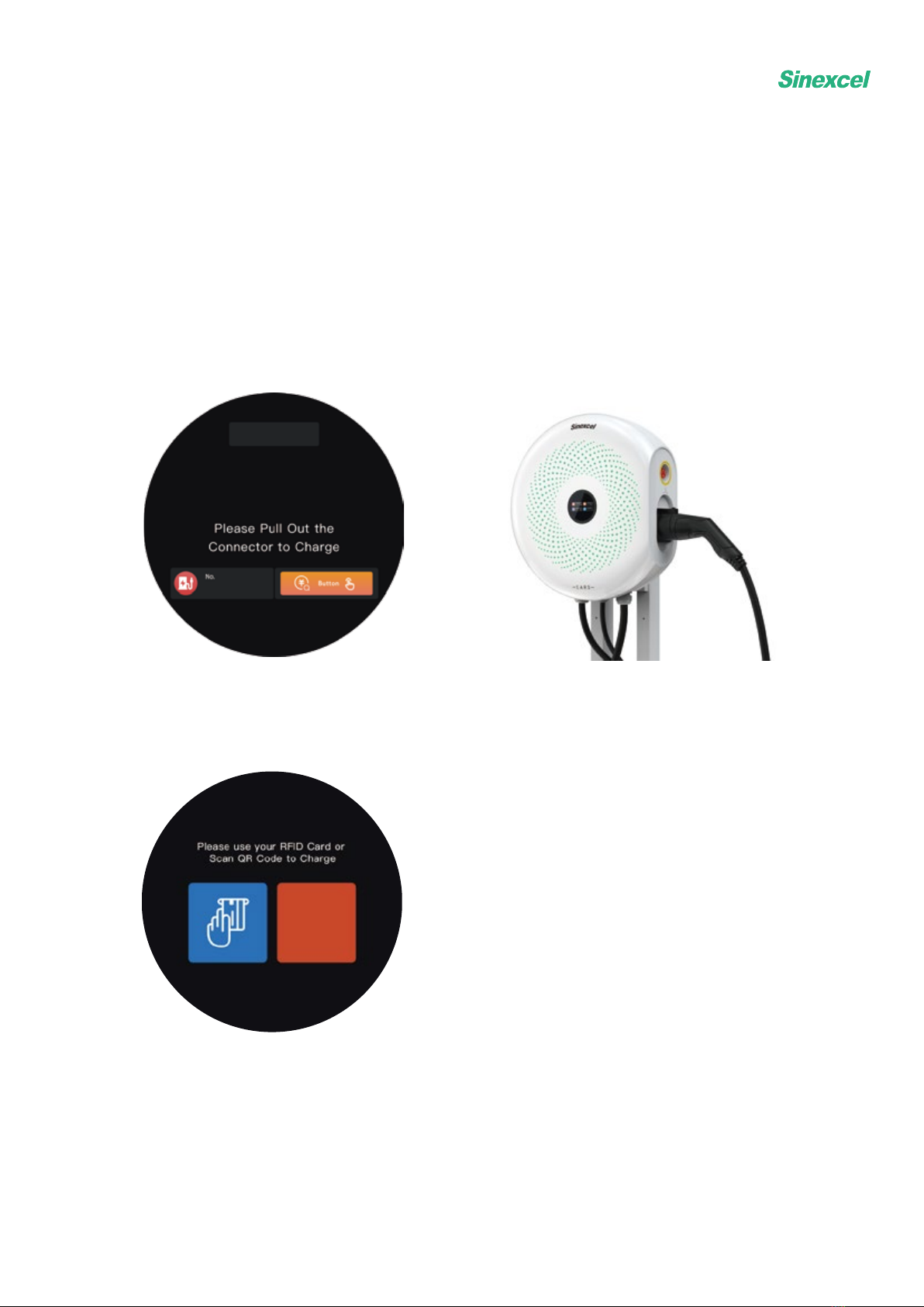
3.2.3 Prepare to charge screen
1)The display shows the standby screen as shown in the figure when the EVSE is in the idle status.
3.2.2 Standby screen
17
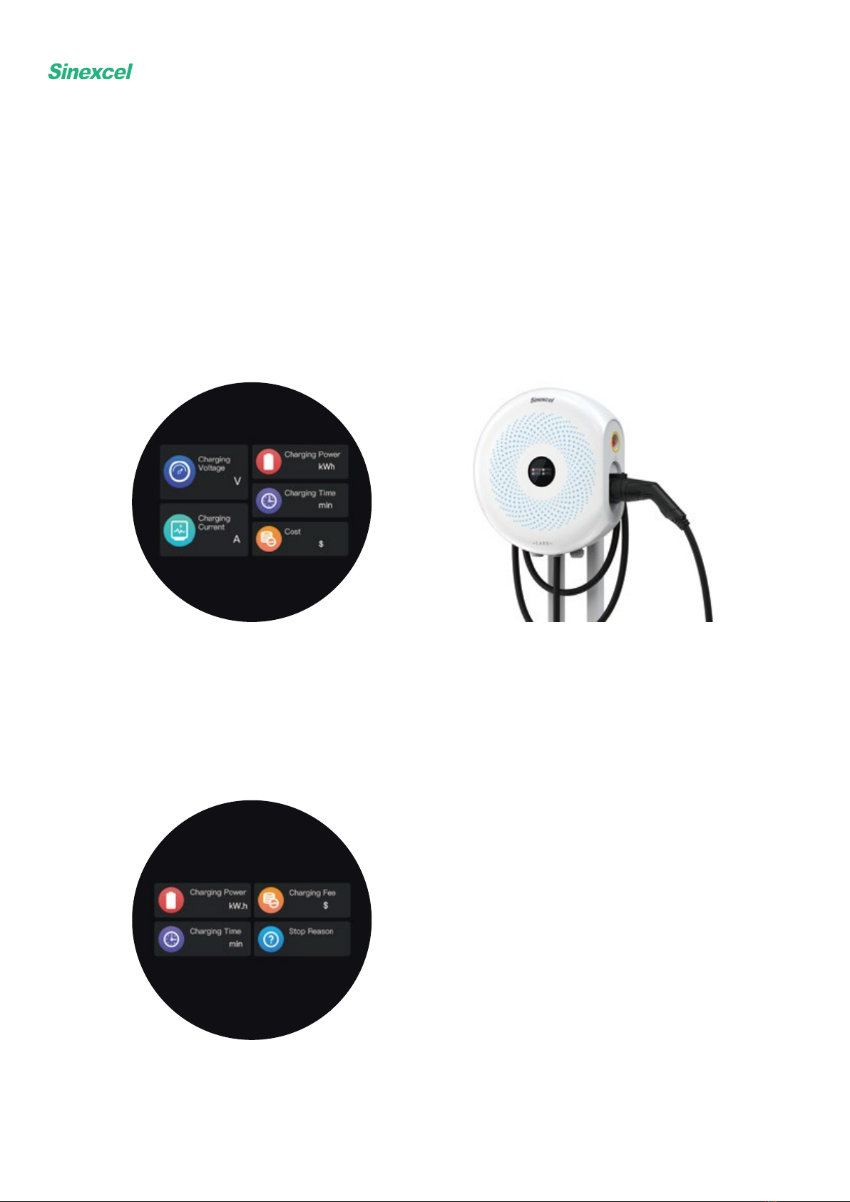
3.2.4 Start to charge screen
3.2.5 Stop charging screen
1)The interface jumps to charging information screen when the EVSE start to charge, as shown in the
figure below.
1)During the charging session, use RFID CARD、password and operator APP can stop charging. When
fully charged, the EVSE will automatically stop charging. In an emergency, it is able to cut off the power
by pressing the emergency stop button.
2)When the charging cycle is completed, the display as shown in the figure below.
2)During the charging session, the lights on the enclosure turn from green to blue, as shown in the figure
below.
3)When charging completed, lights on the enclosure turn from blue to dark. The user can pull-off the
connector and wrap it around the enclosure or put it back on the hunger.

18
3.3 Charging procedure
(EVSE without display)
3.3.1 Connect to the connector
1)Take out the connector from the enclosure or the hanger installed on the pedestal (refer to section 3.5)
and connect it to the EV.
2)After the connector is plugged in correctly, the EVSE will be ready to charge.
3.3.2 Start to charge
There are two ways to charge which depend on customer requirement.
- The first one is to tap the RFID CARD on the card reader to start charging.
- The second way is “Plug and Charge”. Just connect to the connector (refer to section3.2.1) will initiate
the charging process.
3.3.3 Stop charging
1)During the charging session, use RFID CARD、password、operator APP or unplug the connector will
stop charging. When fully charged, the EVSE will automatically stop charging too. In case of emergency,
pressing the emergency stop button will cut off the power.
2)When charging completed, blue light on the enclosure will be turned off. The user can unplug the
connector and return it.

3.4 Description of the display screens (optional)
3.4.1 How to enter the administrator interface
19
Tap this area twice.
The numeric keypad will show up. Then enter the password 123456 to get into the adminis-
trator interface.

20
3.4.2 How to set time
Choose manufacture setting.
Tap the Set Time button and the numeric keypad will show up. Enter the correct time in the
sequence of year, month, day, hour, minute and second (yyyy-MM-dd-HH-mm-ss). Please
note that dots should be entered between each data.
For example, for 2021/12/1 17:30:19, enter 21.12.1.17.30.19
This manual suits for next models
1
Table of contents
Other Sinexcel Batteries Charger manuals


