manuals.online logo
Brands
  1. Home
  2. •
  3. Brands
  4. •
  5. Fuji Electric
  6. •
  7. Inverter
  8. •
  9. Fuji Electric FRENIC-Mini 100 V Series User manual

Fuji Electric FRENIC-Mini 100 V Series User manual

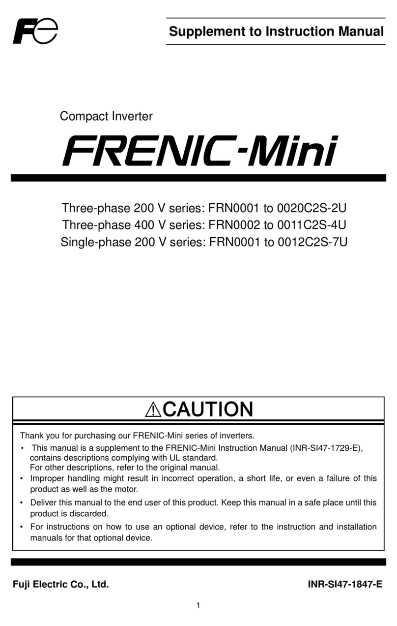
Instruction Manual
Supplement to Single-phase 100 V Input Series
Compact Inverter
Single-phase 100 V series: FRN0001 to 0005C2S-6U
Thank you for purchasing our FRENIC-Mini series of inverters.
• This manual is a supplement to the FRENIC-Mini Instruction Manual (INR-SI47-1729-E,
INR-SI47-1745-E). It describes the FRENIC-Mini output ratings (Inverter types FRN_ _ _
_C2S-6U) and basic connection. For other descriptions, refer to the original manual.
• Improper handling might result in incorrect operation, a short life, or even a failure of this
product as well as the motor.
• Deliver this manual to the end user of this product. Keep this manual in a safe place until this
product is discarded.
Fuji Electric Co., Ltd. INR-SI47-1839-E
Buy: www.ValinOnline.com | Phone 844-385-3099 | Email: [email protected]
Chapter 2 MOUNTING AND WIRING OF THE INVERTER
2.3.2 Terminal arrangement and screw specifications
(1) Arrangement of the main circuit terminals
Table 2.3 Main Circuit Terminals
Power
supply
voltage
Nominal
applied motor
(HP) Inverter type Terminal
screw size Tightening
torque
(lb-in) Refer to:
1/8 FRN0001C2S-6U
1/4 FRN0002C2S-6U
1/2 FRN0003C2S-6U
Single-
phase
100 V 1 FRN0005C2S-6U
M3.5 10.6 Figure C
2-3
2.3.3 Recommended wire sizes
Table 2.6 lists the recommended wire sizes. The recommended wire sizes for the main circuit
terminals at an ambient temperature of 50 C are indicated for two types of wire: HIV single wire (for
the maximum allowable temperature 75°C) (before a slash (/)) and IV single wire (for 60°C) (after a
slash (/)).
Table 2.6 Recommended Wire Sizes
*1
Recommended wire size (AWG)
Main circuit
Main circuit power input
[L1/R, L2/S, L3/T]
[L1/L, L2/N]
Grounding [ G]
Power supply voltage
Nominal
applied
motor
(HP) Inverter type
w/
DCR *2
w/o DCR
Inverter
output
[U, V, W] DCR
[P1, P (+)] Braking
resistor
[P (+), DB]
Control
circuit
1/8 FRN0001C2S-6U
1/4 FRN0002C2S-6U
1/2 FRN0003C2S-6U
14/14
Single-phase 100 V
1 FRN0005C2S-6U
14/14
14/12
14/14 *3 14/14 20
DCR: DC reactor
*1 Use crimp terminals covered with an insulated sheath or insulating tube.
*2 Wire sizes are calculated on the basis of input RMS current under the condition that the power supply
capacity and impedance are 50 kVA and 5%, respectively.
*3 Insert the DC reactor (DCR) in either of the primary power input lines. Refer to Chapter 10 for more
details.
2-5
Buy: www.ValinOnline.com | Phone 844-385-3099 | Email: [email protected]
2.3.5 Wiring for main circuit terminals and grounding terminals
Inverter output terminals, U, V, W and grounding terminal ( G)
1) Connect the three wires of the three-phase motor to terminals U, V, and W, aligning phases each other.
2) Connect the grounding wire of terminals U, V, and W to the grounding terminal ( G).
3) If the cable from the inverter to the motor is very long, a high-frequency current may be generated by
stray capacitance between the cables and result in an overcurrent trip of the inverter, an increase in
leakage current, or a reduction in current indication precision.
When a motor is driven by a PWM-type inverter, the motor terminals may be subject to surge voltage
generated by inverter element switching. If the motor cable (with 460 V series motors, in particular) is
particularly long, surge voltage will deteriorate motor insulation. To prevent this, use the following guidelines:
Inverters of 7.5 HP or above
Motor Insulation Level 1000 V 1300 V 1600 V
460 VAC Input Voltage 66 ft (20 m) 328 ft (100 m) 1312 ft (400 m)*
230 VAC Input Voltage 1312 ft (400 m)* 1312 ft (400 m)* 1312 ft (400 m)*
Inverters of 5 HP or below
Motor Insulation Level 1000 V 1300 V 1600 V
460 VAC Input Voltage 66 ft (20 m) 165 ft (50 m) 165 ft (50 m)*
230 VAC Input Voltage 328 ft (400 m)* 328 ft (100 m)* 328 ft (100 m)*
* For this case the cable length is determined by secondary effects and not voltage spiking.
When a motor protective thermal O/L relay is inserted between the inverter and the motor, the
thermal O/L relay may malfunction (particularly in the 460 V series), even when the cable
length is 165 ft (50 m) or less. To correct, insert a filter or reduce the carrier frequency. (Use
function code F26 (Motor sound).)
DC reactor terminals, P1 and P (+)
When wiring the inverter to the power supply of 50 kVA or more, be sure to connect an optional
DC reactor (DCR).
Otherwise, fire could occur.
2-9
Buy: www.ValinOnline.com | Phone 844-385-3099 | Email: [email protected]
Chapter 5 FUNCTION CODES
This chapter sets forth function codes whose setting ranges differ according to the input voltage for
the single-phase 100 V class series (FRN-_ _ _ _C2S-6U).
5.1 Function Code Tables
Code Name Data setting range Incre-
ment Unit Change
when
running
Data
copying
Default
setting Refer
to
page:
F05 Rated Voltage at Base
Frequency 1 0: Output a voltage in proportion to input
voltage
80 to 240: Output an AVR-controlled
voltage (Note 1)
160 to 500:Output an AVR-controlled
voltage (Note 2)
1 V N Y2 0 5-23
F06 Maximum Output
Voltage 1 80 to 240: Output an AVR-controlled
voltage (Note 1)
160 to 500:Output an AVR-controlled
voltage (Note 2)
1 V N Y2 200
F21 DC Braking 1
(Braking level) 0 to 100 (Note 3) 1 % Y Y 0 5-37
F44 Current Limiter (Level) 20 to 180 (Note 3) 1 % Y Y 160 5-42
P63 Permanent magnet
synchronous motor *1
(Induced voltage)
0 (Disable PMSM),
80 to 240 (Note 1)
160 to 500 (Note 2)
1 V N Y2
0
–
H15 Restart Mode after
Momentary Power
Failure
(Continuous running
level) *1
200 to 300 (Note 1)
400 to 600 (Note 2) 1 V Y Y2 235
470 –
H27 Thermistor for Motor
(Level) *2 0.00 to 5.00 0.01 V Y Y 1.6 –
H51 Non-linear V/f Pattern 1
(Voltage) 0 to 240: Output an AVR-controlled voltage
(Note 1)
0 to 500: Output an AVR-controlled voltage
(Note 2)
1 V N Y2 0 5-23
H53 Non-linear V/f Pattern 2
(Voltage) 0 to 240: Output an AVR-controlled voltage
(Note 1)
0 to 500: Output an AVR-controlled voltage
(Note 2)
1 V N Y2 0
A03 Rated Voltage at Base
Frequency 2 0: Output a voltage in proportion to input
voltage
80 to 240V: Output an AVR-controlled
voltage (Note 1)
160 to 500V: Output an AVR-controlled
voltage (Note 2)
1 V N Y2 0 –
A04 Maximum Output
Voltage 2 80 to 240V: Output an AVR-controlled
voltage (Note 1)
160 to 500V: Output an AVR-controlled
voltage (Note 2)
1 V N Y2 200 –
A10 DC Braking 2
(Braking level) 0 to 100 (Note 3) 1 % Y Y 0 –
J68 Braking Signal
(Brake OFF current) 0 to 200 (Note 3) 1 % Y Y 100 –
*1 The PMSM drive is available in the ROM version 0500 or later.
*2 In the ROM version 0800 or later, the factory default is changed from 0.16 to 1.6.
(Note 1) For the three-phase 200 V, single-phase 200 V, and single-phase 100 V class series
(Note 2) For the three-phase 400 V class series
(Note 3) The reference current for the single-phase 100 class series is as listed below.
Nominal applied motor (HP) 1/8 1/4 1/2 1
Reference current (A) 0.8 1.5 3.0 5.0
5-2
Buy: www.ValinOnline.com | Phone 844-385-3099 | Email: [email protected]
TableA Fuji Standard Motor Parameters
Fuji's standard
torque boost
(%)
Nominal rated
current of
Fuji standard motor
(A)
Nominal rated
capacity of
Fuji standard motor
(kW)
Power
supply
voltage
Nominal
applied
motor
(HP)
Inverter type
Function code
F09/A05 Function code
F11/A07/E34/E37 Function code
P02/A16
1/8 FRN0001C2S-6U 8.4 0.68 0.10
1/4 FRN0002C2S-6U 8.4 1.40 0.20
1/2 FRN0003C2S-6U 7.1 2.00 0.40
Single-
phase
100 V
1 FRN0005C2S-6U 6.8 3.00 0.75
5-20
5.2 Details of Function Codes
F20 to F22
H95
DC Braking 1 (Braking starting frequency, Braking level, and Braking time)
DC Braking (Braking response mode)
Braking level (F21) for single-phase 100 V class series
The braking level setting should be calculated from the DC braking level I
DB
(A)
based on the reference current I
ref
(A), as shown below.
100
(A)
(A)
=(%)Setting
ref
DB
I
I
(Example) Setting the braking level I
DB
at 4.2 Amp (A) for 1 HP standard motors
84100
(A)5.0 (A)4.2
=(%)Setting
Nominal applied motor (HP) 1/8 1/4 1/2 1
Reference current Iref (A) 0.8 1.5 3.0 5.0
5-37
Buy: www.ValinOnline.com | Phone 844-385-3099 | Email: [email protected]
F30
F31
Analog Output [FMA] (Voltage adjustment)
Analog Output [FMA] (Function)
Voltage adjustment (F30) for single-phase 100 V class series
Outputting the output current in an analog format (FMA) (F31 = 2)
The analog output terminal [FMA] outputs 10 V, that is, 200% of the reference
current I
ref
(A), supposing the output gain selected with F30 as 100%. Therefore, to
adjust the output voltage, you need to set the output gain at terminal [FMA] (F30)
based on the conversion result obtained by the following expression:
Conversion formula for calculating the output gain which is required for
outputting the voltage V (V) via terminal [FMA] when current I(A) flows across
the inverter
100
(V)10(V)V
(A)
(A)
2=gainOutput
ref
I
I
I
ref
(A): Reference current (A)
The reference current is given in the table for F20 to F22 on page 5-37.
According to the conversion result, the output voltage to terminal [FMA] can be
calculated as shown below.
(V)10
100 (F30)gainOutput
(A)2(A)
=(V)voltageoutputAnalog
ref
I
I
(Example) Outputting analog voltage 8V for 1 HP standard motors when the
inverter output current is 4.2A
190.4100
(V)10(V)8
(A)4.2 (A)5.0
2=gainOutput
7.98(V)10
100
190
(A)5.02(A)4.2
=(V)voltageoutputAnalog
Reference table
To output analog 10 V at 200% of the rated current of any of the single-phase 100 V
class series of inverters, set the output gain at terminal [FMA] (F30) as listed below.
Nominal applied motor (HP) 1/8 1/4 1/2 1
Output gain to be set to F30 (%) 114 107 120 119
Function (F31)
F31 specifies what is output to analog output terminal [FMA].
Data for
F31 [FM] output Function
(Monitor the following) Meter scale
(Full scale at 100%)
3 Output voltage Output voltage
(RMS) of the inverter
250 V for three-phase 200 V,
single-phase 200 V, and single-phase
100 V class series
500 V for three-phase 400 V class series
9 DC link bus
voltage DC link bus voltage of
the inverter
500 V for three-phase 200 V,
single-phase 200 V, and single-phase
100 V class series
1000 V for three-phase 400 V class
series
5-40
Buy: www.ValinOnline.com | Phone 844-385-3099 | Email: [email protected]
F43, F44
Current Limiter (Mode selection, Level)
Level (F44) for single-phase 100 V class series
The limiting level setting should be calculated from the current limiting level I
limit
(A)
based on the reference current I
ref
(A), as shown below.
100
(A)
(A)
=(%)Setting
ref
limit
I
I
(Example) Setting the current limiting level I
limit
at 4.2 A for 1 HP standard motors
84100
(A)5.0 (A)4.2
=(%)Setting
The reference current is given in the table for F20 to F22 on page 5-37.
5-42
F50, F51
Electronic Thermal Overload Protection for Braking Resistor
(Discharging capability and Allowable average loss)
External Braking Resistors
Standard models
Braking resistor Continuous braking
(100% braking torque) Intermittent braking
(Period: 100 s or less)
Power
supply
voltage Inverter type Type Qty.
Resistance
() Discharging
capability
(kWs)
Braking
time
(s)
Allowable
average loss
(kW)
Duty
(%ED)
FRN0003C2S-6U 9 0.044 22
Single-
phase
100 V FRN0005C2S-6U DB0.75-2 1 100 17 45 0.068 18
10% ED models
Braking resistor Continuous braking
(100% braking torque) Intermittent braking
(Period: 100 s or less)
Power
supply
voltage Inverter type Type Qty.
Resistance
() Discharging
capacity
(kWs)
Braking
time
(s)
Allowable
average
loss (kW)
Duty
(%ED)
FRN0003C2S-6U 250 37
Single-
phase
100 V FRN0005C2S-6U DB0.75-2C 1 100 50 133 0.075 20
5-43
Buy: www.ValinOnline.com | Phone 844-385-3099 | Email: [email protected]
Chapter 8 SPECIFICATIONS
8.1 Standard Models
8.1.4 Single-phase 100 V class series
Item Specifications
Type (FRN_ _ _ _C2S-6U) 0001 0002 0003 0005
Nominal applied motor (HP) *1 1/8 1/4 1/2 1
Rated capacity (kVA) *2 0.26 0.53 0.95 1.6
Rated voltage (V) *3 Three-phase, 200 to 240 V (with AVR function)
Rated current (A) 0.7 1.4 2.5 4.2
Overload capability 150% of rated output current for 1 min or
200% of rated output current for 0.5 s
Output Ratings
Rated frequency (Hz) 50,60 Hz
Phases, voltage, frequency Single-phase, 100 to 120 V, 50/60 Hz
Voltage and frequency
variations Voltage: +10 to -10%, Frequency: +5 to -5%
(w/ DCR) 2.2 3.8 6.4 12.0
Rated current (A)
*6 (w/o DCR) 3.6 5.9 9.5 16.0
Input Ratings
Required power supply
capacity (kVA) *7 0.3 0.5 0.7 1.3
Torque (%) *8 150 100
DC braking Braking starting frequency*9: 0.0 to 60.0 Hz,
Braking time: 0.0 to 30.0 s, Braking level: 0 to 100%
Braking
Braking transistor -- Built-in
Applicable safety standards UL508C (under application)
Enclosure IP20 (IEC 60529:1989), UL open type (UL50)
Cooling method Natural cooling
Mass (lbs.) 1.5 1.5 1.8 2.9
*1 Fuji 4-pole standard motors
*2 Refers to the rated capacity assuming the rated output voltage as 220 V.
*3 The inverter cannot output voltage that is 2 or more times its rated voltage.
*6 Refers to the estimated value to apply when the power supply capacity is 50 kVAand the inverter is connected to
the %X = 5% power supply.
*7 Refers to the value to apply when a DC reactor (DCR) is used.
*8 Refers to the average braking torque to apply when the motor running alone decelerates from 60 Hz with theAVR
control being OFF. (It varies with the efficiency of the motor.)
*9 Available only for induction motor drive.
(Note) When driven by 100 VAC, the single-phase 100 V class series of inverters limit their shaft output and
maximum output torque as listed below. This is to prevent their output voltage from decreasing when
load is applied.
Shaft output (%) Maximum torque (%)
w/o DC reactor (DCR) 90 150
w/ DC reactor (DCR) 85 120
8-3a
Buy: www.ValinOnline.com | Phone 844-385-3099 | Email: [email protected]
8.3 Terminal Specifications
8.3.2 Connection diagram in operation by external signal inputs
(Note 1) Install a recommended molded case circuit breaker (MCCB) or a residual-current-operated
protective device (RCD)/earth leakage circuit breaker (ELCB) (with overcurrent protection) in the
primary circuit of the inverter to protect wiring. Do not use an MCCB or RCD/ELCB whose
capacity exceeds the recommended rated current.
(Note 2) A magnetic contactor (MC) should, if necessary, be mounted independent of the MCCB or ELCB
to cut off the power fed to the inverter. Refer to page 9-1 for details. MCs or solenoids that will be
installed close to the inverter require surge absorbers to be connected in parallel to their coils.
(Note 3) When connecting a DC reactor (option), remove the jumper bar from terminals [P1] and [P+].
Note that the terminal assignment of single-phase 100 V class series of inverters differs that of
the above diagram. For details about the terminal assignment, see Figure 10.1 "Connection
Diagram of DC reactor (DCR)" in Chapter 10.
(Note 4) The THR function can be used by assigning "9" (External alarm) to any of terminals [X1] to [X3],
[FWD] or [REV] (function code E01 to E03, E98, or E99). For details, refer to Chapter 5.
(Note 5) Frequency can be set by connecting a frequency setting device (external potentiometer) between
terminals [11], [12], and [13] instead of inputting voltage signal (0 to +10 VDC or 0 to +5 VDC)
between terminals [12] and [11].
(Note 6) For the wiring of the control circuit, use shielded or twisted wires. When using shielded wires,
connect the shields to earth. To prevent malfunction due to noise, keep the control circuit wiring
away from the main circuit wiring as far as possible (recommended: 10 cm or longer), and never
set them in the same wire duct. When crossing the control circuit wiring with the main circuit
wiring, set them at right angles.
(Note 7) It is recommended for noise control that 3-phase, 4-wire cable be used for the motor wiring.
Connect grounding wires of the motor to the grounding terminal G on the inverter.
8-7
* With a built-in terminating
resistor switch
Buy: www.ValinOnline.com | Phone 844-385-3099 | Email: [email protected]
8.4 External Dimensions
8.4.1 Standard models
Unit: inch [mm]
Dimensions
inch [mm]
Power
supply
voltage Inverter type DD1 D2
Single-
phase
100 V FRN0005C2S-6U 5.47
[139] 3.90
[99] 1.57
[40]
Dimensions
inch [mm]
Power
supply
voltage Inverter type DD1D2
FRN0001C2S-6U
FRN0002C2S-6U 3.94
[100] 0.39
[10]
Single-
phase
100 V FRN0003C2S-6U 4.53
[115]
3.54
[90] 0.98
[25]
8-9
Buy: www.ValinOnline.com | Phone 844-385-3099 | Email: [email protected]
8.5 Protective Functions
Name Description
LED
monitor
displays
Alarm
output
[30A,B,C]
During
acceleration
During
deceleration
Overvoltage
protection
he inverter stops the inverter output upon
detecting an overvoltage condition (400 VDC for
three-phase 200 V, single-phase 200 V, and
single -phase 100 V class series; 800 VDC for
three -phase 400 V class series) in the DC link
bus.
his protection is not assured if excess AC line
voltage is applied inadvertently.
During running
at constant
speed
(Stopped)
Yes
Undervoltage
protection
Stops the inverter output when the DC link bus voltage drops below
the undervoltage level (200 VDC for three-phase 200 V,
single-phase 200 V, and single-phase 100 V class series; 400 VDC
for three-phase 400 V class series).
However, if data "4 or 5" is selected for F14, no alarm is output even
if the DC link bus voltage drops.
Yes
(Note)
(Note) No alarm output depending upon the data setting of the function code.
8-11
Buy: www.ValinOnline.com | Phone 844-385-3099 | Email: [email protected]
Chapter 9 LIST OF PERIPHERAL EQUIPMENT AND OPTIONS
Name of
peripheral
equipment Function and application
Main peripheral equipment
Molded case
circuit breaker
(MCCB)
Residual-current-
operated
protective device
(RCD)
/Earth leakage
circuit breaker
(ELCB)*
*with overcurrent
protection
MCCBs are designed to protect the power circuits between the power control
board and inverter’s main terminals (L1/R, L2/S and L3/T for three-phase
power, L1/L and L2/N for single-phase power) from overload or short-circuit
which in turn prevents secondary disasters caused by the inverter
malfunctioning.
RCDs/ELCBs function in the same way as MCCBs. Use the MCCBs and
RCDs/ELCBs that satisfy the recommended rated current listed below.
Recommended rated current (A) of
MCCB and RCD/ELCB
Power
supply
voltage
Nominal
applied
motor
(HP)
Inverter type w/ DC reactor w/o DC reactor
1/8 FRN0001C2S-6U 5
1/4 FRN0002C2S-6U 5 10
1/2 FRN0003C2S-6U 10 15
Single-
phase
100 V 1 FRN0005C2S-6U 15 20
When connecting the inverter to the power supply, add a recommended
molded case circuit breaker (MCCB) or a residual-current-operated
protective device (RCD)/earth leakage circuit breaker (ELCB)* in the path of
power supply. Do not use the devices with the rated current out of the
recommended range. *With overcurrent protection
Fire could occur.
Select the MCCB or RCD/ELCB with appropriate rated current and breaking
capacity according to the power supply capacity.
9-1
Buy: www.ValinOnline.com | Phone 844-385-3099 | Email: [email protected]
Chapter 10 APPLICATION OF DC REACTORS (DCRs)
Since the "Japanese Guideline for Suppressing Harmonics in Home and General-purpose
Appliances" issued by the Ministry of International Trade and Industry (Currently the Ministry of
Economy, Trade and Industry) was revised in January 2004, the general-purpose inverters have no
longer been subject to the guideline. Individual inverter manufacturers have voluntarily employed
harmonics suppression measures. It is recommended that DC reactors (DCRs) specified in Table
10.1 be connected to the FRENIC-Mini series of inverters.
Table 10.1 List of DC Reactors (DCRs)
Power
supply
voltage Nominal applied
motor (HP) Applicable inverter type DCR type
1/8 FRN0001C2S-6U DCR2-0.75
1/4 FRN0002C2S-6U DCR2-1.5
1/2 FRN0003C2S-6U DCR2-2.2
Single-
phase
100 V 1 FRN0005C2S-6U DCR2-3.7
FRENIC-Mini
L1/L
L2/N
U
V
W
G
P1
DCR
P1 P(+) P(+)
Power
supply Motor
Note: Remove the capacitor
connected between terminals
P1 and P(+) for DCR.
M
3
G
Figure 10.1 Connection Diagram of DC Reactor (DCR) (For single-phase 100 V)
10-1
Buy: www.ValinOnline.com | Phone 844-385-3099 | Email: [email protected]
Chapter 11 COMPLIANCE WITH STANDARDS
11.1 Compliance with UL Standards and Canadian Standards (cUL certification)
11.1.1 General
Originally, the UL standards were established by Underwriters Laboratories, Inc. as private criteria
for inspections/investigations pertaining to fire/accident insurance in the USA. Later, these standards
were authorized as the official standards to protect operators, service personnel and the general
populace from fires and other accidents in the USA.
cUL certification means that UL has given certification for products to clear CSA Standards. cUL
certified products are equivalent to those compliant with CSA Standards.
11.1.2 Considerations when using FRENIC-Mini in systems to be certified by UL and cUL
To use the FRENIC-Mini series of inverters as a part of UL Standards or CSA Standards (cUL
certified) certified product, refer to the guidelines given below.
Conformity to UL standards and Canadian standards (cUL certification)
If installed according to the guidelines given below, inverters marked with UL/cULare considered as
compliant with the UL and CSA (cUL certified) standards.
Integral solid state short circuit protection does not provide branch circuit protection. Branch
circuit protection must be provided in accordance with the National Electrical Code and any
additional local codes.
1. Solid state motor overload protection (motor protection by electronic thermal overload relay)
is provided in each model.
Adjust function codes F10 to F12 and H89 to set the protection level.
2. Connect the power supply satisfying the characteristics shown in the table below as an input
power supply of the inverter. (Short circuit rating)
3. Use 75 C Cu wire only.
4. Use Class 1 wire only for control circuits.
Short circuit rating
When protected by class J fuses, suitable for use on a circuit capable of delivering not more
than B rms symmetrical amperes, A volts maximum.
Power
supply
voltage Inverter type Power supply max. voltage
A (Volts) Power supply current
B (Amperes)
FRN0001C2S-6U
FRN0002C2S-6U
FRN0003C2S-6U
Single-
phase
100V FRN0005C2S-6U
120 VAC 65,000 A or less
11-1
Buy: www.ValinOnline.com | Phone 844-385-3099 | Email: [email protected]
Conformity to UL standards and Canadian standards (cUL certification) (Continued)
5. Install UL certified fuses rated 600 Vac between the power supply and the inverter, referring to
the table below.
*1 Denotes the relay contact terminals for [30A], [30B] and [30C].
*2 Denotes control terminals except for [30A], [30B] and [30C].
*3 Values in [ ] mean the size (AWG) of Grounding wires if exist.
6. To comply with CSA for 100 VAC input models, transient surge suppression shall be
installed on the line side of this equipment and shall be rated 120 V (phase to ground), 120 V
(phase to phase), suitable for overvoltage category 3, and shall provide protection for a rated
impulse withstand voltage peak of 2.5 kV.
7. Maximum surrounding air temperature rating of 50ºC.
Required torque
Ib-in (N·m) Wire size
AWG or kcmil (mm
2
)
Control circuit Control circuit
Power
supply
voltage Inverter type Main
terminal *1
TERM1
*2
TERM2-1
TERM2-2
*3
Main
terminal *1
TERM1
*2
TERM2-1
TERM2-2
Class J fuse
current (A)
FRN0001C2S-6U 6
FRN0002C2S-6U 10
FRN0003C2S-6U 15
Single-
phase
100 V FRN0005C2S-6U
10.6
(1.2) 3.5
(0.4) 1.8
(0.2) 14 20
(0.5)
30
11-2
Buy: www.ValinOnline.com | Phone 844-385-3099 | Email: [email protected]
Compact Inverter
Instruction Manual
Supplement to Single-phase 100 V Input Series
First Edition, March 2014
Fuji Electric Co., Ltd.
The purpose of this instruction manual is to provide accurate information in handling, setting up and
operating of the FRENIC-Mini series of inverters. Please feel free to send your comments regarding
any errors or omissions you may have found, or any suggestions you may have for generally
improving the manual.
In no event will Fuji Electric Co., Ltd. be liable for any direct or indirect damages resulting from the
application of the information in this manual.
Buy: www.ValinOnline.com | Phone 844-385-3099 | Email: [email protected]

This manual suits for next models

4

Other Fuji Electric Inverter manuals

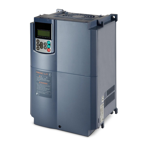
Fuji Electric Frenic lift How to use

Fuji Electric

Fuji Electric Frenic lift How to use

Fuji Electric FRENIC5000G11S Series Instruction manual

Fuji Electric

Fuji Electric FRENIC5000G11S Series Instruction manual

Fuji Electric FRENIC-AQUA series User manual

Fuji Electric

Fuji Electric FRENIC-AQUA series User manual

Fuji Electric FRENIC-Multi User manual

Fuji Electric

Fuji Electric FRENIC-Multi User manual

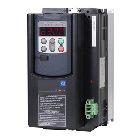
Fuji Electric FRENIC-Lift 400 V Series How to use

Fuji Electric

Fuji Electric FRENIC-Lift 400 V Series How to use

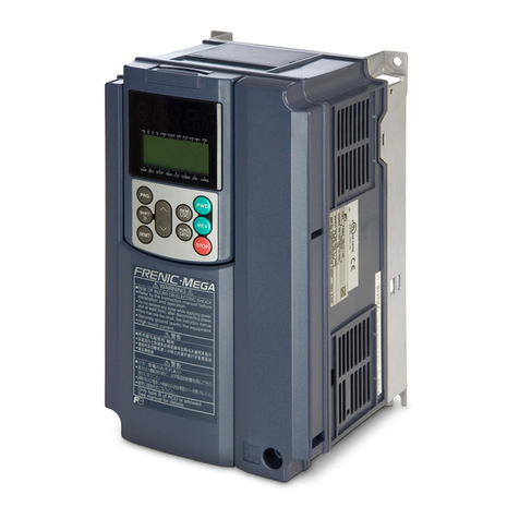
Fuji Electric Frenic Mega Series User manual

Fuji Electric

Fuji Electric Frenic Mega Series User manual

Fuji Electric Frenic-Sce User manual

Fuji Electric

Fuji Electric Frenic-Sce User manual

Fuji Electric FRENIC-MEGA User manual

Fuji Electric

Fuji Electric FRENIC-MEGA User manual

Fuji Electric FRN0025C2S-2U User manual

Fuji Electric

Fuji Electric FRN0025C2S-2U User manual

Fuji Electric FRENIC-Multi User manual

Fuji Electric

Fuji Electric FRENIC-Multi User manual

Fuji Electric frenic mini series User manual

Fuji Electric

Fuji Electric frenic mini series User manual

Fuji Electric FRENIC-Ace series User manual

Fuji Electric

Fuji Electric FRENIC-Ace series User manual

Fuji Electric MICREX-SX series User manual

Fuji Electric

Fuji Electric MICREX-SX series User manual

Fuji Electric Frenic Mega Series User manual

Fuji Electric

Fuji Electric Frenic Mega Series User manual

Fuji Electric FRENIC-Eco Series User manual

Fuji Electric

Fuji Electric FRENIC-Eco Series User manual

Fuji Electric frenic mini series User manual

Fuji Electric

Fuji Electric frenic mini series User manual

Fuji Electric FRENIC 5000G11S/P11S User manual

Fuji Electric

Fuji Electric FRENIC 5000G11S/P11S User manual

Fuji Electric Frenic-Mini User manual

Fuji Electric

Fuji Electric Frenic-Mini User manual
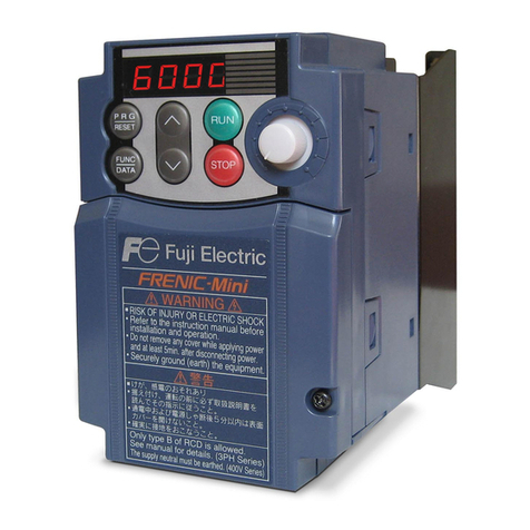
Fuji Electric Frenic Mini FRNF12C1S-2U User manual

Fuji Electric

Fuji Electric Frenic Mini FRNF12C1S-2U User manual

Fuji Electric FRENIC-Mini (C2) User manual

Fuji Electric

Fuji Electric FRENIC-Mini (C2) User manual

Fuji Electric frenic 5000g11s User manual

Fuji Electric

Fuji Electric frenic 5000g11s User manual

Fuji Electric FRENIC-Lift LM2A Series User manual
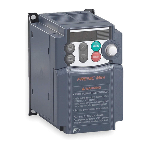
Fuji Electric

Fuji Electric FRENIC-Lift LM2A Series User manual

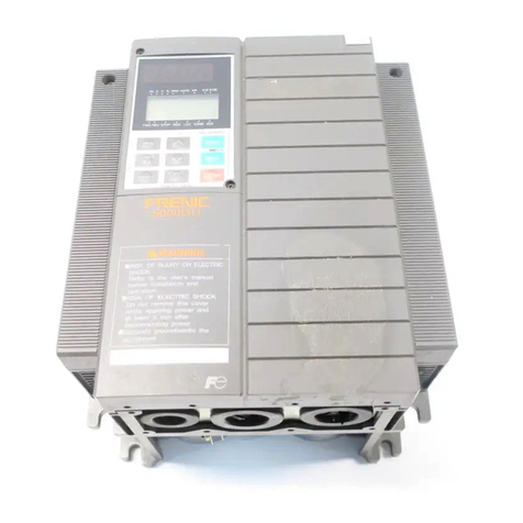
Fuji Electric FRENIC5000P11S Series User manual
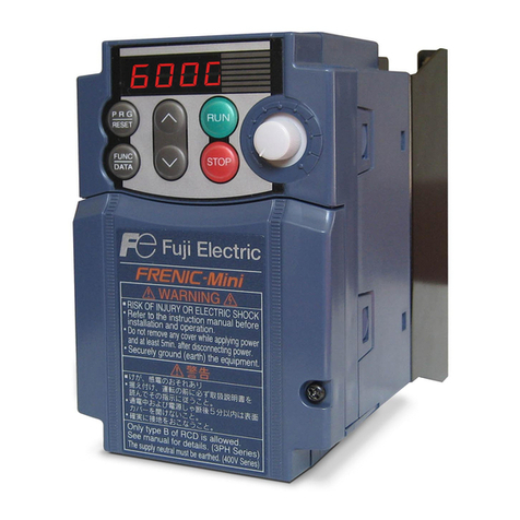
Fuji Electric

Fuji Electric FRENIC5000P11S Series User manual

Fuji Electric FRENIC-eHVAC User manual

Fuji Electric

Fuji Electric FRENIC-eHVAC User manual

Popular Inverter manuals by other brands

Hitachi WJ200 Series Software Quick reference guide

Hitachi

Hitachi WJ200 Series Software Quick reference guide

Deye SUN-12K-SG01LP1-EU user manual

Deye

Deye SUN-12K-SG01LP1-EU user manual

Fairland TurboSilence IXCR26V manual

Fairland

Fairland TurboSilence IXCR26V manual

SolarMax SM30HT4 instruction manual

SolarMax

SolarMax SM30HT4 instruction manual

Srne HF2420U60-100 user manual

Srne

Srne HF2420U60-100 user manual

FLOWTECH 103 Operation and maintenance manual

FLOWTECH

FLOWTECH 103 Operation and maintenance manual

Fimer UNO-DM-3.3-TL-PLUS-US-Q product manual

Fimer

Fimer UNO-DM-3.3-TL-PLUS-US-Q product manual

BONFIGLIOLI active operating instructions

BONFIGLIOLI

BONFIGLIOLI active operating instructions

Renac Pre R3 Series user manual

Renac

Renac Pre R3 Series user manual

Solar Xantrex 784-0110 installation guide

Solar

Solar Xantrex 784-0110 installation guide

Toshiba TOSVERT VF-S9 instruction manual

Toshiba

Toshiba TOSVERT VF-S9 instruction manual

Trace Engineering LEGEND I Owner's/operator's manual

Trace Engineering

Trace Engineering LEGEND I Owner's/operator's manual

Pragma TREKHY user manual

Pragma

Pragma TREKHY user manual

Growatt TL3-X Series Installation & operation manual

Growatt

Growatt TL3-X Series Installation & operation manual

Power One 10kW-SGTU-103 installation guide

Power One

Power One 10kW-SGTU-103 installation guide

Kensington 33214 user manual

Kensington

Kensington 33214 user manual

Growatt MAC 60KTL3-X LV Installation & operation manual

Growatt

Growatt MAC 60KTL3-X LV Installation & operation manual

INFOSEC C3 MPPT user guide

INFOSEC

INFOSEC C3 MPPT user guide

manuals.online logo
manuals.online logoBrands
  • About & Mission
  • Contact us
  • Privacy Policy
  • Terms and Conditions

Copyright 2025 Manuals.Online. All Rights Reserved.