Singmai Electronics SM06 User manual
SingMai Electronics
SM06
User Manual Revision 0.
4
Page
1
of
26
SM06
Advanced Composite Video Interface:
HD-SDI to aCVi
converter module
User Manual
Revision 0.4
1st May 2017

SingMai Electronics
SM06
User Manual Revision 0.
4
Page
2
of
26
Revision History
Date Revisions Version
17-07-2016 First Draft. 0.1
28-08-2016 Added support for NTSC/PAL encoding. 0.2
30-12-2016 Updates for Revision 2 PCB. 0.3
01-05-2017 DVI inputs removed.
NTSC/PAL inputs removed.
Minor schematic changes.
Auto standard detection of 29/59Hz
standards.
0.4

SingMai Electronics
SM06
User Manual Revision 0.
4
Page
3
of
26
Contents
Revision History....................................................................................................................................... 2
Contents................................................................................................................................................... 3
Tables ....................................................................................................................................................... 3
Figures...................................................................................................................................................... 3
1. Introduction ...................................................................................................................................4
2. aCVi Overview ................................................................................................................................ 5
3. Connecting up the module ............................................................................................................ 7
4. Automatic Cable length compensation. ..................................................................................... 10
5. Circuit description .........................................................................................................................12
6. Specification................................................................................................................................. 24
7. Power Supply Specification......................................................................................................... 25
Tables
Table 1 aCVi supported video formats....................................................................................................5
Figures
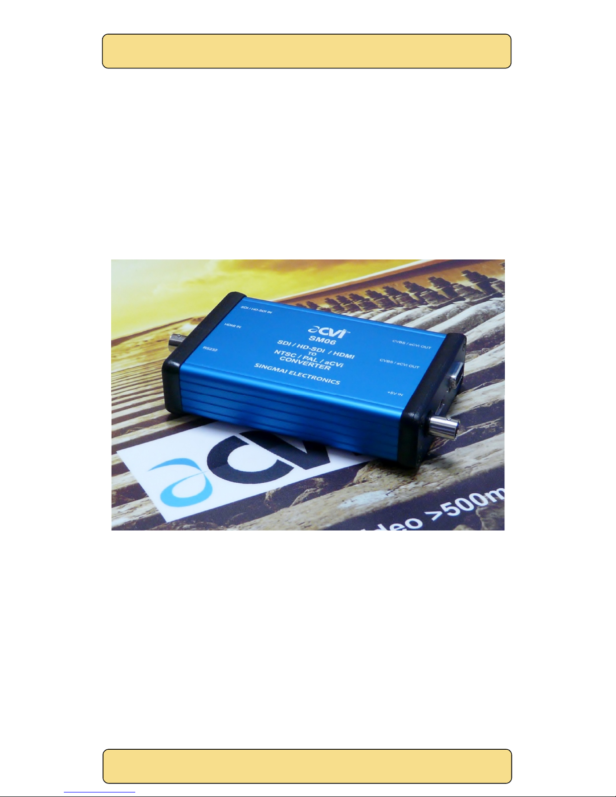
Figure 1 SM06 module.............................................................................................................................4
Figure 2 aCVi Spectrum. ..........................................................................................................................6
Figure 3 SM06 Interconnections. ........................................................................................................... 7
Figure 4 UTP connector pin assignments...............................................................................................8
Figure 5 SM06 Data slicing selection - J9. ..............................................................................................8
Figure 6 aCVi cable length compensation (lines 7,8 and 9 of the VBI). .............................................. 10
Figure 7 Original HD-SDI image (screen capture). ................................................................................ 11
Figure 8 aCVi image after transmission through 300m of RG59 cable (screen capture).................... 11
Figure 9 SM06 Schematics - Sheet 1. .................................................................................................... 14
Figure 10 SM06 Schematics - Sheet 2. ...................................................................................................15
Figure 11 SM06 Schematics - Sheet 3. ................................................................................................... 16
Figure 12 SM06 Schematics - Sheet 4. ...................................................................................................17
Figure 13 SM06 Schematics - Sheet 5. .................................................................................................. 18
Figure 14 SM06 Schematics - Sheet 6. .................................................................................................. 19
Figure 15 SM06 Schematics - Sheet 7. ..................................................................................................20
Figure 16 SM06 Schematics - Sheet 8. ...................................................................................................21
Figure 17 SM06 Schematics - Sheet 9. .................................................................................................. 22
Figure 18 SM06 Schematics - Sheet 10.................................................................................................. 23
Figure 19 Power supply specification, Page 1....................................................................................... 25
Figure 20 Power supply specification, Page 2......................................................................................26
SingMai Electronics
SM06
User Manual Revision 0.
4
Page
4
of
26
1. Introduction
SM06 is a transmitter module compatible with the aCVi Advanced Composite Video Interface
format. SM06 accepts HD-SDI input format which it converts to analogue aCVi encoded video for
driving both twisted pair and coaxial cable.
aCVi is a method to transmit HD video over long distances of existing coaxial or twisted-pair cable
networks or allow the use of less expensive RG-59/UTP cable in long distance installations.
SM06 supports the following HD standards: 720p-25/30/50/59.94/60Hz, 1080p-24/25/29.97/30Hz
and 1080i-50/59.94/60Hz. Switching between standards is automatic.
Figure 1 SM06 module.

SingMai Electronics
SM06
User Manual Revision 0.
4
Page
5
of
26
2. aCVi Overview
The following is a brief overview of the aCVi interface.
The basic concept of the aCVi interface is to build on the proven and reliable transport method of
NTSC. NTSC is capable of transmitting more than 1km across RG-59 cable but the bandwidth is
limited to 5MHz. Because the cable system is a closed system, it is only necessary for the
transmitter and receiver to ‘understand’ each other and we can modify the basic NTSC method to
suit HD transmissions.
According to the SMPTE-296M specification, HD (74.25MHz sampling) video transmission requires
a luma bandwidth of 30MHz and chroma bandwidth of 15MHz. To save on system costs aCVi
supports the 30MHz luma bandwidth but constrains the chroma bandwidth to 7.5MHz (4:1:1
sampling).
The colour difference signals are modulated onto a carrier in quadrature so they effectively use
the same bandwidth: the chroma subcarrier is ~24.75MHz.. The high frequency luma and the
modulated chroma overlap above 12.4MHz but because of the line to line phase relationship of the
chroma, may be separated using a line comb filter (and also because of the use of single chip
image sensors, there is usually little high frequency content to cause image artifacts).
The effective bandwidth of the complete signal is therefore approximately 12.3MHz (chroma
upper sideband + filter roll off) + 24.75MHz or about 37MHz, setting a minimum sampling
frequency of 2 x 37MHz or 74MHz. For convenience we choose 74.25MHz as a sampling frequency
as this is related to the SMPTE272M standard; (see Figure 2).
For transmission over 300m of RG-59 cable we can expect 18dB loss at higher frequencies
(6.2dB/100m @ 50MHz). However the synchronizing signals are at a much lower frequency where
the loss is only about 1-2dB so reliable rastering of the received signal should always be assured.
The peak to peak video level of aCVi is 1.8V (75% colour bars) which maintains compatibility with
any legacy SD equipment on the network and also allows common low-power 5V drivers to be
used. Table 1 lists the currently supported video formats for aCVi.
Format Pixels/line Line
frequency
FSC/FH
ratio
Subcarrier
720p/25Hz 3960 18.75kHz 1320.5 24.759375MHz
720p/30Hz 3300 22.5kHz 1100.5 24.76125MHz
720p/50Hz 1980 37.500kHz 660.5 24.76875MHz
720p/59.94Hz
1
1650 44.955kHz 550.5 24.74775226MHz
720p/60Hz 1650 45.000kHz 550.5 24.7725MHz
1080p/24Hz 2750 27.0kHz 916.5 24.7455MHz
1080p/25Hz 2640 28.125kHz 880.5 24.7640625MHz
1080p/29.97Hz
1
2200 33.716kHz 734.5 24.73089411MHz
1080p/30Hz 2200 33.750kHz 733.5 24.755625MHz
1080i/50Hz 2640 28.125kHz 880.5 24.7640625MHz
1080i/59.94Hz
1
2200 33.716kHz 734.5 24.73089411MHz
1080i/60Hz 2200 33.750kHz 733.5 24.755625MHz
Table 1 aCVi supported video formats.
1Input clock is 148.3516484MHz (else 148.5MHz).
Table of contents
Other Singmai Electronics Media Converter manuals


Popular Media Converter manuals by other brands


H&B
H&B TX-100 Installation and instruction manual

Bolin Technology
Bolin Technology D Series user manual

IFM Electronic
IFM Electronic Efector 400 RN30 Series Device manual

GRASS VALLEY
GRASS VALLEY KUDOSPRO ULC2000 user manual

Linear Technology
Linear Technology DC1523A Demo Manual

Lika
Lika ROTAPULS I28 Series quick start guide

Weidmuller
Weidmuller IE-MC-VL Series Hardware installation guide

Optical Systems Design
Optical Systems Design OSD2139 Series Operator's manual

Tema Telecomunicazioni
Tema Telecomunicazioni AD615/S product manual

KTI Networks
KTI Networks KGC-352 Series installation guide

Gira
Gira 0588 Series operating instructions

Lika
Lika SFA-5000-FD user guide