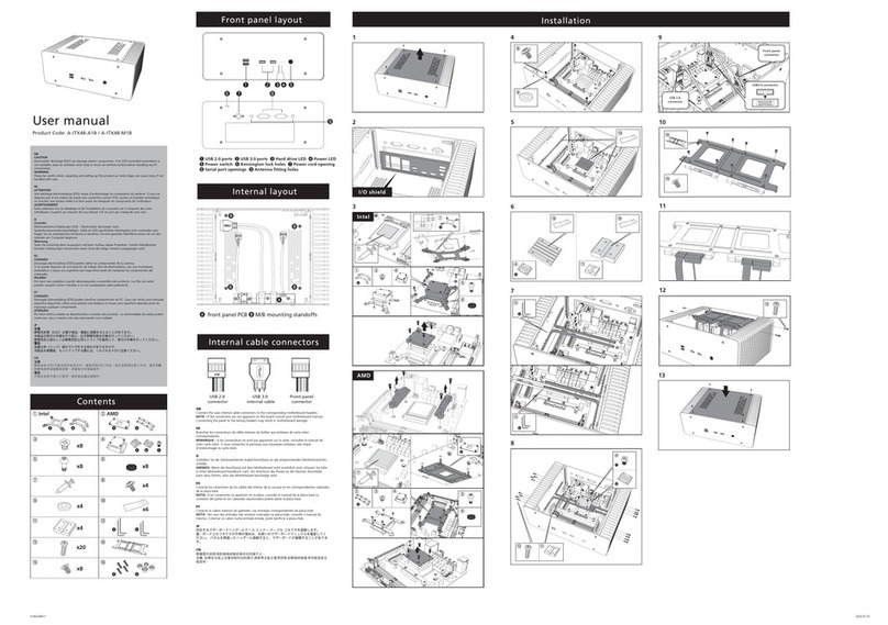
SINGULARITY COMPUTERS SPECTRE INTEGRA-M User manual

vv
Revision 1.1

Spectre Integra-M/MA Assembly Manual
Revision 1.1
Page | 1
Table of Contents
Introduction.......................................................................................................................................................... 2
Spectre Integra-M/MA Features................................................................................................................... 3
Spectre Integra-M/MA Specifications......................................................................................................... 5
Included Items..................................................................................................................................................... 6
Table of Fasteners & Panels........................................................................................................................... 7
Warranty ............................................................................................................................................................... 8
Assembly Manual............................................................................................................................................... 9
Step 1: Install ARGB 50cm LED Strips......................................................................................................... 9
Step 2: Install Power Button. ..................................................................................................................... 10
Step 3: Install Legs onto Distribution Plate. ........................................................................................... 11
Step 4: Install Feet and Top Supports. .................................................................................................... 12
Step 5: Install LED Diffusors & Radiator Panels....................................................................................13
Step 6: Assemble and attach PSU Shroud. ............................................................................................. 14
Step 7: Install PCIe 4.0 Vertical GPU Mount............................................................................................15
Step 8: Install PCIe 4.0 2nd Vertical GPU Mount. ................................................................................... 16
Step 9: Install I/O Panel................................................................................................................................17
Step 10: Install SSD Tray into PSU Shroud.............................................................................................. 18
Step 11: Install D5 Pump (Not included). ................................................................................................. 19
Step 12: Install Side Panel Window. .........................................................................................................20
Step 13: Filling & Draining The Loop. ....................................................................................................... 21
Installing Radiators ......................................................................................................................................... 21
Liquid Cooling System Layout ......................................................................................................................22
Spectre Integra-M/MA PowerBoard ..........................................................................................................23

Spectre Integra-M/MA Assembly Manual
Revision 1.1
Page | 2
Introduction
Spectre Integra-M Dark
Spectre Integra-M Dark has a space theme with aesthetics inspired by fighter jets and spacecraft.
It has a 3-layer distribution plate where Spectre Integra-M which has a 2-layer distribution plate
built from clear acrylic. Spectre Integra-M Dark has a clear acrylic cover and motherboard tray,
the main distribution plate layer is grey tinted acrylic, the rear distribution plate layer is clear
acrylic, and the rear cover is satin black acrylic. The reservoir volume is much larger allowing for
easier filling and bleeding, and increased flow.
Spectre Integra-M
Spectre Integra-M is a more compact ATX version of Spectre. It is a full re-design using everything
we have learned from the development of Spectre which has continued since 2015. Integra-M is
25% smaller than Spectre 3.0 (all versions) but maintains all the features, except that it fits ATX
motherboards and two 360mm radiators which are 40mm thick. Integra-M has a large part of the
water-cooling loop integrated with a completely new distribution plate design. It has a fully
integrated solution for cables with the Singularity Computers PowerBoard. Previously we have
created PowerBoards for existing cases, but for Integra-M we have developed the PowerBoard
and case together. This means that both have become far more streamlined, meaning more
features and compatibility. The PowerBoard supports the most high-end components and
includes two of the new 12VHPWR connectors along with x3 8pin PCIE connectors. It has built in
filter capacitors, 24 integrated ARGB and UV LEDs facing inwards and outwards, integrated direct
connect SATA, power, and reset buttons, and a touch activated power button. There is no rear
access needed to the case for cable management, all cables can be connected from the front and
little to no cable management is needed. Black sleeved linking cables are included with the case.
Custom colored sleeved linking cables can be purchased separately.
Spectre Integra-MA
Integra-MA does not include a distribution plate but includes a PowerBoard. It is capable of
housing a high-end liquid cooled system with two 360mm radiators, the top one up to 40mm thick
and the front one up to 60mm thick. The Singularity Computers PowerBoard is an integrated
solution for cables, lighting and much more. Previously we have created PowerBoards for existing
cases, but for Integra we have developed the PowerBoard and case together. This means that
both have become far more streamlined, meaning more features and compatibility. The
PowerBoard supports the most high-end components and includes two of the new 12VHPWR
connectors. The PowerBoard has built in filter capacitors, 24 integrated ARGB and UV LEDs facing
inwards and outwards, integrated direct connect SATA, power, and reset buttons, and a touch
activated power button. There is no rear access needed to the case for cable management, all
cables can be connected from the front and little to no cable management is needed. Black
sleeved linking cables are included with the case. Custom colored sleeved linking cables can be
purchased separately.

Spectre Integra-M/MA Assembly Manual
Revision 1.1
Page | 3
Spectre Integra-M/MA Features
•Integrated Liquid Cooling Features (Integra-M only)
Reservoir, D5 Pump Top, D5 Pump Cover, Fill Port, Drain Port, parts of the cooling loop.
•PowerBoard Integration
The PowerBoard is a PCB integrating 24pin, EPS, PCIE and 12VHPWR along with PWM and ARGB
Hubs, SATA and Power and Reset Buttons. The Spectre Integra-M PowerBoard also has an
integrated touch sensing Power Button. The PowerBoard has x24 ARGB and UV LEDs
positioned around the external and internal perimeter to optimally light up the distribution
plate. The LEDs can be switched on or off and you can switch between ARGB or UV or have both
on at the same time. Essentially the PowerBoard is a distribution plate for cables also
integrating other features and functions. It is a new method for cables allowing
standardization of cable lengths and making cable management almost unnecessary. Spectre
Integra-M comes included with a standard set of black sleeved linking cables including 24pin
x1, 8pin EPS x2, 8pin PCIE x3 meaning that these cables don’t have to be purchased separately.
•Reduced build time due to integration
With the core component cables, PWM and ARGB hubs all integrated there is less assembly to
be done, there is almost no cable management thanks to the PowerBoard integration. Even
further build time reduction on Integra-M with the pump, reservoir, fill & drain ports and parts
of the water-cooling loop are integrated.
•Integration Cost Component
A large portion of the case cost is due to the integration. These are components you do not
have to purchase for your build. The pump, reservoir, cables, hubs, less fittings, less tube, no
lighting, no cable combs, or cable management components. Integra-M reduces cost further
on water-cooling components.
•Integration & Optimization
With the integration we did not just develop a case, we also developed all the integrated
components. This meant that we could focus more on optimization than would normally be
possible. The integrated loop routes in Spectre Integra-M allow for more flow than 16mm
tubes. The pump top was designed for the D5 pump, maximizing flow to and from the
distribution plate. The reservoir was designed to remove air as quickly as possible making the
loop easier to fill. The fill port is at the highest point on the back for the case and the drain point
at the lowest point.

Spectre Integra-M/MA Assembly Manual
Revision 1.1
Page | 4
•High End Components
Spectre Integra-M/MA fits ATX motherboards and has 7 expansion slots. It is designed to fit
the largest high-end GPUs. It can fit the largest PSUs up to 220mm. For the water-cooling
system it can fit 2x 360mm radiators 45mm thick with a single set of fans and the D5 pump.
The PowerBoard can handle the most high-end PSUs and components.
•Radiator Adjustment
The radiator mounting panels have a large range of adjustment to help with port alignment to
the distribution plate.
•Storage
Spectre Integra-M/MA has 7x 2.5” Drive positions. Two are on the top of the PSU shroud, four
inside of the PSU shroud and there is one integrated on the PowerBoard. The two on top of the
PSU shroud cannot be used with vertically mounted GPUs.
Design & Engineering
We have been building high end water-cooled systems for over 15 years. Our approach to product
development begins with a need for our own builds and so the origin is always function. From
there we start to build ideas around this function and the aesthetics and everything else follows.
The original ideas for our products came from years of building highly customized, high end
water-cooled systems and trying to reduce the exceptionally long build times and complexity.
Our approach to development is hands on, we are using and testing our own products every day.
Manufacturing & Quality
Almost all components of Spectre Integra-MA are CNC machined from a solid block of material
with extreme precision. Everything is carefully assembled by hand and tested. Our approach and
philosophy are that there is no hidden or back side, everything is on display and so the design is
a celebration of the raw materials and the manufacturing processes with everything on display.

Spectre Integra-M/MA Assembly Manual
Revision 1.1
Page | 5
Spectre Integra-M/MA Specifications
Water-cooling Integration
(Integra-M only)
Reservoir, Pump Top, Pump Cover, Fill Port, Drain Port, Parts of water-cooling
loop.
Ports: x6 G1/4” BSPP. 1x Fill Port. 1x Drain Port.
Pump: (Not included): Compatible with all D5 pumps.
Electronics Integration Core Component Cables: 24pin x1. 8pin EPS x2. PCIE 8pin x3. 12VHPWR x2. 6pin
PCIE MB Supplementary x1.
Hubs: PWM: x3. ARGB: x10 (Single input for each).
LEDs: x24 Integrated ARGB 90-degree LEDs and x24 UV 90-degree LEDs facing
around the internal and external perimeter of the PowerBoard. There are two
switches on the PowerBoard one switches the ARGB on or off and the other
switches the UV on or off.
Touch sensing Power Button.
Extra Power and Reset Buttons.
PowerBoard LED on/off switch.
PowerBoard 2.5” SATA 3.0 6Gb/s Direct Mount x1.
Cables PowerBoard Linking Cables Standard Set: 24pin x1. 8pin EPS x2. 8pin PCIE x3.
18AWG Black Headshrinkless Sleeve.
PWM Female to Female 50cm Black Sleeved x1.
ARGB Female to Female 50cm Black Sleeved x1.
Touch Power Button and extra Power and Reset Button Cables 20cm x4.
LED strips
x2 50cm ARGB LED Strips with 50cm cables.
(Attach to case panels on specific mounting points for front and top panel
glow).
Motherboard Form Factor
ATX, Mini-DTX, Mini-ITX.
Expansion Slots x7.
Case Form Factor
Mid Tower.
Package Dimensions &
Weight
640 mm(L) x 620 mm(W) x 110 mm(H).
(Flat-packed Case | Partial assembly required).
Integra-M: 14kg. | Integra-MA: 12kg.
Case Dimensions & Weight 486 mm(L) x 245 mm(W) x 528 mm(H).
Integra-M: 12kg. | Integra-MA: 10kg.
Storage
7x 2.5” Drive
x2 are on top of the PSU shroud and cannot be used when the GPUs are
vertically mounted.
x4 are inside of the PSU Shroud.
x1 is on the PowerBoard behind the PSU.
Radiators Integra-M:360mm x 40mm with x1 set of standard 25mm fans.
Integra-MA: 360mm x 60mm front, 360mm x 40mm top, each with x1 set of
standard 25mm fans.
Maximum GPU Length 410mm with radiator installed.
Maximum GPU Height
170 mm in standard orientation | Unlimited in vertical orientation
Maximum CPU Cooler Height
170 mm
Maximum PSU Length 220mm (Space allowed for cables inside of PSU shroud).

Spectre Integra-M/MA Assembly Manual
Revision 1.1
Page | 6
Front Panel I/O No Front I/O | Vandal Switch 16mm | White LED
Vertical GPU Mount x2 with 3 slots (60mm) spacing. x1 is included. 2nd Vertical GPU Mount
Available Separately here.
Riser cable not included, compatible with Linkup PCIE 4.0 Riser Cables.
Materials 6061 Aluminum Anodized. Cast Acrylic | Stainless Steel | PCB
Manufacturing Process CNC Mill, CNC Lathe, CNC Router, PCB.
Assembly Distribution Plate Assembled by Hand. Acrylic backplate with PowerBoard
assembled by hand. Metal Components need to be assembled and attached to
the Acrylic backplate by the customer.
Testing/Validation
(Integra-M only)
All Distribution Plates are factory pressure tested and precise fastener tension
is applied.
Included Items
Items
Spectre
Integra-M Integra-MA
Case Components
Distribution Plate with PowerBoard
1
-
Acrylic backplate with PowerBoard - 1
Clear Cast Acrylic Side Panel Window 1 1
Case Panel Set 16 16
LED Diffusors 2 2
Top corner acrylic cover with logo. 1 1
Vertical GPU Mount (Includes Vertical GPU Bracket and
Angle Mount). 1 1
Cables
PowerBoard Linking Cables Standard Set:
•
24pin
•8pin EPS
•
8pin PCIe
1
2
3
1
2
3
PWM Female to Female 50cm Black Sleeved
1
1
ARGB Female to Female 50cm Black Sleeved
1
1
Touch Power Button and extra Power and Reset Button
Cables 20cm
4 4
Accessories
Hex Keys:
•M3
1
1
1
1
1
1
•
M4
•
M6
Microfiber Cloth 1 1
Stop Fittings 2 2

Spectre Integra-M/MA Assembly Manual
Revision 1.1
Page | 7
Table of Fasteners & Panels
Fasteners
Type
Quantity
Type
Quantity
M3 x 6mm 12 M4 x 20mm 6
M4 x 6mm 22 M6 x 20mm 12
M4 x 8mm 3 M4 x Springwasher 6
M4 x 10mm 6 Standoff M3-M4 18mm 9
M4 x 12mm 4 Standoff M4 M-F 13mm 4
M4 x 16mm 2
Panels
Name
Radiator Panels
PSU Side Shroud
PSU Top Shroud
PSU Bottom Shroud
Top Supports
PSU Front Shroud
PSU Mount
Front Cover
Top Cover
Legs
LED Diffusors
I/O Panel
Feet

Spectre Integra-M/MA Assembly Manual
Revision 1.1
Page | 8
Warranty
Spectre Integra-M/MA 2-Year Limited Warranty:
1: The Integrated Water-cooling system is pressure tested at the factory, there is no need to
adjust the fasteners on the distribution plate. Take care not to over tighten any of the fasteners
particularly on the acrylic, stop as soon as you feel feedback or tension on the fastener. On the
metal parts you can tighten normally. We are not responsible for damage caused by over-
tightening the fasteners.
2: Any thread stripping, cross threading or thread damage will not be covered under our warranty.
All threads are pre-tested. We use stainless steel fasteners which are extremely durable.
3: All acrylic is carefully checked for scratches, marks or particles as the manifold is assembled.
We are not responsible for mistreatment of the acrylic. Only clean with a microfiber cloth and use
nothing except distilled or deionized water for cleaning, or Novus Plastic Cleaner. Damage caused
by cleaning agents (particularly alcohols or solvents) is not covered under warranty.
4: Acrylic Surface Guarantee: Marks on acrylic which cannot be wiped away with a microfiber
cloth will only be covered under warranty under the following conditions: That they did not occur
after the item was shipped from the Singularity Computers Factory or Retailer. If there are more
than 5 marks which are beyond 5mm in length and visible when facing perpendicular to the
surface. Evidence of this must be photographed in detail and photographs must be taken
perpendicular to the surface. Marks must be easily visible in photographs.
5: For the latest coolant recommendations please visit http://bit.ly/sc-important-info. We are
not responsible for staining of the acrylic, but it has never been an issue with our products. Most
staining will be easy to remove by flushing out the loop with distilled water for 24hrs or using
Mayhems Blitz. If you are concerned about staining, then we suggest Mayhems Non-Stain Dyes.
6: Any damage which occurs after the item leaves the Singularity Computers Factory or our
Retailers is not covered under warranty. We are not responsible for shipping damage or
mishandling.

Spectre Integra-M/MA Assembly Manual
Revision 1.1
Page | 9
Assembly Manual
Assembly Note
Spectre is built from thick and strong CNC Machined aluminum components with tight tolerances.
There is no flex in the metal parts like there is on other cases. Due to this we have had to build
tolerances into all the mounting holes on Spectre Integra. If something does not align then loosen
all related fasteners on the surrounding panels to let the component settle in, then tighten the
fasteners again.
Step 1: Install ARGB 50cm LED Strips.
Remove the adhesive covers on the LED strips and stick them onto the positions marked in the
diagrams below. Make sure to put the cables in the correct orientation for the best cable
management, which depends where you plan on connecting them in your build. There should be
one LED strip installed onto the inside of LED Cover Front, another installed inside of LED Cover
Top and another installed on the inside of the top Radiator Panel.
IMPORTANT
: All three LED Strips need to be cut to length to fit into position. If you plan on using
the individually LED Strip functions then you need to know how many LEDs are remaining on
each LED Strip after you cut them. When you cut them, count how ma
ny LEDs are remaining on
each LED Strip and remember which header you will plug each one into. The
Spectre Integra M/
M
-A LED Strips each have 30 LEDs before they are cut.
Cut LED Strips on the sections marked in
the diagram below.

Spectre Integra-M/MA Assembly Manual
Revision 1.1
Page | 10
Step 2: Install Power Button.
Remove the Power Button retention ring and O-ring. Thread the cable through from the front of
the Front LED Cover until the Power Button is in position. Install the O-ring onto the Power Button
and then tighten the retention ring to hold it in position. The O-ring prevents the Power Button
from coming loose.

Spectre Integra-M/MA Assembly Manual
Revision 1.1
Page | 11
Step 3: Install Legs onto Distribution Plate.
Install the Legs onto the Distribution Plate using 8x M6x20mm fasteners. It is best to lay the legs
down on a table in position, then place the distribution plate on top, align the legs to the holes
and then install the fasteners.

Spectre Integra-M/MA Assembly Manual
Revision 1.1
Page | 12
Step 4: Install Feet and Top Supports.
Install the Feet, for each one using a M4 x 16mm fastener with an M4 Spring Washer on the middle
hole and 2x M4 x 10mm fasteners with M4 Spring Washers on the outer holes. It is best do this
with the distribution plate laying flat and on the edge of a table so that you can easily access the
Feet.
Install the Top Supports, for each one using 2x M4 x 20mm Fasteners per support. It is best to do
this with the case standing upright on the Fee.

Spectre Integra-M/MA Assembly Manual
Revision 1.1
Page | 13
Step 5: Install LED Diffusors & Radiator Panels.
Attach the Top Cover to one of the Radiator Panels with an LED Diffusor in between using 2x M4
x 10mm fasteners.
Attach the Front Cover to one of the
Radiator Panels with an LED Diffusor in
between and attach the assembly to
the front Leg of the case using 2x M4 x
20mm fasteners.

Spectre Integra-M/MA Assembly Manual
Revision 1.1
Page | 14
Step 6: Assemble and attach PSU Shroud.
Attach the PSU Bottom Shroud to the PSU
Mount and PSU Front Shroud using 4x M4 x
6mm fasteners.
Install the PSU Side Shroud using 2x M4 x
6mm fasteners at the top and 2x Standoff
M4 M-F 13mm at the bottom.
Install the PSU Top Shroud onto the PSU
Mount and PSU Front Shroud using 4x M4 x
6mm.

Spectre Integra-M/MA Assembly Manual
Revision 1.1
Page | 15
Step 7: Install PCIe 4.0 Vertical GPU Mount.
Step 1: Install Riser Cable.
Install the PCIe Riser Cable (not included). Check you
have the correct orientation (see diagram to the right).
The cutout side of the Vertical GPU Bracket PCIE 4.0
needs to line up with the protruding plastic cover under
the Vertical GPU Riser Cable. Install the Vertical GPU
Riser Cable onto the PCIE 4.0 Vertical GPU Bracket using
the 2x M3 x 10mm Fasteners, 2x M3 Nuts and 6 x M3
Washers (see the diagram to the right for fastener
orientation).
Step 2: Install PCIe 4.0 Vertical GPU Mount.
Remove the PSU Side Panel to gain access into the PSU Shroud. Install the Vertical GPU Bracket
PCIe 4.0 to the PSU Top Panel using the 2x M4 x 10mm Fasteners. The fasteners are installed from
underneath the PSU Top panel. There are several holes in the PSU Top Panel also for the 2nd
Vertical GPU Mount PCIe 4.0 and SSD Mounting so be careful to select the correct mounting holes.
Install the Vertical GPU Angle using the x2 6-32 x 0.25” Fasteners. Be careful to select the correct
position on the Rear IO Panel so that the angle is at the correct height for your GPU.
Note: You may need to adjust the position of the Riser Cable on the PCIE 4.0 Vertical GPU bracket
for correct GPU alignment.

Spectre Integra-M/MA Assembly Manual
Revision 1.1
Page | 16
Step 8: Install PCIe 4.0 2nd Vertical GPU Mount.
(This add-on needs to be purchased separately; it is not included with the case).
Step 1: Install Riser Cable.
Install the PCIe Riser Cable (not included). Check you
have the correct orientation (see diagram to the right).
The cutout side of the Vertical GPU Bracket PCIE 4.0
needs to line up with the protruding plastic cover under
the Vertical GPU Riser Cable. Install the Vertical GPU
Riser Cable onto the PCIE 4.0 Vertical GPU Bracket using
the 2x M3 x 10mm Fasteners, 2x M3 Nuts and 6 x M3
Washers (see the diagram to the right for fastener
orientation).
Step 2: Install 2nd PCIe 4.0 Vertical GPU Mount.
Remove the PSU Side Panel to gain access into the PSU Shroud. Install the PCIe 4.0 2nd Vertical
GPU Bracket to the PSU Top Panel using the 2x M4 x 10mm Fasteners. The fasteners are installed
from underneath the PSU Top panel. There are several holes in the PSU Top Panel also for SSD
Mounting so be careful to select the correct mounting holes.Remove the Vertical GPU Angle if it
is already installed. When installing the 1st and 2nd Vertical GPU Mounts both angle pieces are
installed with the same fasteners at the same time. These fasteners are included with the 2nd
Vertical GPU Mount and are not included with the case. Use the 2x 6-32 x 0.5” Fasteners to mount
the Vertical GPU Angle and the Vertical GPU 2nd Angle. These are both attached to opposite sides
of the Rear IO Panel facing opposite directions. Tighten the 2x 6-32 x 0.5" fasteners and then use
the 2x 6-32 Nuts to fix the Vertical GPU Second Angle in position. Be careful to select the correct
position on the Rear IO Panel so that the height is correct for your GPU.

Spectre Integra-M/MA Assembly Manual
Revision 1.1
Page | 17
Step 9: Install I/O Panel.
Install 2x M4 x 18mm Stand Offs onto the Top Support and then install the Rear IO Panel using 3x
M4 x 8mm fasteners.
a

Spectre Integra-M/MA Assembly Manual
Revision 1.1
Page | 18
Step 10: Install SSD Tray into PSU Shroud.
4x 2.5" drives can be installed into Spectre Integra-M/MA. There are two locations to install 2.5"
drives, the PSU Bottom Shroud or the PSU Top Panel. The PSU Bottom Shroud has 4x 2.5" side
mounted drive positions and it fits inside of the PSU shroud. The PSU Top Panel has 2x 2.5" drive
mounting positions which are blocked when the Vertical GPU Mount/s are used. The Spectre
Integra-M/MA integrated SATA Data cable management can fit a maximum of 4x SATA Data
cables.
See the diagrams below for the 2.5" drive mounting locations:
Note
PSU Top Shroud SSD mounting
locations cannot be used with
Vertical GPU mounts.

Spectre Integra-M/MA Assembly Manual
Revision 1.1
Page | 19
Step 11: Install D5 Pump (Not included).
Spectre Integra-M only.
It is easier to do this when the Case or Distribution Plate is horizontal because then you can
sustain downward pressure on the pump while tightening the pump cover to prevent the O-ring
moving out of position.
Position the O-ring in the D5 Pump Top O-ring Groove, make sure that it is not twisted, kinked, or
damaged. Push the pump into the pump top and twist side to side until you feel the O-ring has
settled into the O-ring groove. Then tighten the pump cover firmly onto the pump. Position the
pump cables where you need to for the best cable routing.
This manual suits for next models
1
Table of contents
Other SINGULARITY COMPUTERS Enclosure manuals
SINGULARITY COMPUTERS
SINGULARITY COMPUTERS WRAITH 2.0 User manual
SINGULARITY COMPUTERS
SINGULARITY COMPUTERS STREAM-S ITX User manual
SINGULARITY COMPUTERS
SINGULARITY COMPUTERS SPECTRE 2.0 User manual
SINGULARITY COMPUTERS
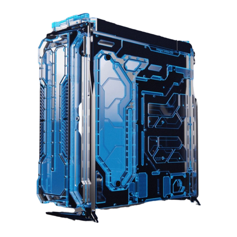
SINGULARITY COMPUTERS Spectre 3.0 Integra User manual
SINGULARITY COMPUTERS
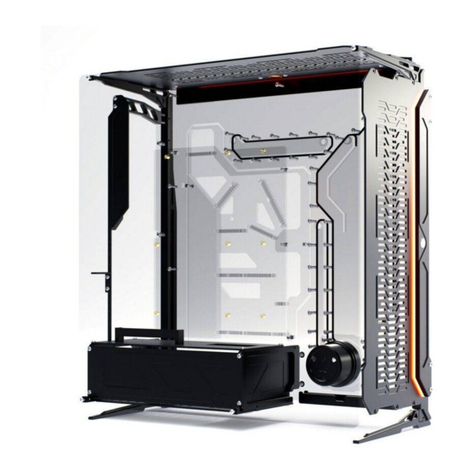
SINGULARITY COMPUTERS Eclipse Series User manual
SINGULARITY COMPUTERS
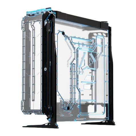
SINGULARITY COMPUTERS SPECTRE III User manual
SINGULARITY COMPUTERS
SINGULARITY COMPUTERS Spectre III Elite User manual
