GB.TBLZ66.110620
Swegon reserves the right to alter specifications.
2 www.swegon.com
7. Description of functions
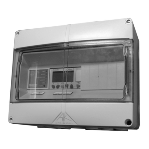
The ordinary control circuit card in the GOLD air handling
units controls its respective functions, but obtains set
points for certain functions of the control circuit card in
the control box.
The type of temperature and fan regulation to be used are
selected in the control panel of the control box.
All the other functions are set in the hand-held micro
terminal on the GOLD air handling unit that is the opera-
tional Master. The settings in the Master AHU are auto-
matically copied over to the Slave AHU.
5. Electrical connections
The electrical connections are to be wired by a qualified
electrician in accordance with local electrical safety regula-
tions.
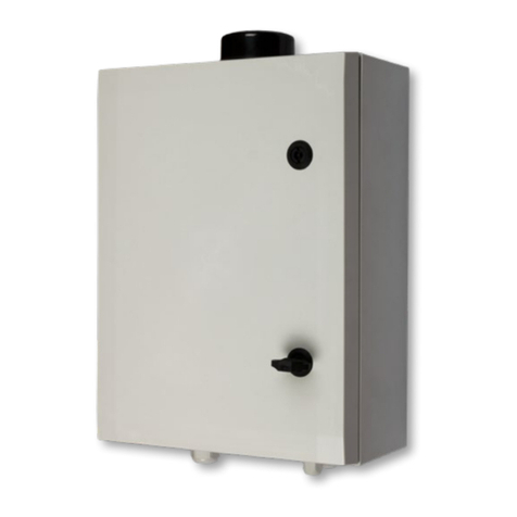
The supply voltage to the control box must be single-
phase, 230 V, and the cable conductors must be con-
nected to wiring terminals 101 (L) and 102 (N).
The control box must be connected to the control circuit
card of the GOLD air handling unit with twisted-pair,
shielded communication cables. Communication is con-
ducted via Modbus RTU and the control circuit card of the
control box is the communication Master.
The following wiring terminals must be connected as
specified below:
Terminal in the control box Terminal in GOLD unit
401 28 in the Master AHU
402 27 in the Master AHU
403 28 in the Slave AHU
404 27 in the Slave AHU
6. Commissioning
Energize the control box and both GOLD air handling
units.
Set the Modbus addresses for communication in both
GOLD units.
In the hand-held micro terminal, go to communication
below the Settings level.
Select EIA-485 and check under Protocol that Modbus
RTU is selected.
Go to Settings and set the following parameters:
Address 1 for the Master AHU and Address 2 for the Slave
AHU.
The speed should be 38,400; the parity should be “Even”;
Stop bits should be 1. This applies to both GOLD air han-
dling units
7.1 Temperature regulation:
ERS and Supply air regulation
ERS and supply air regulation are controlled in each GOLD
unit. The settings in the control box are automatically
transmitted over to the air handling units.
Extract air regulation.
The extract air controller is located inside the control
box. The extract air controller transmits set points to the
supply air controllers of the GOLD air handling units. The
air handling units are then automatically set for supply air
regulation.
The extract air controller in the control box receives values
for extract air temperature from the Master AHU’s extract
air temperature sensor or via communication from exter-
nal extract air /room sensors connected to the Master
AHU.
7.2 Fan regulation
Flow regulation
The total flow set on the control box panel is split equally
and is transmitted to the flow controllers of the GOLD air
handling units. The air handling units are then automati-
cally set for flow regulation.
Pressure regulation
The pressure regulation controller is located inside the
control box. The pressure controller controls how the air
handling units operate by transmitting flow set points to
both GOLD air handling units. The control circuit cards of
the air handling units maintain constant airflow in both air
handling units. The air handling units are then automati-
cally set for flow regulation.
The standard pressure sensor of the GOLD units are used
as duct pressure sensors in the common ducts. The duct
pressure sensors are connected to the Master AHU’s con-
nections marked Internal EIA-485.
The control box controller receives pressure values from
the Master AHU via the communication system.
Demand regulation
If demand regulation is used, the Master AHU’s extract
air fan is controlled via signals on wiring terminals, inputs
32-33. The supply air fan of the Master AHU is control-
led in response to the extract airflow as a Slave. The Slave
AHU copies the current flow regulation values and set
points from the Master air handling unit. The air handling
units are then automatically set for their respective func-
tions.
