Sintrones ABOX-5000PG1 User manual
ABOX-5000(P)G1
Embedded Computing
User's Manual
Version 1.0
Document Name ABOX-5000(P)G1 User Manual Document No. UM2018500020
Version 1.0 Date Jan. 31, 2018
Reversion History :
Reversion Date Notes Author(s)
From To
1.0 Jan. 31, 2018 Initial document issued Stanley Chou

User’s Manual Page i
SINTRONES®TechnologyCorp.
UserManual
Copyright
©2009bySINTRONES®TechnologyCorp.AllRightsReserved.
Nopartofthispublicationmaybereproduced,transcribed,storedinaretrievalsystem,
translatedintoanylanguage,ortransmittedinanyformorbyanymeanssuchas
electronic,mechanical,magnetic,optical,chemical,photocopy,manual,orotherwise,
withoutpriorwrittenpermissionfromSINTRONES®TechnologyCorp.
Otherbrandsandproductnamesusedhereinareforidentificationpurposesonlyand
maybetrademarksoftheirrespectiveowners.
Disclaimer
SINTRONES®TechnologyCorp.shallnotbeliableforanyincidentalorconsequential
damagesresultingfromtheperformanceoruseofthisproduct.
SINTRONES®TechnologyCorp.makesnorepresentationorwarrantyregardingthe
contentofthismanual.Informationinthismanualhadbeencarefullycheckedfor
accuracy;however,noguaranteeisgivenastothecorrectnessofthecontents.For
continuingproductimprovement,SINTRONES®TechnologyCorp.reservestherightto
revisethemanualormakechangestothespecificationsofthisproductatanytime
withoutnoticeandobligationtoanypersonorentityregardingsuchchange.The
informationcontainedinthismanualisprovidedforgeneralusebycustomers.
ThisdevicecompliestoPart15oftheFCCRules.Operationissubjecttothefollowingtwo
conditions:
1. Thisdevicemaynotcauseharmfulinterference.
2. Thisdevicemustwithstandanybackgroundinterferenceincludingthosethatmay
causeundesiredoperation.

User’s Manual Page ii
SafetyInformation
ReadthefollowingprecautionsbeforesettingupaSINTRONESProduct.
Electricalsafety
Topreventelectricalshockhazard,disconnectthepowercablefromtheelectrical
outletbeforerelocatingthesystem.
Whenaddingorremovingdevicestoorfromthesystem,ensurethatthepower
cablesforthedevicesareunpluggedbeforethesignalcablesareconnected.If
possible,disconnectallpowercablesfromtheexistingsystembeforeyouadda
device.
Beforeconnectingorremovingsignalcablesfromthemotherboard,ensurethatall
powercablesareunplugged.
Seekprofessionalassistancebeforeusinganadapterorextensioncord.These
devicescouldinterruptthegroundingcircuit.
Makesurethatyourpowersupplyissettothecorrectvoltageinyourarea.Ifyou
arenotsureaboutthevoltageoftheelectricaloutletyouareusing,contactyour
localpowercompany.
Ifthepowersupplyisbroken,donottrytofixitbyyourself.Contactaqualified
servicetechnicianoryourretailer.
Operationsafety
Beforeinstallingthemotherboardandaddingdevicesonit,carefullyreadallthe
manualsthatcamewiththepackage.
Beforeusingtheproduct,makesureallcablesarecorrectlyconnectedandthe
powercablesarenotdamaged.Ifyoudetectanydamage,contactyourdealer
immediately.
Toavoidshortcircuits,keeppaperclips,screws,andstaplesawayfromconnectors,
slots,socketsandcircuitry.
Avoiddust,humidity,andtemperatureextremes.Donotplacetheproductinany
areawhereitmaybecomewet.
Placetheproductonastablesurface.
Ifyouencountertechnicalproblemswiththeproduct,contactaqualifiedservice
technicianoryourretailer.

User’s Manual Page iii
CAUTION
Incorrectlyreplacingthebatterymaydamagethiscomputer.Replaceonlywiththesame
oritsequivalentasrecommendedbySINTRONES®TechnologyCorp.Disposeusedbattery
accordingtothemanufacturer'sinstructions.
TechnicalSupport
Pleasedonothesitatetocallore‐mailourcustomerservicewhenyoustillcannotfix
theproblems.
Tel:+886‐2‐82280101
Fax:+886‐2‐82280100
E‐mail:sales@sintrones.com
Website:www.sintrones.com

1.0 Introduction
User’s Manual
TABLEOFCONTENTS
Page #
1.0Introduction ............................................................................................................................... 1-1
1.1ModelSpecification.............................................................................................................. 1-1
1.2ABOX‐5000(P)G1Illustration(MB,System)................................................................... 1-3
1.3Architecture............................................................................................................................ 1-6
1.4PowerConsumption ............................................................................................................ 1-6
2.0InternalConnectorSpecification ............................................................................................ 2-1
2.1BatteryConnector(BAT1).................................................................................................. 2-1
2.2COMPortConnector(COM1/2) ......................................................................................... 2-2
2.3COMPortConnector(COM3/4) ......................................................................................... 2-3
2.4DI/DOConnector(DIO1) .................................................................................................... 2-4
2.5MCUDownConnector(MCU_CN1)..................................................................................... 2-5
2.6POWERButtonSwitch(SW1)............................................................................................. 2-6
2.7SATAPowerConnector(SPWR1&2) ................................................................................ 2-7
2.8SATAConnector(SATA1&2) ............................................................................................. 2-8
2.9SATADOMConnector(SATADOM1)................................................................................. 2-9
2.10MiniPCI‐EConnector(MINICARD1) ............................................................................... 2-11
2.11MiniPCI‐EConnector(MINICARD2) ............................................................................... 2-13
2.12MiniPCI‐EConnector(MINICARD3) ............................................................................... 2-15
2.13MiniPCI‐EConnector(MINICARD4) ............................................................................... 2-17
2.14M.2EKEYConnector(IDE1)............................................................................................. 2-19
2.15PSEPowerBoardConnector(PSE1)............................................................................... 2-21
3.0ExternalConnectorSpecification............................................................................................ 3-1
3.1PowerInputConnector(POWER1)................................................................................... 3-1
3.2HDMIPortConnector(HDMI1/2/3/4/5/6/7) .............................................................. 3-2
3.3AUDIOConnector(AUDIO1)............................................................................................... 3-4
3.4RJ45+USB3.0Connector(USB1&2).................................................................................. 3-5
3.5LANConnector(LAN3/4&LAN5/6) ................................................................................. 3-6
4.0SystemInstallation ................................................................................................................... 4-1
4.1SystemIntroduction ............................................................................................................ 4-1
4.2OpeningChassis.................................................................................................................... 4-1

1.0 Introduction
User’s Manual
4.3InstallingMemory ................................................................................................................ 4-3
4.4InstallingMINIPCIeExpansionCard(Minicard1,3G/LTE) ........................................ 4-5
4.5InstallingMINIPCIeExpansionCard(MiniCard2)........................................................ 4-7
4.6InstallingMINIPCIeExpansionCard(MiniCard3)........................................................ 4-9
4.7InstallingmSATAModule ................................................................................................. 4-12
4.8InstallingInternalAntennaCable................................................................................... 4-14
4.9InstallingSIMCard............................................................................................................. 4-18
4.10InstallingBatteryModule ................................................................................................. 4-20
4.11InstallingHDD..................................................................................................................... 4-22
4.12InstallingPOEModule ....................................................................................................... 4-25
4.13InstallingM.2Module ........................................................................................................ 4-28
5.0BIOS ............................................................................................................................................. 5-1
5.1EnterTheBIOS...................................................................................................................... 5-1
5.2Main ........................................................................................................................................ 5-3
5.3Advanced................................................................................................................................ 5-4
5.4Chipset.................................................................................................................................... 5-7
5.5Boot ......................................................................................................................................... 5-9
6.0PackingList ................................................................................................................................ 6-1
6.1PackingList ........................................................................................................................... 6-1

1.0 Introduction
User’s Manual
1.0
INTRODUCTION

2.0 Internal Connector Specification
User’s Manual
1.0 INTRODUCTION
1.1ModelSpecification
System
CPU
IntelGen7Core i7‐7700T (8MCache,upto3.80GHz)
IntelXeonQuadCoreE3‐1268Lv5(8MCache2.4GHzupto3.4GHz)
IntelGen6Corei7‐6700TE(8MCache2.4GHzupto3.4GHz)
IntelGen6Corei5‐6500TE(6MCache2.3GHzupto3.3GHz)
IntelGen6Corei3‐6100TE(4MCache2.7GHz)
IntelPentiumProcessorG4400TE(3MCache,2.40GHz)
Memory2xDDR42133MHzSO‐DIMMupto32GB
ChipsetIntel®Q170/C236PlatformControllerHub
LANChipset5xInteli210‐ATand1xi219LM(SupportiAMT)Gb/s
EthernetControllersOnboardSupportPXEandWOL
Audio1xLine‐out,1xMic‐inandLine‐in
Watchdog1~255LevelReset
TPM2.0
PowerRequirement
PowerInput9V‐48VDCPowerinput
PowerProtectionAutomaticsRecoveryShortCircuitProtection
PowerManagementVehiclePowerIgnitionforVarietyVehicle
PowerOffControlPoweroffDelayTimeSettingbyBIOSandSoftware
2.0 Internal Connector Specification
User’s Manual
BatteryInternalBatteryKitfor10MinsOperating(Optional)
Storage
Type2x2.5"DriveBayforSATATypeHDD/SSD,RAID0,1,5
1xmSATA
Qualification
CertificationsCE,FCCClassA,E13
Graphics
Graphics
NVIDIA®GeForceGTX1050GPU(768CUDACores)
SupportforOpenGL4.5andOpenCL™1.2
SupportforDirectX®12(FeatureLevel12_0)features
ResolutionMaxResolution(HDMI2.0b):7680x3840@60Hz
I/O
SerialPort4xRS‐232/422/485(AutoDirectionControl)
USBPort4xUSB3.0Ports
LAN6xRJ45PortsforGbE(Optionalfor4xPOE15.4Wperport)
VideoPort7xHDMIPorts
DIOPort8xGPIand4xGPO
Audio1xLine‐out,1xLine‐inand1xMic‐in
ExpansionBus3xFullMini‐PCIeSlotsand1xM.2A‐EKey2230Slot(2xSIMCard
Sockets)forLTE/3G,Wifi,Bluetooth,GPSfunction
Environment
OperatingTemp.‐40ºC~70ºC
StorageTemp.‐40ºC~80ºC
RelativeHumidity0%RH–95%RH
Vibration(random)IEC60068‐2‐64,random,2.5G@5~500Hz,1hr/axiswithSSD
VibrationOperatingMIL‐STD‐810G,Method514.6,ProcedureI,Category4
ShockOperating:MIL‐STD‐810G,Method516.6,ProcedureI,Trucksand
semi‐trailers=15G(11ms)withSSD
Mechanical
ConstructionAluminumAlloy
MountingWall‐mount,VESA‐mount,DinRailMountingKit
Weight3860g(Barebone)
Dimensions240(L)x226(W)x79(H)mm
2.0 Internal Connector Specification
User’s Manual
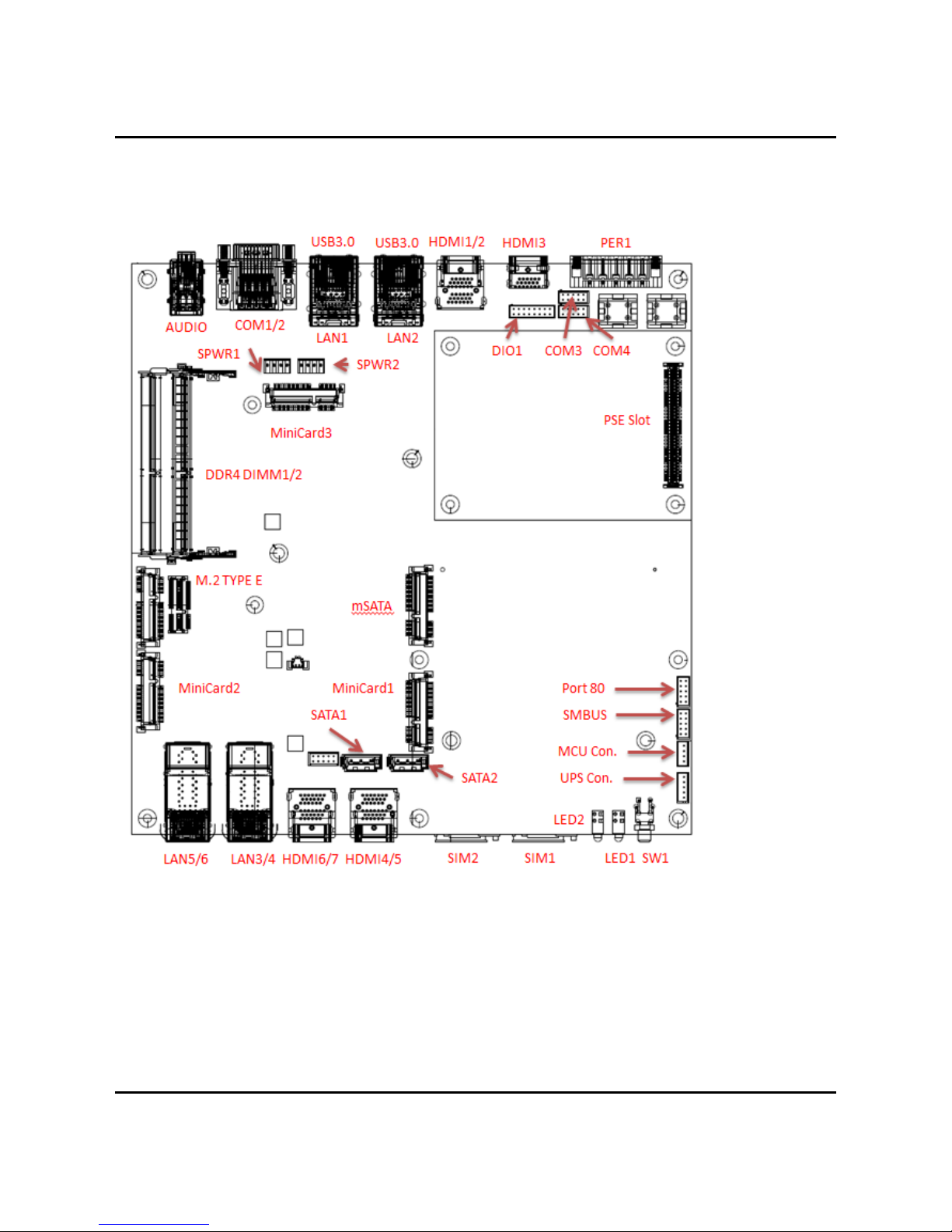
1.2 ABOX‐5000(P)G1Illustration(MB,System)
MainBoard

2.0 Internal Connector Specification
User’s Manual
FrontI/O
RearI/O

2.0 Internal Connector Specification
User’s Manual
System
2.0 Internal Connector Specification
User’s Manual
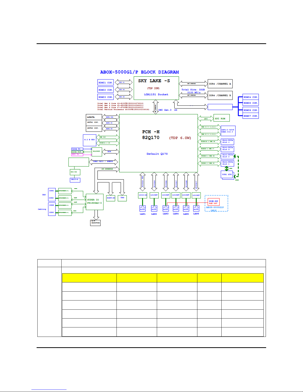
1.3 Architecture
1.4 PowerConsumption
Chip Description
Intel Power consumption:
CPU Core Frequency Cache TDP Tj
I7-7700T (4C/8T) 3.8 GHz 8M 35W 80°C
E3-1268L v5 (4C/8T) 3.4 GHz 8M 35W 100°C
i7-6700TE(4C/8T) 3.4 GHz 8M 35W 100°C
i5-6500TE(4C/4T) 3.3 GHz 6M 35W 100°C
i3-6100TE(2C/4T) 2.7 GHz 4M 35W 100°C
G4400TE(2C/2T) 2.4 GHz 3M 35W 100°C
GTX‐1050

2.0 Internal Connector Specification
User’s Manual
2.0
INTERNALCONNECTOR
SPECIFICATION
2.0 Internal Connector Specification
User’s Manual Page 2-1
2.0 INTERNALCONNECTORSPECIFICATION
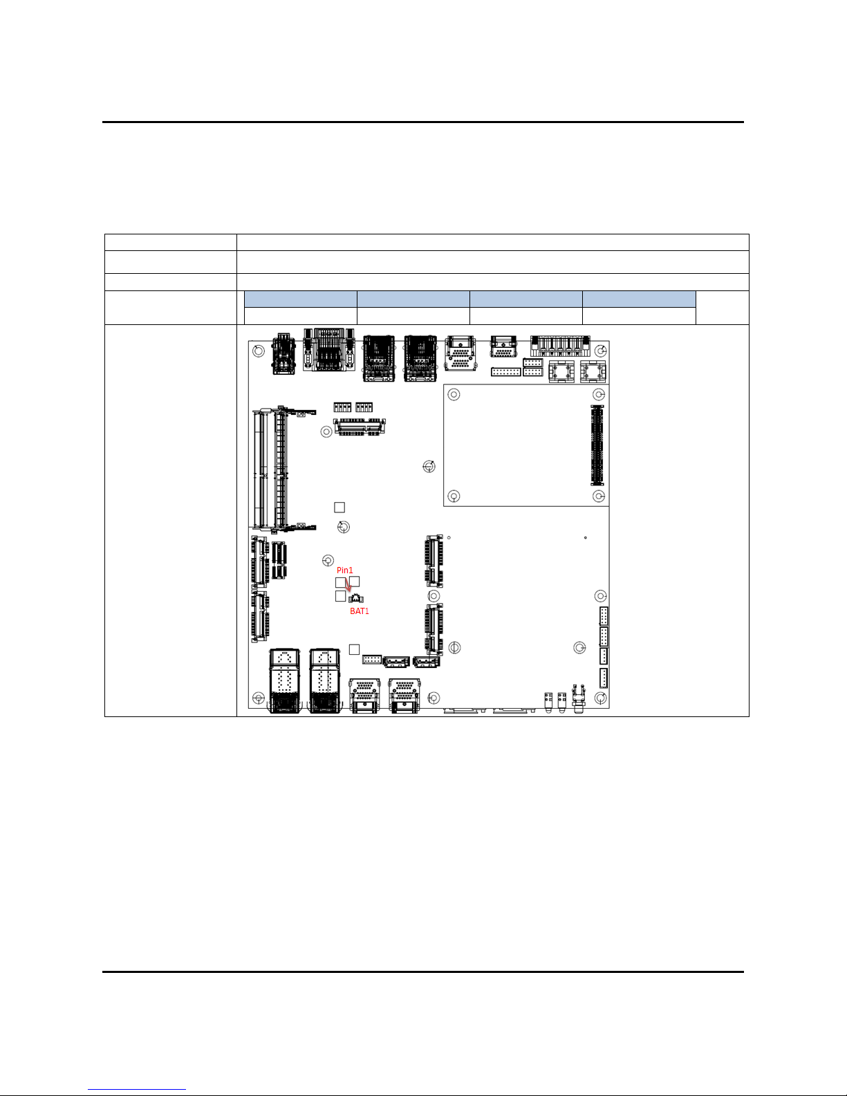
2.1BatteryConnector(BAT1)
Connector size 1 X 2 = 2 Pin
Connector type JST-1.25mm-M-180
Connector location BAT1
Connector pin
definition Pin Signal Pin Signal
1 +3VDC 2 GND
Connector map
2.0 Internal Connector Specification
User’s Manual Page 2-2
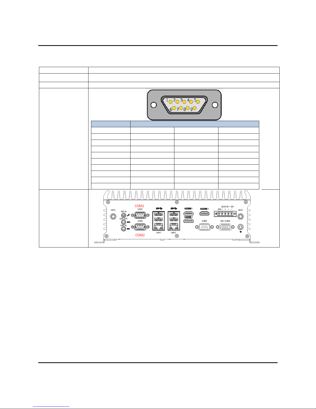
2.2COMPortConnector(COM1/2)
Connector size 2 X 5 = 10 Pin
Connector type Dual DB9 Connector
Connector location COM1/COM2
DB9 pin definition
Pin Signal
RS232 RS422 RS485
1 DCD TXD- TXD-/RXD-
2 RXD TXD+ TXD+/RXD+
3 TXD RXD+ NC
4 DTR# RXD- NC
5 GND GND GND
6 DSR# N/C N/C
7 RTS# N/C N/C
8 CTS# N/C N/C
9 RI# N/C N/C
Connector map
2.0 Internal Connector Specification
User’s Manual Page 2-3
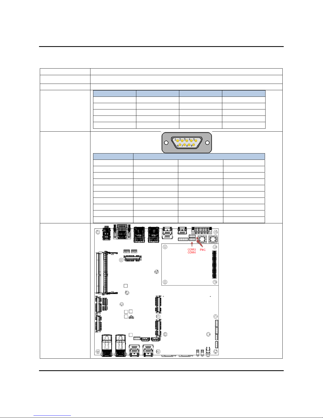
2.3COMPortConnector(COM3/4)
Connector size 2 X 5 = 10 Pin
Connector type JST-2.0mm-M-180
Connector location COM3/4
Connector pin
definition Pin Signal Pin Signal
1 DCD 2 RXD
3 TXD 4 DT
R
5 GND 6 DSR#
7 RTS# 8 CTS#
9 RI# 10 GND
DB9 pin definition
Pin Signal
RS232 RS422 RS485
1 COM2_DCD TXD- TXD-/RXD-
2 COM2_RXD TXD+ TXD+/RXD+
3 COM2_TXD RXD+ NC
4 COM2_DT
R
RXD- NC
5 GND GND GND
6 DSR# N/C N/C
7 RTS# N/C N/C
8 CTS# N/C N/C
9 RI# N/C N/C
Connector map
2.0 Internal Connector Specification
User’s Manual Page 2-4
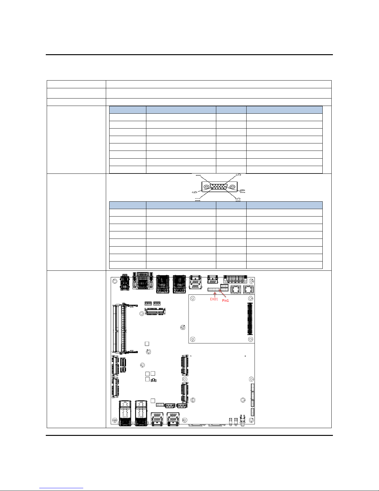
2.4DI/DOConnector(DIO1)
Connector size 2 X 8 = 16 Pin
Connector type JST-2.0mm-M-180
Connector location DIO1
Connector pin
definition Pin Signal Pin Signal
1 DO_1 2 DO_2
3 DO_3 4 DO_4
5 GND 6 GND
7 DI_1 8 DI_2
9 DI_3 10 DI_4
11 DI_5 12 DI_6
13 DI_7 14 DI_8
15 GND 16 CASE_GND
DB15MALE pin
definition
Pin Signal Pin Signal
1 DO_1 2 DO_2
3 DO_3 4 DO_4
5 GND 6 GND
7 DI_1 8 DI_2
9 DI_3 10 DI_4
11 DI_5 12 DI_6
13 DI_7 14 DI_8
15 GND
Connector map
2.0 Internal Connector Specification
User’s Manual Page 2-5
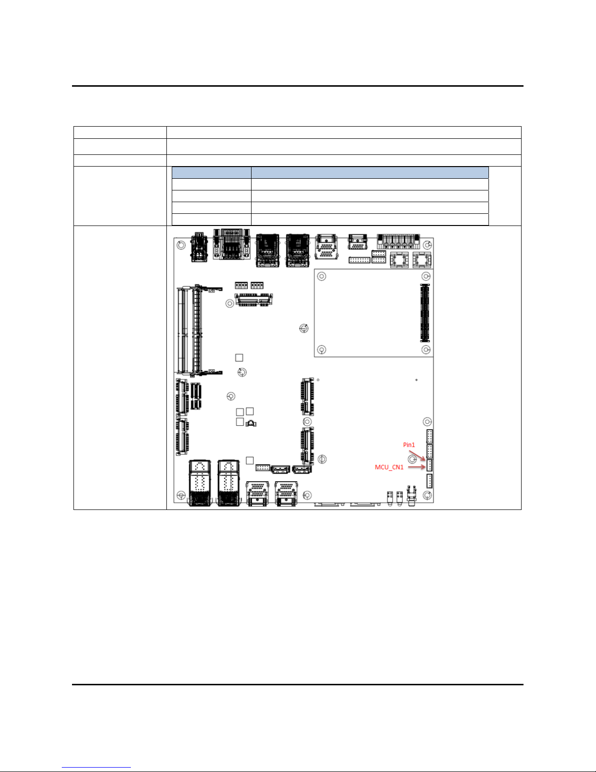
2.5MCUDownConnector(MCU_CN1)
Connector size 1 X 4 = 4 Pin
Connector type JST-2.0mm-M-180
Connector location MCU_CN1
Connector pin
definition Pin Signal
1 MCU_PROGRAM
2 RXD
3 GND
4 TXD
Connector map
2.0 Internal Connector Specification
User’s Manual Page 2-6
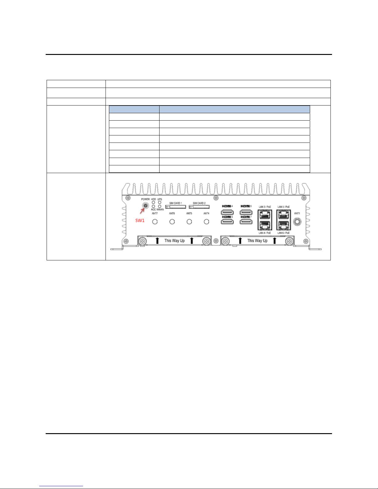
2.6POWERButtonSwitch(SW1)
Connector size 8 PIN
Connector type DIP-Switch
Connector location SW1
Connector pin
definition Pin Signal
1 GND
2 PWRBTN#
3 PWRBTN#
4 GND
C1 PWRLED_P (RED LED)
A1 PWRLED_N (GREEN LED)
MH1 N/C
MH2 N/C
Connector map
This manual suits for next models
1
Table of contents
Other Sintrones Desktop manuals

Sintrones
Sintrones DSS-1300 User manual

Sintrones
Sintrones VMT-825 User manual

Sintrones
Sintrones SBOX-2600 User manual

Sintrones
Sintrones VBOX-3000 User manual

Sintrones
Sintrones SBOX-2150 User manual

Sintrones
Sintrones VBOX-3200 User manual

Sintrones
Sintrones VBOX-3620-M12X User manual

Sintrones
Sintrones VBOX-3611-4L User manual

Sintrones
Sintrones SBOX-2110 User manual


