Sintrones VBOX-3620-M12X User manual
VBOX‐3620‐M12X
In‐VehicleComputing
User'sManual
Version1.0
DocumentNameVBOX-3620-M12XUserManualDocumentNo.UM2017362010
Version1.0DateJan31,2018
ReversionHistory:
ReversionDateNotesAuthor(s)
FromTo
1.0 Jan31,2018InitialdocumentissuedStanleyChou

User’sManual Pagei
SINTRONES®TechnologyCorp.
UserManual
Copyright
©2009bySINTRONES®TechnologyCorp.AllRightsReserved.
Nopartofthispublicationmaybereproduced,transcribed,storedinaretrievalsystem,
translatedintoanylanguage,ortransmittedinanyformorbyanymeanssuchas
electronic,mechanical,magnetic,optical,chemical,photocopy,manual,orotherwise,
withoutpriorwrittenpermissionfromSINTRONES®TechnologyCorp.
Otherbrandsandproductnamesusedhereinareforidentificationpurposesonlyandmay
betrademarksoftheirrespectiveowners.
Disclaimer
SINTRONES®TechnologyCorp.shallnotbeliableforanyincidentalorconsequential
damagesresultingfromtheperformanceoruseofthisproduct.
SINTRONES®Technolo gyCorp.makesnorepresentationorwarrantyregardingthe
contentofthismanual.Informationinthismanualhadbeencarefullycheckedfor
accuracy;however,noguaranteeisgivenastothecorrectnessofthecontents.For
continuingproductimprovement,SINTRONES®TechnologyCorp.reservestherightto
revisethemanualormakechangestothespecificationsofthisproductatanytime
withoutnoticeandobligationtoanypersonorentityregardingsuchchange.The
informationcontainedinthismanualisprovidedforgeneralusebycustomers.
ThisdevicecompliestoPart15oftheFCCRules.Operationissubjecttothefollowingtwo
conditions:
1. Thisdevicemaynotcauseharmfulinterference.
2. Thisdevicemustwithstandanybackgroundinterferenceincludingthosethatmay
causeundesiredoperation.

User’sManual Pageii
SafetyInformation
ReadthefollowingprecautionsbeforesettingupaSINTRONESProduct.
Electricalsafety
Topreventelectricalshockhazard,disconnectthepowercablefromtheelectrical
outletbeforerelocatingthesystem.
Whenaddingorremovingdevicestoorfromthesystem,ensurethatthepower
cablesforthedevicesareunpluggedbeforethesignalcablesareconnected.If
possible,disconnectallpowercablesfromtheexistingsystembeforeyouadda
device.
Beforeconnectingorremovingsignalcablesfromthemotherboard,ensurethatall
powercablesareunplugged.
Seekprofessionalassistancebeforeusinganadapterorextensioncord.These
devicescouldinterruptthegroundingcircuit.
Makesurethatyourpowersupplyissettothecorrectvoltageinyourarea.Ifyou
arenotsureaboutthevoltageoftheelectricaloutletyouareusing,contactyour
localpowercompany.
Ifthepowersupplyisbroken,donottrytofixitbyyourself.Contactaqualified
servicetechnicianoryourretailer.
Operationsafety
Beforeinstallingthemotherboardandaddingdevicesonit,carefullyreadallthe
manualsthatcamewiththepackage.
Beforeusingtheproduct,makesureallcablesarecorrectlyconnectedandthepower
cablesarenotdamaged.Ifyoudetectanydamage,contactyourdealerimmediately.
Toavoidshortcircuits,keeppaperclips,screws,andstaplesawayfromconnectors,
slots,socketsandcircuitry.
Avoiddust,humidity,andtemperatureextremes.Donotplacetheproductinany
areawhereitmaybecomewet.
Placetheproductonastablesurface.
Ifyouencountertechnicalproblemswiththeproduct,contactaqualifiedservice
technicianoryourretailer.
CAUTION

User’sManual Pageiii
Incorrectlyreplacingthebatterymaydamagethiscomputer.Replaceonlywiththesame
oritsequivalentasrecommendedbySINTRONES®TechnologyCorp.Disposeusedbattery
accordingtothemanufacturer'sinstructions.
TechnicalSupport
Pleasedonothesitatetocallore-mailourcustomerservicewhenyoustillcannotfixthe
problems.
Tel:+886-2-82280101
Fax:+886-2-82280100
E-mail:sales@sintrones.com
Website:www.sintrones.com

1.0Introduction
User’sManual
TA B L E OFCONTENTS
Page#
1.0Introduction........................................................................................................................1‐1
1.1ModelSpecification.......................................................................................................1‐1
1.2VBOX‐3620‐M12XIllustration(MB,System)..............................................................1‐3
1.3Architecture......................................................................................................................1‐5
1.4PrincipalcomponentSpecification..............................................................................1‐6
2.0InternalConnectorSpecification.......................................................................................2‐1
2.1LAN1Connector.............................................................................................................2‐1
2.2LAN2Connector.............................................................................................................2‐2
2.3LAN3Connector.............................................................................................................2‐3
2.4MINIPCI‐EConnector(MINICARD1)............................................................................2‐4
2.5MINIPCI‐EConnector(MINICARD2)............................................................................2‐6
2.6MINIPCI‐EConnector(MINICARD3)............................................................................2‐8
2.7NGFFConnector(M_2).................................................................................................2‐10
2.8DIO1JSTConnector(GPIO1)......................................................................................2‐12
2.9COMJSTConnector(COM3)........................................................................................2‐13
2.10COMJSTConnector(COM4)........................................................................................2‐14
2.11USBJSTConnector(USB3)..........................................................................................2‐15
2.12SATAConnector(SATA3).............................................................................................2‐16
2.13JSIMJSTConnector(JSIM)...........................................................................................2‐17
2.14IGNJSTConnector(IGN1)...........................................................................................2‐18
2.15PWR1JSTConnector(PWR1).....................................................................................2‐19
2.16UPSJSTConnector(UPS1)..........................................................................................2‐20
2.17SATAPowerConnector(SPWR1)................................................................................2‐21
3.0ExternalConnectorSpecification......................................................................................3‐1
3.1DPConnector(DP1)......................................................................................................3‐1
3.2DPConnector(DP2)......................................................................................................3‐2
3.3VGAConnector(VGA1)..................................................................................................3‐3
3.4COMConnector(COM1).................................................................................................3‐4
3.5COMConnector(COM2).................................................................................................3‐5

1.0Introduction
User’sManual
3.6USB2.0Connector.........................................................................................................3‐6
3.7USB3.0Connector.........................................................................................................3‐7
3.8BTNConnector...............................................................................................................3‐8
4.0SystemInstallation.............................................................................................................4‐1
4.1SystemIntroduction......................................................................................................4‐1
4.2OpeningChassis.............................................................................................................4‐2
4.3InstallingMemory.........................................................................................................4‐4
4.4InstallingMINIPCIeExpansionCard(PCIe1,3GModuleonly)................................4‐6
4.5InstallingMINIPCIeExpansionCard(PCIe2).............................................................4‐8
4.6InstallingMINIPCIeExpansionCard(PCIe3)...........................................................4‐10
4.7InstallingSATADOMModule.......................................................................................4‐12
4.8InstallingInternalAntennaCable..............................................................................4‐14
4.9InstallingSIMCard......................................................................................................4‐18
4.10InstallingHDD..............................................................................................................4‐20
4.11InstallingBatteryModule...........................................................................................4‐23
4.12InstallingSIM‐6AModule............................................................................................4‐25
5.0SystemResource.................................................................................
錯誤
!
尚未定義書籤。
5.1IgnitionPowerManagementQuickGuide...................................錯誤!尚未定義書籤。
5.2GPIO&DelayTimeSetting............................................................錯誤!尚未定義書籤。
5.2.1GPIOandIgnitionControlRegister................................................................錯誤!尚未定義書籤。
5.2.2WDTSetting.....................................................................................................錯誤!尚未定義書籤。
6.0BIOS.....................................................................................................................................5‐1
6.1EnterTheBIOS...............................................................................................................5‐1
6.2Main................................................................................................錯誤!尚未定義書籤。
6.3Advanced........................................................................................錯誤!尚未定義書籤。
6.4Chipset............................................................................................錯誤!尚未定義書籤。
6.5Boot.................................................................................................錯誤!尚未定義書籤。
6.6Security...........................................................................................錯誤!尚未定義書籤。
6.7Exit..................................................................................................錯誤!尚未定義書籤。
7.0PackingList.........................................................................................................................6‐1
7.1PackingList....................................................................................................................6‐1

1.0Introduction
User’sManual
1.0
INTRODUCTION

1.0Introduction
User’sManual Page1‐1
1.0 INTRODUCTION
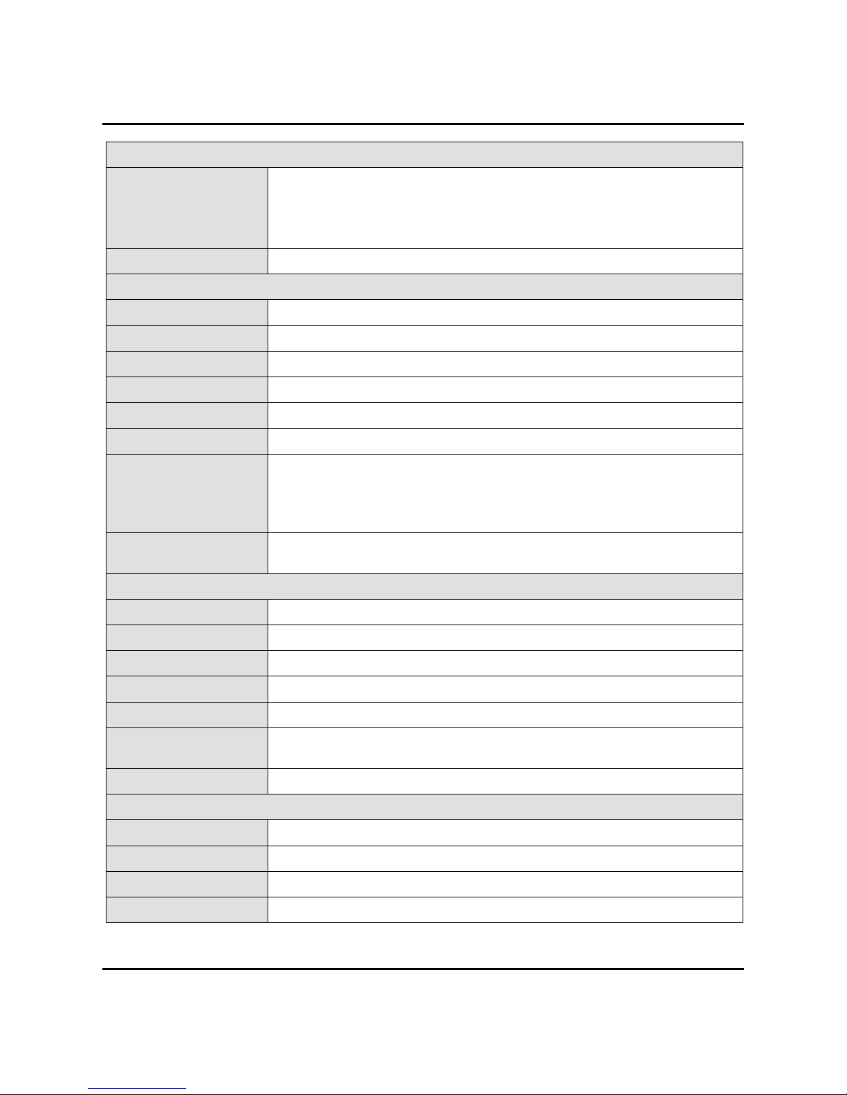
1.1ModelSpecification
System
CPU
IntelGen6Corei7-6600U2.6GHzupto3.4GHz
IntelGen6Corei5-6300U2.4GHzupto3.0GHz
IntelGen6Corei3-6100U2.3GHz
IntelGen6Dual Core3955U 2.0GHz
Memory2xSO-DIMMDDR4upto32GB
LANChipset2xIntelI210-ATand1xInteli219LM
AudioRealtekALC662HDCodeconboard
WatchdogWatchdogTimerSupport,Offer1–255Step
PowerRequirement
PowerInput9V-36VDCPowerInput
PowerProtectionAutomaticsRecoveryShortCircuitProtection
PowerManagementVehiclePowerIgnitionforVarietyVehicle
PowerOffControlPoweroffDelayTimeSettingbyBIOSandSoftware
Battery
InternalBatteryKitfor10MinsOperating(Optional)
*cannot use with optional SIM-6A (6 x SIM card module) in the
same time.
Storage
Type2x2.5”DriveBayforSATATypeHDD/SSD,SupportRAID0,1
1xSATADOM
1.0Introduction
User’sManual Page1‐2
Graphics
Graphics
Intel®HDGraphics520
DirectXVideoAcceleration(DXVA)forAcceleratingVideo
Processing-FullAVC/VC1/MPEG2HWDecode
SupportsDirectX11/10.1/10/9andOpenGL4.0
ResolutionUpto4096x2304@60Hz
I/O
SerialPort4xRS-232/422/485withisolation(AutoDirectionControl))
USBPort2xUSB3.0Ports,2xUSB2.0Ports
LAN3x10/100/1000Mb/sw/M12x-code(1portwithiAMT)
VideoPort2xDPPort,1xVGA(SupportTripleIndependentDisplay)
DIOPort8xGPIand4xGPOwithisolation
Audio1xLine-outand1xMic-in(Line-inOptional)
SIMCardSocket
2xSIMCardSockets,supportedonboardwitheject
6xSIMCardSockets(Optional)
*cannot use with optional Battery backup module in the same
time.
ExpansionBus3xMini-cardslots
2xM.2slot
Environment
OperatingTem p.-40ºC~70ºC
StorageTemp.-40ºC~80ºC
RelativeHumidity0%RH–95%RH
Vibration(random)IEC60068-2-64,random,2.5G@5~500Hz,1hr/axiswithSSD
VibrationOperatingMIL-STD-810G,Method514.6,ProcedureI,Category4
ShockOperating:MIL-STD-810G,Method516.6,ProcedureI,
Trucksandsemi-trailers=15G(11ms)withSSD
CertificationsCE,FCCClassA,EN50155,EN50121
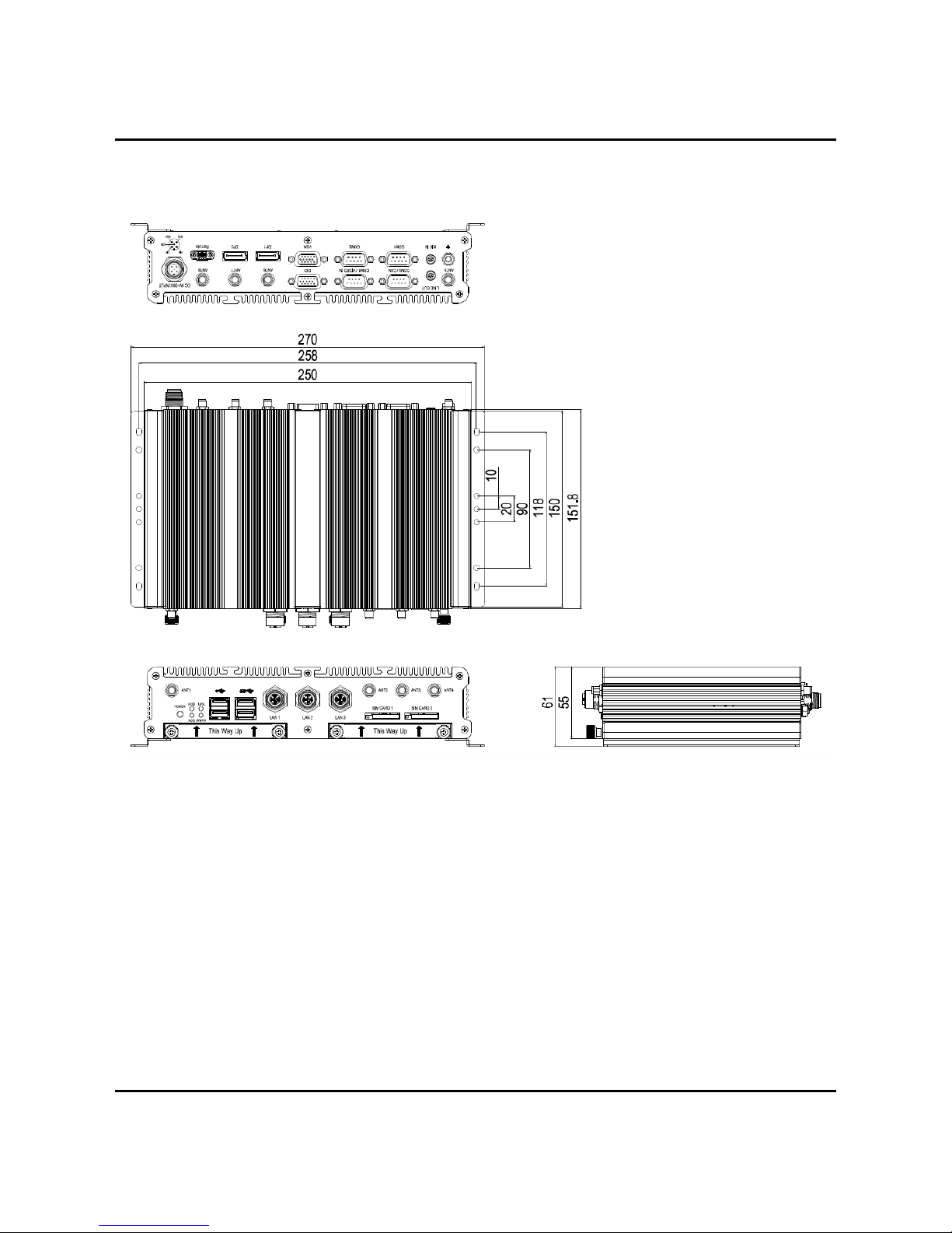
Mechanical
ConstructionAluminumalloy
MountingSupportsbothofwall-mount/VESA-mount
Weight1.9kg(bare-bone)
Dimensions250x150x55mm
1.0Introduction
User’sManual Page1‐3
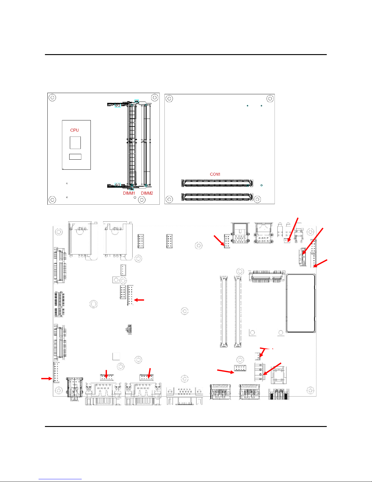
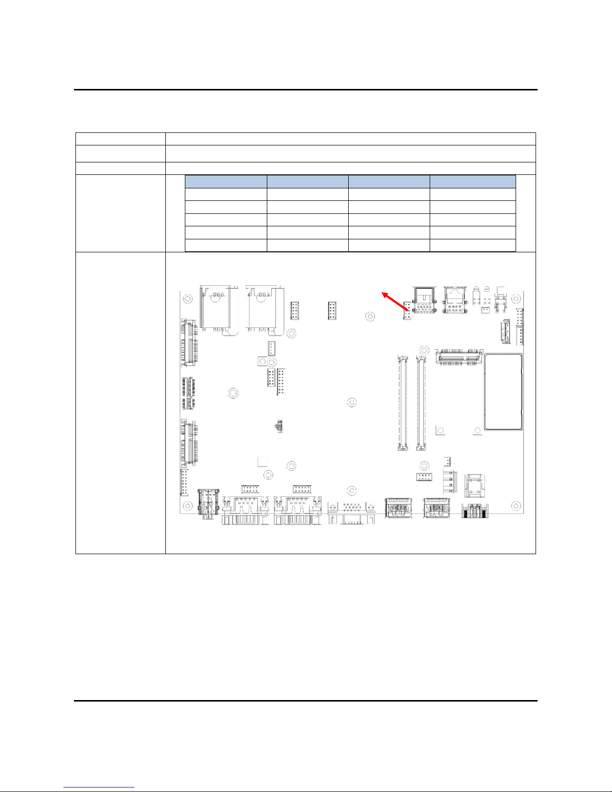
1.2 VBOX‐3620‐M12XIllustration(MB,System)
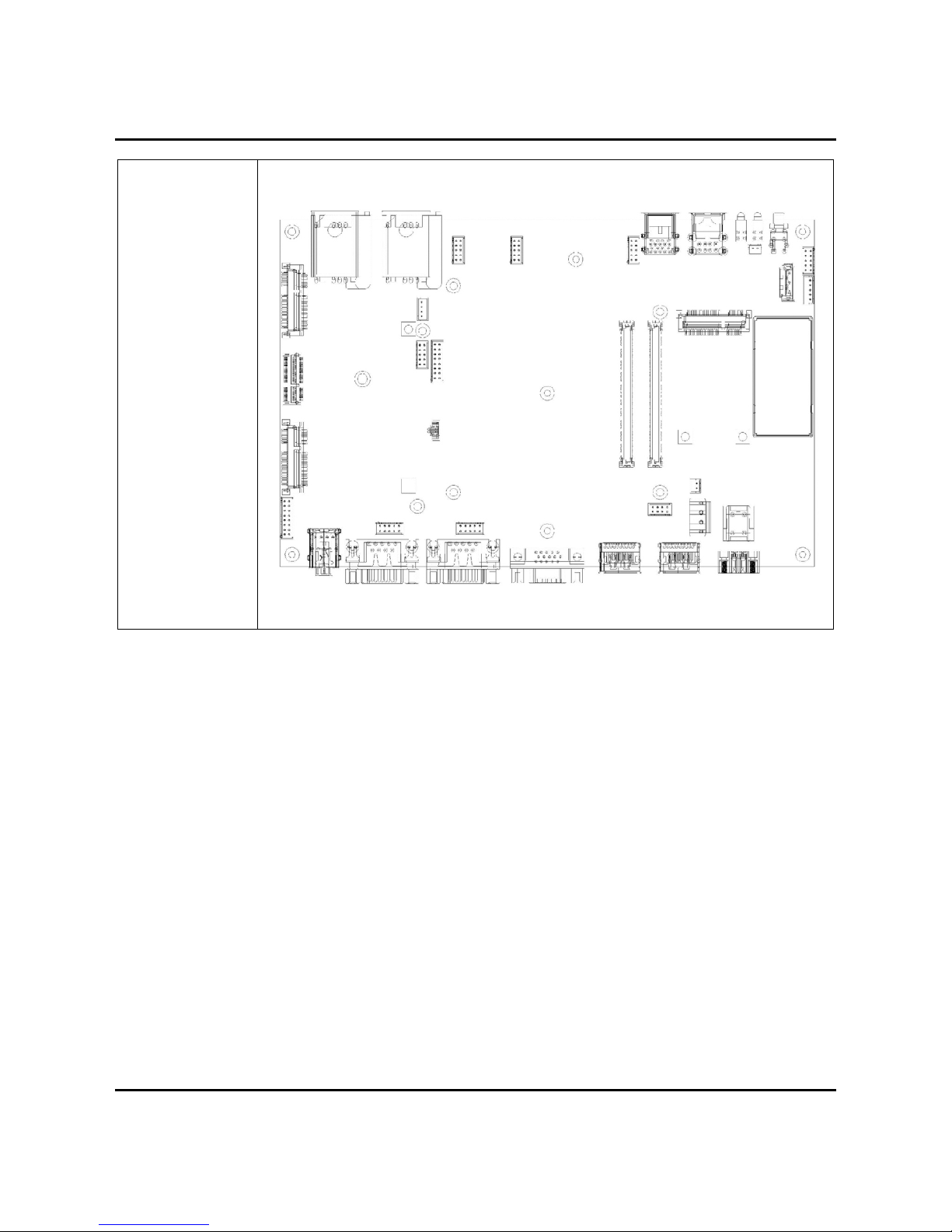
Topviewofmotherboard Bottomviewofmotherboard
LAN1LAN2
USB1
SIM2
MINICARD2
SPWR1
VGA1COM1COM2
COM4COM3
AUDIO1
SIM1
LAN3
USB2
UPS1
SATA3
DP2DP1BTN1
MINICARD1
MINICARD3
M.2
DIO1
JSIM
IGN
USB3
PWR1
1.0Introduction
User’sManual Page1‐4
System
1.0Introduction
User’sManual Page1‐5
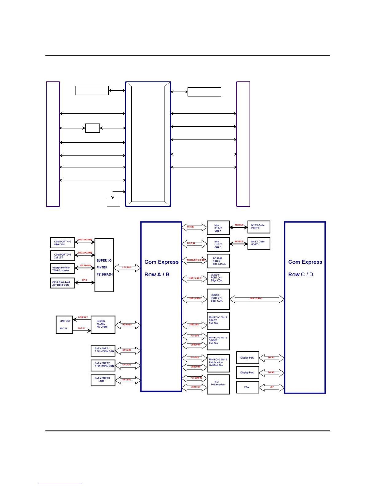
1.3 Architecture
6 x PCIe x1 (Gen2)
(Port 1/2/3/4/6/9)
PHY
I219LM
MDI
(Port 5)
1x PCIe x1 (Gen2)
3 x SATA3
HD Audio
(Port 1~3)
10 x USB 2.0
(Port 1~10)
LPC
SPI
SPI 0
BIOS
DDI 0 (Port B)
DP / HDMI / DVI
4 x USB 3.0
(Port 1~4)
DP / HDMI / DVI
DDI 1 (Port C)
eDP
Generation 6
CPU Intel Core
i7-6600U
i5-6300U
i3-6100U
3955U
Processor
1x PCIe x1 (Gen2)
(Port 10)
AB CD
CHA: DDR4L SO-DIMM NON-ECC
2133 MHz max:8GB
ADD:0XA0
CHB: DDR4L SO-DIMM NON-ECC
2133 MHz max:8GB
ADD:0XA4
Skylake U
CONNECTOR
CONNECTOR
1.0Introduction
User’sManual Page1‐6
1.4 PrincipalcomponentSpecification
CPU
ChipDescription
Intel1. Powerconsumption:
CPUCoreFrequencyTDPUnitTj Cache
i7-6600U2.6GHz15WW100°C4MB
i5-6300U2.4GHz15WW100°C3MB
i3-6100U2.3GHz15WW100°C3MB
Celeron3955U2.0GHz15WW100°C2MB

2.0InternalConnectorSpecification
User’sManual
2.0
INTERNALCONNECTOR
SPECIFICATION
2.0InternalConnectorSpecification
User’sManual Page2‐1
2.0 INTERNALCONNECTORSPECIFICATION
2.1LAN1Connector
Connectorsize10Pin
ConnectortypeJST-2.0mm-M-180
ConnectorlocationLAN1
Connectorpin
definition
PinSignalPinSignal
1LAN1_MDI0P2LAN1_MDI1P
3LAN1_MDI0N 4LAN1_MDI1N
5LGND_CASE6LGND_CASE
7LAN1_MDI2P8LAN1_MDI3P
9LAN1_MDI2N 10 LAN1_MDI3N
Connectormap
LAN1
2.0InternalConnectorSpecification
User’sManual Page2‐2
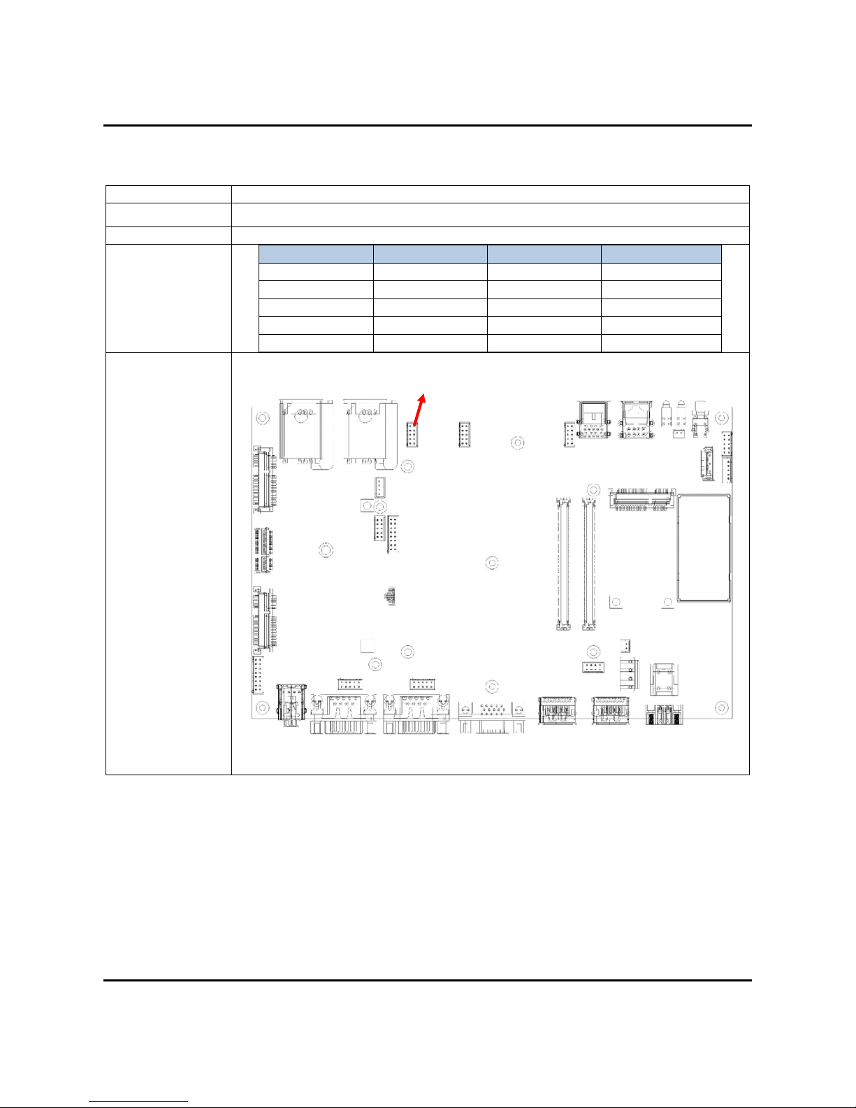
2.2LAN2Connector
Connectorsize10Pin
ConnectortypeJST-2.0mm-M-180
ConnectorlocationLAN2
Connectorpin
definition
PinSignalPinSignal
1LAN2_MDI0P 2LAN2_MDI1P
3LAN2_MDI0N4LAN2_MDI1N
5LGND_CASE6LGND_CASE
7LAN2_MDI2P 8LAN2_MDI3P
9LAN2_MDI2N10LAN2_MDI3N
Connectormap
LAN2
2.0InternalConnectorSpecification
User’sManual Page2‐3
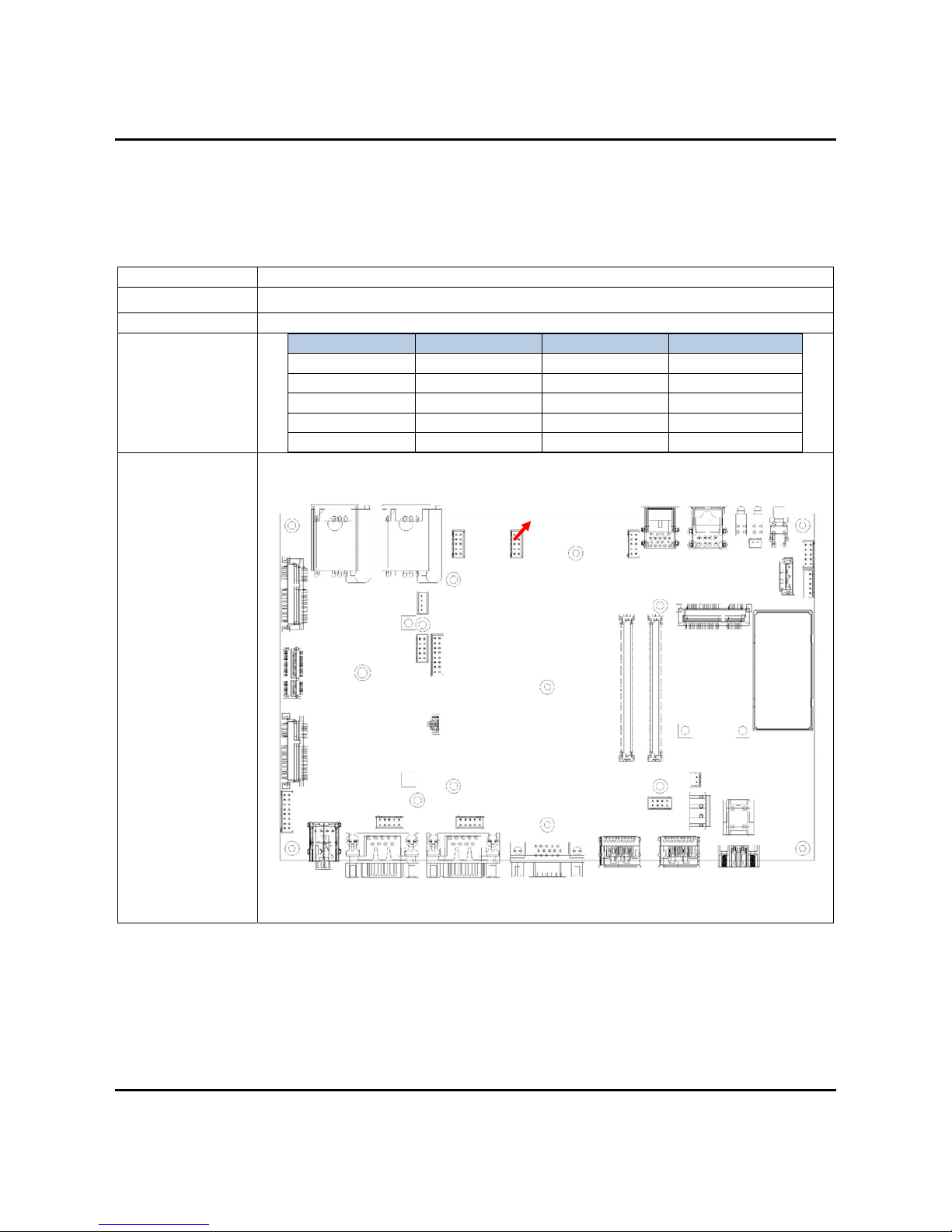
2.3LAN3Connector
Connectorsize10Pin
ConnectortypeJST-2.0mm-M-180
ConnectorlocationLAN3
Connectorpin
definition
PinSignalPinSignal
1LAN3_MDI0P 2LAN3_MDI1P
3LAN3_MDI0N4LAN3_MDI1N
5LGND_CASE6LGND_CASE
7LAN3_MDI2P 8LAN3_MDI3P
9LAN3_MDI2N10LAN3_MDI3N
Connectormap
LAN3
2.0InternalConnectorSpecification
User’sManual Page2‐4
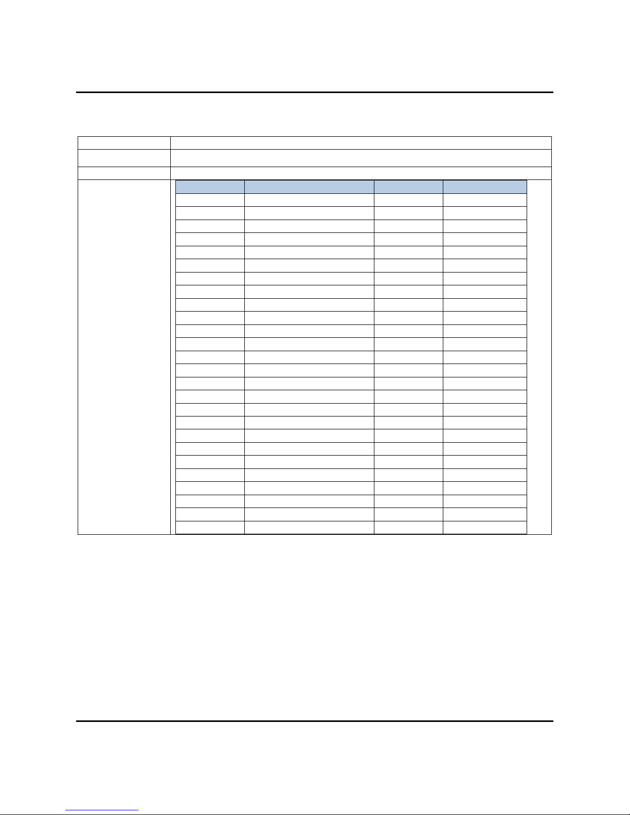
2.4MINIPCI‐EConnector(MINICARD1)
Connectorsize2X26 =52Pin
ConnectortypeMINIPCI-ECON9.2mmH
ConnectorlocationMINICARD1
Connectorpin
definition
PinSignalPinSignal
1PCIE_WAKE# 23VSB
3NC4GND
5NC6NC
7NC8UIM_PWR_A
9GND10UIM_DAT_A
11NC12 UIM_CLK_A
13NC14UIM_RST_A
15GND16NC
17NC18 GND
19NC20MINICARD0_DIS#
21GND22PCIE_RST#
23NC243VSB
25NC26GND
27GND 28 NC
29GND30NC
31NC32NC
33NC34 GND
35GND36USB_4N
37GND 38 USB_4P
393VSB40GND
413VSB42LED_WWAN_A#
43GND 44 NC
45NC46NC
47NC48NC
49NC50GND
51NC523VSB
2.0InternalConnectorSpecification
User’sManual Page2‐5
Connectormap
MINICARD1

2.0InternalConnectorSpecification
User’sManual Page2‐6
2.5MINIPCI‐EConnector(MINICARD2)
Connectorsize2X26 =52Pin
ConnectortypeMINIPCI-ECON9.2mmH
ConnectorlocationMINICARD2
Connectorpin
definition
PinSignalPinSignal
1PCIE_WAKE# 23VSB
3NC4GND
5NC6+1.5V
7MINICARD2_CLKREQ# 8NC
9GND10NC
11PCIE1_MCARD2_CLK_DN 12 NC
13PCIE1_MCARD2_CLK_DP14NC
15GND16NC
17NC18 GND
19NC20MINICARD2_DIS#
21GND22PCIE_RST#
23PCIE1_MCARD2_RX_N243VSB
25PCIE1_MCARD2_RX_P26GND
27GND 28 +1.5V
29GND30SMB_CLK
31PCIE1_MCARD2_TX_N32SMB_DATA
33PCIE1_MCARD2_TX_P 34 GND
35GND36USB_5N
37GND 38 USB_5P
393VSB40GND
413VSB42NC
43GND 44 NC
45NC46NC
47NC48+1.5V
49NC50GND
51NC523VSB
Table of contents
Other Sintrones Desktop manuals

Sintrones
Sintrones VBOX-3000 User manual

Sintrones
Sintrones DSS-1300 User manual

Sintrones
Sintrones SBOX-2110 User manual

Sintrones
Sintrones VBOX-3200 User manual

Sintrones
Sintrones VMT-825 User manual

Sintrones
Sintrones ABOX-5000PG1 User manual

Sintrones
Sintrones SBOX-2600 User manual

Sintrones
Sintrones SBOX-2150 User manual

Sintrones
Sintrones VBOX-3611-4L User manual


 manual")


