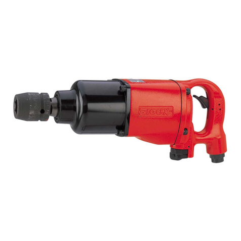
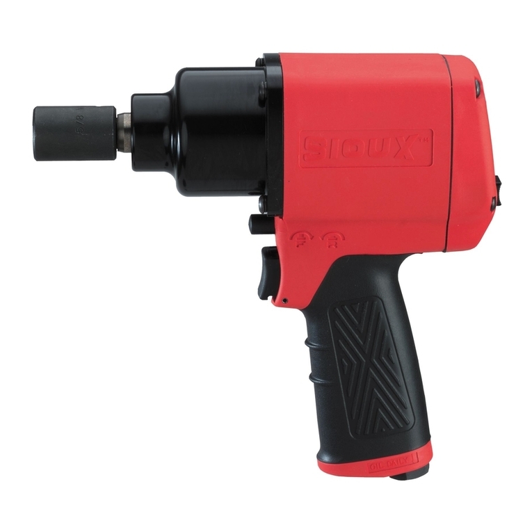
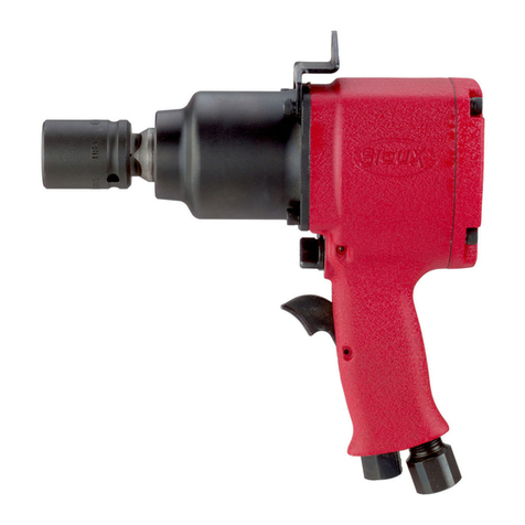
ForeseenUse
Of
TheTool
-
5040
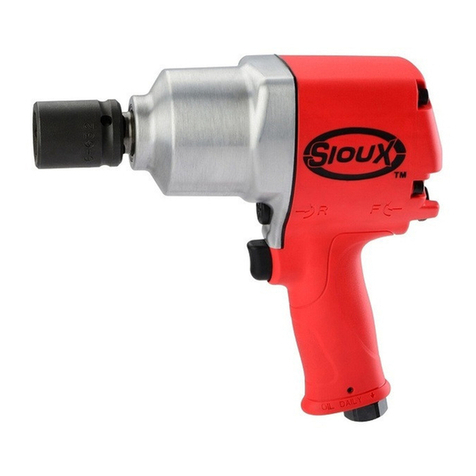
Theimpact
wrench
isdesignedfor the tighteningandImningof threadedfastenerwithinthe range as specifiedby
the
manufacturer.
Itshould
only
beusedinconjunction
with
suitableimpacttype
3W
squarefemaledrive nut runningsockets. Onlyusesockets
whii
are
of theimpact
type.
Itisallwedto
use
suitableextensionbars, universaljoints andsocket adaptorsbeWnthe squareoutput drive ofthe ratchetwrench
and
the
female squaredrive
of
the socket.
Do not use the tool for any other purpose than
that
sptxified without consulting the manufacturer or the manufacturet's authorized
supplier.To do
$0
may
be
dangemus.
Neveruseanimpactwrench asa hammer todislodge orstraightencmssthreadedfasteners. Neverattempttomodifythe toolfor other
usesandnever modifythetdfor
even
itsrecommendeduseas a nutrunner.
Work Stations
The
toolshoutdonlybeusedas a handheld,handoperatedtool.
lt
is
alwaysrecommendedthat
the
toolisusedwhenstadngona
solid
floor.
It
canbeusedinotherpositions,
but
beforeanysuchuse, the operatormustbeina securepositionhavinga firm gripandfooting
andbe aware thatwhen looseningfastenersthe tdcanmequitequicklyaway from the fastener beingundone.An allowancemust
always
be
madefor this rearwardmovement
so
asto avoid
the
possibilityof hand'amhdy entrapment.
PuttingInto Service
Air
Supply
Usea cleaniubtkatedairsupplythatwillgivea measuredair pressureatthetoolof
!XI
PSIG
(6.2
bar)whenthetoolisrunningwiththe
tri~erflW8rfullydepressed. Userecammendedhose Size andlenath.Itisrecommendedthatthetool isconnectedtothe air supplyas
s&minfigure
1.
Do
notconnectthetooltothe air linesystemwithzutincorporatinganeasytoreachandoperateairshutoff valve.-he
airsupply should
be
lubricated.It
is
stronglyrecommendedthat anair filter, regulator,lubricator
(FRL)
is
us&
as shownInFigure
I
as
thii
willsupplyclean, lubricatedair atthe correct pressureto the tool. Detailsof such equipment can
be
obtainedfrom your supplier. If
suchequipmentisnotused, thenthetoolshouklbelubricated
by
shuttingoff
the
airsupplytothetd,depressurizingthelinebypressing
--
the trigger on the td.Diinnectthe air line and pour into the
hose
adaptor a teaspoonful (5ml) of a suitable pneumatic motor
lubricatingoilpreferablyincorporatinga rust inhibiior. Reconnecttoolto air supply and runtdslowly for a few secondsto albw airto
circulatethe oil. Iftool isusedfreauentlv. lubricateon
daii
basisand
if
tool startstoslow orlosemwer.
It
is
recommendedthatWnt tight& &the threadedfasiener assemblybechecked with a torquewrench.
Itisrecommendedthat
the
air pressureat the tool while the tool istunningis
90
PSU6.2
bar.
Operating
Theoutput of the impactwrench inprimeworkingconditionisgoverned
by
mainlythree factors:
a) theinputair pressure;
b) the time the impact wrench isoperatedon the jomt. Normaitime forjoints of average tension requirement
3
to
5
seconds;
c) thesettingof the air regulatorfor aghnjoint at a givenpressureoperatedfora giventime.
The air regulator
(47)
canbe usedto regulatethe output of the impact wrench if no other means of control is available. It is strongly
recommendedthatanexternalpressureregulator, ideallyasparl
of
a
filterlregulatorflubricator
(FRL), isusedtocontrolairinletpressure
so
thatthe pressurecan
be
setto help controlthe tensionrequidtobeappliedtothe threadedfastenerjoint.
There is
no
consistent, reliabletoqueadjustmenton animpact wrench of this
type.
However, the air regulator canbe usedto adjust
tomue to the awmximate tiahtness of a
known
threaded
ioint.
To set the tool to the desired tome. select a nut or screw of known
tightnessof the&me size, t6read pitchandthreadcondiikas those on the job.Turn air regulatoitolow position, applywrenchto nut
andgraduallyincreasepower(turnregulatortoadmitmomair) untilnutmovesslightlyinthedirectionitwas originallyset.Thetdisnow
setto duplicatethattightness, noteregulatorsetting for future use. When tighteningnutsnot requiringcriticaltoquevalues, runnut up
flushandthentightenanaddiionalonequarlertoonehalf turn(&it additionalturningisnecessaryifgasketsarebeingclamped).For
additionalpower neededon disassembly work, turn regulatorto itsfully open position.This impactwrenchisrateda
3/8"
bolt size.
Ratingmustbedowngradedforspring
U
bolts,tiebolts, longcapscrews, doubledepthnuts, badlyrustedconditionsandspringfasteners
as
they absorbmuchof the impactpower. Whenposdtie,clamporwedge the boltto preventspringback.
Soakrustednutsinpenetratingoilandbreakrustsealbeforeremovingwith impactwrench. Ifnutdoes notstartto moveinthreetofive
seconds usea largersize impactwrench. Do not use impact wrenchbeyondratedcapacityas thiswilldrasticallyreducetool liie.
NOTE: Actualtoqueona fastenerisdirectlyrelatedtojoint hardness,toolspeed, conditionof socketandthetimethetoolisallowedto
immct.
usethe simplestpossibletool-to-sockethook up. Everyconnectionabsohenergyandreducespaver.
Thedirectionof mtationof
thii
tool
Is
contmlled
by
the throttlelever.
Be
surethat itis
known
whii
side
ol
the lever hasto
be
pressedto
give the requireddirectionof mtatiinbeforeapplyingthe impactwrenchto thejoint to befastenedor loosened.
For bestresuns:
I)
Always
use
the correct
size
impact
type
socket.
2)
Useextra
deep
socketsinplaceof
extension
barswherepossible.
3)
Do notuseoversized, worn
or
crackedsockets.
4)
Holdthewrenchso
the
socket
fits
squarelyon the fastener.Holdthe wrench firmly, but not too tightly, pressingslightlyforward.
Dismantling
&
Assembly Instructions
Disconnecttool fromair supply.
Pryoff rubbernoseguard
(I)
frommotorhousing
(5).
Removeoilerscrew
(3)
andO-ring
(4)
anddrainoilfromthe frontendintoa suitable
container. Gripthetoolinaviselocatingonthesquaredriveof
the
anvil
(12).
Unscrew
2
screws(50)andremove
2
lock
washers
(49)
and
retainerplate
(48).
Pulloutair regulator
(47)
completewithO-ring
(46)
beingcarefulnotto loseball
(44)
andspring
(45).Tap
pin
(36)
with
asuitablepunchas
fas
aspossibleoutof theassembly,butstillallow the assemblyto mtate. Itisnownecessarytogripthe lengthof the
pindriventhroughtheassembly andpullitouttaking carenotto deformit.
Lift
Offcollar
(37)
andpullout inletbushing
(43).
O-rings
(41)
and
(42)
mayberemovedfrom the stem on inletbushing
(43).
Unscrew
2
capscrews
(39)
and
2
cap screws
(40)
andremovetogether
with
4
lockwashers
(38)
to release
bat#
cap
(30)
andgasket
(29)
fromthe assembly. At thisstage, removethrottlelever
(7)
together with
2
throttiePins
(6).
Fmmbackcapassemblypulloff
2
plungers
(31)
andremove
2
Springs
(32)
and
2
valves
(33).
Itisthenpossibleto lever
out
2
valve seats
(34)
and
2
springs
(35)
takingcareto protect
the
eyesasthe springscanflyoutwhen released. Pullout mtorpin
(22)
andextracttheayemblycomprising
of
retainingring
(28).
rearendplate
(26).
bearing
(27),
mtor
(24),6
mtorblades
(23)
andcylinder
(25).
Noteatthis tlmethe way thecylinder
(25)
irremovedandnotethat itmustbereassembledinthesameway with thechamferonthe
outsidediametertoendface atthefmntendof
the
tool. Removemtor blades
(23)
frommtor
(24),
takeoffretainingring
(28)
andpullmtor
(24)
through rearendplate
(26)
andbearing
(27)
assembly. Usinga suitablepunch, bearing
(27)
may beremovedfromrear
end
plate
(261,
Pulloutfront endplate
(21)
completewithO-ring
(20)
andcarefullypryoffthe O-ring,Removebearing
(17)
andoilseal
(18)
from
front endplate
(21).
Removeretainingring
(19)
frommotorhousing
(5)
and
take
out
the
completehammermechanism.Take off O-ring
(15)
fromcage
(16)
toremovehammer
(14).
2
cagepins
(13)
andanvil
(12).
O-ring
(10)
maybelevered
off
andO-ring
(I
1)
removedfrom
anvil
(12).
oil
seal
(2)
may be
hooked
outof andanvilbushing
(8)
pressedoutof motor housing
(5).
Page
No
2
