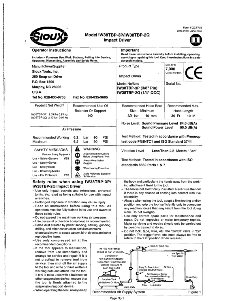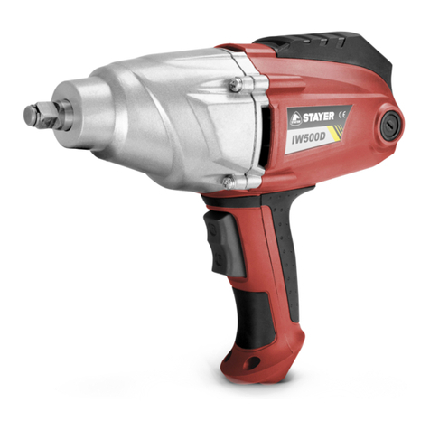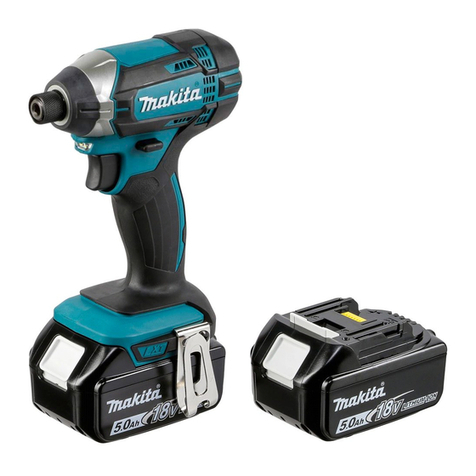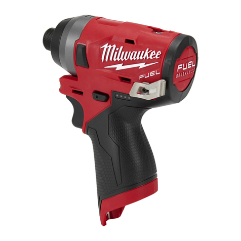
3
Air Compressor
The air compressor should have sufcient capacity to deliver 4.6 cfm (33 SCFM) at 90 psig (6.2 bar, 620 kPa) at each outlet while the tool is
running. The receiver tank should have sufcient capacity to provide surge balance for each air tool.
Air Strainer
An air strainer is built into the removable air inlet bushing located at the rear of the impact wrench. To clean, remove the bushing and use an air
hose to blow dirt and other particles from the screen and bushing.
Before reinstalling the air inlet bushing, check the O-ring for damage. If it is damaged, replace it with a new O-ring to prevent air leakage.
Torque reinstalled air inlet bushing to 50–55 lbs. ft. (68–75 N•m).
Air Supply
The pneumatic impact wrench operates best on clean, moisture-free, well-lubricated air at a constant pressure of 90 psig (6.2 bar, 620 kPa)
maximum.
Piping System
The piping system should be large enough to avoid an excessive pressure drop under maximum ow conditions. All pipe ttings and hose out-
lets should be 1/2" and should be arranged so there are no low spots that collect water which cannot be drained daily. Do not use an air hose
less than 3/8" inside diameter or one that is too long because pressure drop under maximum ow conditions could reduce performance.
Filter
A lter should be used to assure clean air for the air impact wrench. Water, dirt and scale act as abrasives which could damage the air impact
wrench. A lter unit should be installed between the compressor and the air regulator and air lubricator.
Air Regulator
Regulated air pressure is necessary for proper performance of the air impact wrench. The regulator will adjust and maintain the recommended
air pressure of 90 psig (6.2 bar, 620 kPa). Pressure less than this reduces efciency, while pressure greater than this increases blows and
speed beyond the rated capacity—creating potential hazards and possible damage to the air impact wrench. Check the air pressure at the
regulator while using the impact wrench in a normal manner.
Air Line Lubricator
✔ Do not use a heavy grade of oil because stalling and low performance will result.
The preferred method of lubricating the air impact wrench motor is to use an air line lubricator. It should be lled with a good grade of SAE
10W oil.
If an air line lubricator is not used, lubricate the air motor by injecting approximately 1/8 oz (3.75 ml) of air motor oil into the air inlet of the
wrench each day before using it.
Oil Reservoir
The impact mechanism chamber is sealed at the factory and should not require any additional oil.
Forward / Reverse Lever
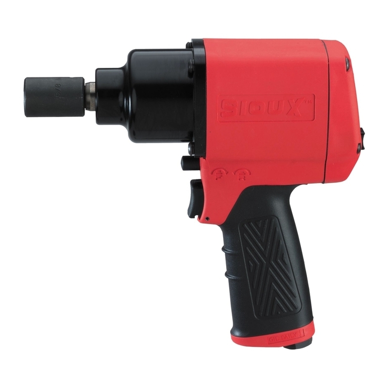
The forward/reverse lever is located in the middle of the wrench above the trigger. For forward (clockwise) anvil rotation, push lever towards
front of tool. For reverse (counterclockwise) rotation, push lever towards back of tool.
Air Pressure
✔ Restricted forward torque, always hand torque to nal specication
WARNING
Restricted torque is dependent on line pressure.
Do not adjust line regulator after tool is set to desired torque.
Socket Retainer
WARNING
Disconnect the air hose before changing sockets.
This air impact wrench features a steel locking ring for retaining all types of impact sockets. The ring holds them in place by friction. It will be
necessary to replace the ring periodically when the force to remove the socket falls below six (6) lbs for a 1/2" square drive.
Specications
Square Drive Size............................................................... 1/2"
Torque
Clockwise ....................................................50 lbs. ft. (68 N•m)
Counterclockwise ....................................285 lbs. ft. (386 N•m)
Recommended Air Pressure......................................................
..............................90 psig (6.2 bar, 620 kPa), maximum
Air Consumption, Free Speed .................... 4.6 cfm (33 SCFM)
Air Consumption, Working .......................... 4.2 cfm (30 SCFM)
RPM, Free Speed CCW ...................................................9,500
Blows per Minute ..............................................................1,400
Air Inlet Thread Size ............................................. 1/4"–18 NPT
Air Supply Hose Size ................................3/8" (9.5 mm) ID min
Maximum Air Supply Hose Length ............................30' (10 m)
Dimensions
Height ............................................................... 7.20" (18.3 cm)
Length............................................................... 7.57" (19.2 cm)
Width ................................................................ 2.18" (5.54 cm)
Weight .............................................................2.88 lbs (1.3 kg)
*Sound Pressure Level .................................................. 95 dBA
*Sound Power Level .................................................... 106 dBA
**Vibration Level ..........................................................5.2 m/s2
Specications at 90 psig (6.2 bar, 620 kPa)
*Tested in accordance with ISO Standard 3744 and Pneurop test
code PN8NTC1.
**Tested in accordance with ISO Standard 8662-7
A–Receiver Tank, Minimum 40 Gallons
(151.5liters)
B–Compressor, Sufcient Capacity
C–Drain, Daily
D–Pipe and Fittings, Minimum 1/2"
E–Top Air Intake
F–Shut Off Valve, Easily Reached
G–Filter
H–Air Regulator, Set at Working Pressure
I–Lubricator
J–Air Tool Connection
K–Low Spot, Water Trap
L–Drain, Daily
Figure 1: Air Supply

