Arzel Heat PumPro Installation instructions

Installation & Operation
Instructions
Arzel®Zoning Technology, Inc.
4801 Commerce Pkwy. Cleveland, OH 44128
Ph: (216) 831-6068 or Toll-Free (800) 611-8312 Fax: (216) 831-6074
www.arzelzoning.com

2
Topic Page
Operating your new zoning system....................................................3
Product Overview...............................................................................4
Installation Instructions.......................................................................5
Board Layout......................................................................................6
Installation & Setup Instructions.........................................................7
Wiring Diagrams.............................................................................8-9
LAT & OAT Sensor Installation........................................................10
Zone Weight Calculation..................................................................11
Leaving Air Temperature Controls...................................................12
Pump Operation...............................................................................13
LCD Display Description..................................................................14
Sequence of Operation....................................................................15
Set-Up Wizard............................................................................16-19
System Commissioning...................................................................20
Remote Emergency Heat Switch.....................................................21
Setup Worksheet.............................................................................22
Bypass Chart...................................................................................23
EzySlide Damper Installation...........................................................24
EzySlide Damper Installation cont...................................................25
EzySlide Damper Installation cont...................................................26
EzySlide Damper Installation cont.& Rectangular Damper Install...27
Did you know? Online Resources..................................................28
Table of Contents
Thank you for choosing the Arzel® HeatPumpro™ zoning system for your comfort and energy efficiency
needs. The HeatPumPro represents the latest in zoning technology. It is designed to both enhance
your system’s performance and deliver just the right amount of heating and cooling to every area of
your home or building.
Please be assured that in addition to the highest in product quality, we are committed to unparalleled
product performance and complete customer satisfaction.

3
Your zoning system is simple to operate and requires no maintenance.
The system will allow you to increase your comfort by directing conditioned air to separate areas (zones)
based upon each zones’ thermostat setting. It provides the opportunity to conserve energy by adjusting the
thermostat setting in unoccupied areas to energy saving levels.
To operate the system, just set or program each zones’ thermostat to your desired comfort and/or set-back
settings. When there is a call for heating or cooling from any zone, the appropriate heating or cooling equipment
will be turned on. The dampers in zones not requiring heating or cooling will close and the conditioned air will
be directed to the calling zone(s) until the thermostat is satisfied.
The system responds to each thermostat on a first-call/ first-serve basis unless your contractor has programmed
an alternate priority approach to deal with concurrent heat and cool calls with your application. The system can
be set to an Automatic Priority (first-call/ first-serve), Heat Priority, Cool Priority or a Zone Weight Priority setting.
Please refer to page 17 or consult your contractor for more details regarding the priority option programmed
for your system.
When there is not an active call for heating or cooling, you may circulate air in individual zones by selecting the
“Fan ON” function on each individual thermostat. The dampers in zones with the fan set to “Auto” will close.
Please feel free to learn more about the installation and operation of the Arzel HeatPumPro by reviewing this
entire manual. Consult your installing contractor with any questions regarding system operation. If
questions are still unresolved, you may call Arzel’s technical support Monday-Friday 8 AM - 5 PM EST.
Please have your system serial number available when you call. Arzel support can be reached by calling
1-800-611-8312.
Simple Operation Assures Comfort
Warranty Registration
REGISTER YOUR WARRANTY AT www.arzelzoning.com/warranty
All Arzel Zoning systems are covered by a limited lifetime parts warranty. The purchasing homeowner is
responsible for activating warranty coverage within 90 days of installation by registering system online at
www.arzelzoning.com/warranty/ Unregistered systems receive one year parts warranty coverage.

4
The HeatPumPro is a non-proprietary, residential and light commercial zoning system, designed for heat
pump or standard heat/cool control. Innovative features provide the opportunity to customize the control to
meet the needs of any forced air system and maximize its efficiency and effectiveness.
Pro-Active Staging
The system will automatically “stage-up” to avoid the feeling of low supply air temperatures when the heat
pumps capacity is not sufficient to provide heated discharge air. The user will not have to wait for the
temperature in the space to continue to fall before the equipment reacts. This feature also reduces or
eliminates the need for two-stage thermostats by measuring outdoor air temperature and controlling the
staging decision based on the calculated heating requirements.
Staging Based upon Zone Weight
The air handler or blower “stages” independently from the compressor and electric auxiliary heaters.
Zone Weight staging of the blower reduces or eliminates the need for a bypass and matches the CFM
to available ductwork. HeatPumPro can also slow the air handler speed to increase latent heat removal
during dehumidification cycles.
Broad Thermostat Compatibility
The HeatPumPro is compatible with any conventional 24VAC thermostat including wireless, auto/manual
changeover, programmable and non-programmable. Zone 1 will accept any heat/cool or heat pump
thermostat. A heat pump thermostat can be used on Zone 1 to provide convenient control of emergency
heat. Zones 2-4 must use standard four or five wire single-stage heat/cool thermostats only.
Humidification and Dehumidification
With the addition of a simple humidistat the HeatPumPro can control a 24VAC humidifier which includes
opening and closing a humidifier bypass damper. It can also control the system to act as a whole house
dehumidifier. Dehumidification with a separate dehumidistat will engage low stage cooling (Y1) with low
stage blower speed (G) and open all zone dampers. When used with equipment that has a
dehumidification function the HeatPumPro simply passes the dehumidify signal from Zone 1 through the
output terminals.
·Additional Built-in Controls
· Full function Dual Fuel control
· Leaving Air Temperature settings (High/Low) provide equipment protection at reduced CFM operation and
stage down capacity control.
·Outdoor Air Temperature sensor provides an outdoor reset function, balance point control, auxiliary resistant
heat lock out and low ambient cooling lock out.
Product Overview

5
INSTALLATION PRECAUTIONS
Read these instructions carefully.
Failure to follow them could damage the Arzel®Zoning System
and/or cause a hazardous condition.
GENERAL SYSTEM OPERATION:
A call from any zone thermostat will initiate HVAC equipment operation and position the solenoid air valve to
open the damper(s) for its zone. The mini pump is energized to automatically activate the dampers, either
open or closed, as required. Vacuum opens the dampers and pressure closes the dampers. When a call is
satisfied, dampers are held in place for 30 seconds after compressor only operations or two minutes after
auxiliary or backup heat operations. This will allow the residual conditioned air to be delivered into last zone
satisfied. The adjustable Secondary Purge Time (0 to 180 seconds) will continue to operate the pump to open
all the zone dampers for a Soft Start on the next cycle.
1. Disconnect the power supply to the HVAC system and the zoning system before making any wiring
connections to prevent the danger of electrical shock or equipment damage.
2. Be sure the HVAC manufacturer’s operating specifications are compatible with the Arzel zoning system.
3. All wiring must comply with applicable electrical codes, ordinances and regulations.
4. Use properly grounded tools, safety glasses and gloves when drilling or cutting sheet-metal ducts,
fiberglass or any hard objects
WARNING
1. The Arzel system is designed for indoor use only.
2. You must touch a grounded metal object before handling the control panel to avoid potential loss of internal
programs due to electrostatic discharge.
3. Install in ambient temperature between 40o F and 140o F in a non-condensing area.
4. Check all system operations after installation is complete.
5. The damper blade gently wipes the inside of the ductwork. Insert a sleeve inside any fiberglass, or
abraidable ductwork, so the blade does not abrade the materials into the air.
6. Leave these instructions with the installed system for future use.
7. There are both AC and DC terminals on the circuit board. Do not intermingle wires.
8. The purpose of the LAT (Leaving Air Temperature) control is to function as an “operating limit”. When set
per the instructions it will add additional capacity control and prevent the equipment from operating outside
the OEM’s speci ications.
CAUTION

6
Board Layout
2
3
4
5
6
7
8
10 11
9
Item # Description Function
1 HVAC Outputs Dry Contacts to control HVAC equipment
2 Lighted LCD Display Provides all system information at a glance & simplies system setup
using a guided Set-Up Wizard
3 USB Port Software revision input and data download to laptop
4 Zone 2 through Zone 4 Inputs Four or ve wire thermostat inputs (Heat/Cool Thermostats Only)
5 Navigation Buttons Provides programming interface for Set-Up Wizard
6 Sensor Inputs Connections for Leaving Air Temperature (LAT) and Outdoor Air Tempera-
ture (OAT) sensors. Both sensors MUST be installed for proper opera-
tions.
7MPS Switch Auto/Manual switch for the Mini Pump
8Zone 1 Input Terminal Inputs for any 24 VAC thermostat, heat pump or heat/cool
9 24VAC Power Input Arzel transformer connections “R” & “C” (40VA)
10 2-Amp Fuse Protects the board against thermostat wiring shorts
11 Power Switch Controls 24VAC power source to zone control panel
1

7
Installation & Setup Instructions
1. Install Dampers/Run Tubing
Dampers install directly into new or existing ductwork. Orient the tube connection port so it is pointing up-
stream (toward the equipment). Install one main tubing run for each zone. Use connection “T’s” for multiple
dampers in a zone. Arzel recommends using a different color tube for each zone. Note: Dampers should not
be concealed behind a permanent barrier such as drywall without an access panel.
2. Mount Control Panel
The control panel must be mounted vertically on an exterior wall to reduce noise. The wall must also
be located in a non-condensing area where temperatures will not normally exceed 140º F. DO NOT
MOUNT PANEL ON DUCTWORK OR THE HVAC EQUIPMENT. The best method is to attach a piece of
3/4” plywood to a stud wall or foundation. Hold the panel level on the wall and mark the positions of the
upper mounting holes. Drive two screws into the wall leaving the heads at least 1/2” out. Set the panel over
the screws. Drive two screws into the lower mounting holes. Tighten the upper screws.
Note: Prior to making electrical connections, touch a mechanical ground to discharge static electricity.
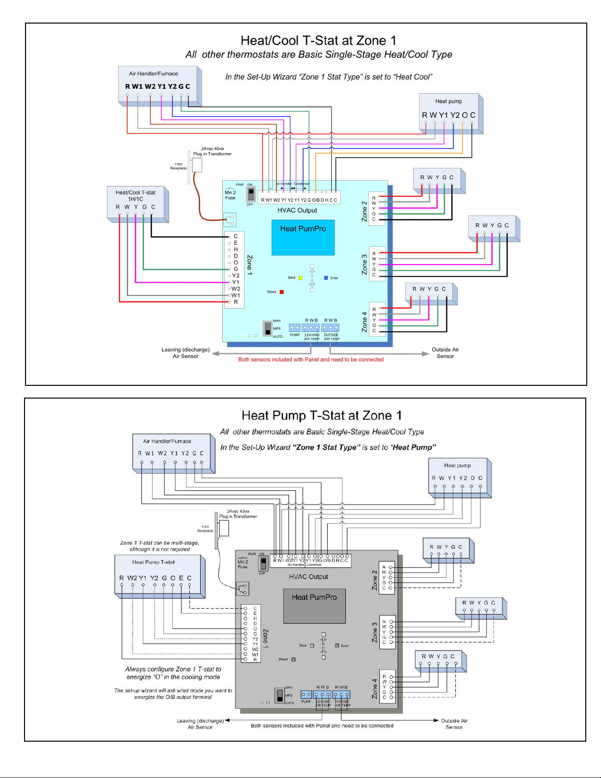
3. Connect Thermostats
Install a thermostat for each zone observing the terminal designations. Use 18 gauge, multi-conductor, solid
thermostat wire to connect the thermostats to the control panel. When using a heat pump thermostat in Zone
1, “O” must be set to energize for cooling calls. Zones 2, 3 and 4 must be non-heat pump models. Document
the location of each thermostat connected to each zone on the “Zone Layout” label on the side of the panel.
4. Connect Equipment
Use 18 gauge, multi-conductor, solid thermostat wire to connect the HVAC outputs located along the top of the
zone control panel to the HVAC equipment. Connect Y1, Y2 “Air Handler” to the blower or furnace controls
and the Y1, Y2 “Condenser” to the heat pump/air conditioner controls. The two “C” terminals are for connection
between the furnace/air handler transformer and the common circuit of the heat pump/air conditioner controls.
5. Connect Transformer
Use 18 gauge, 2-conductor solid wire to connect the R and C power input terminals to the mounting screws on
the 40VAC self-resetting, plug-in transformer supplied with the Arzel Zoning System. Plug in the transformer
to any standard 120VAC receptacle. Note: If you elect to not use the provided transformer your warranty
may be void. Additional surge protection is recommended.
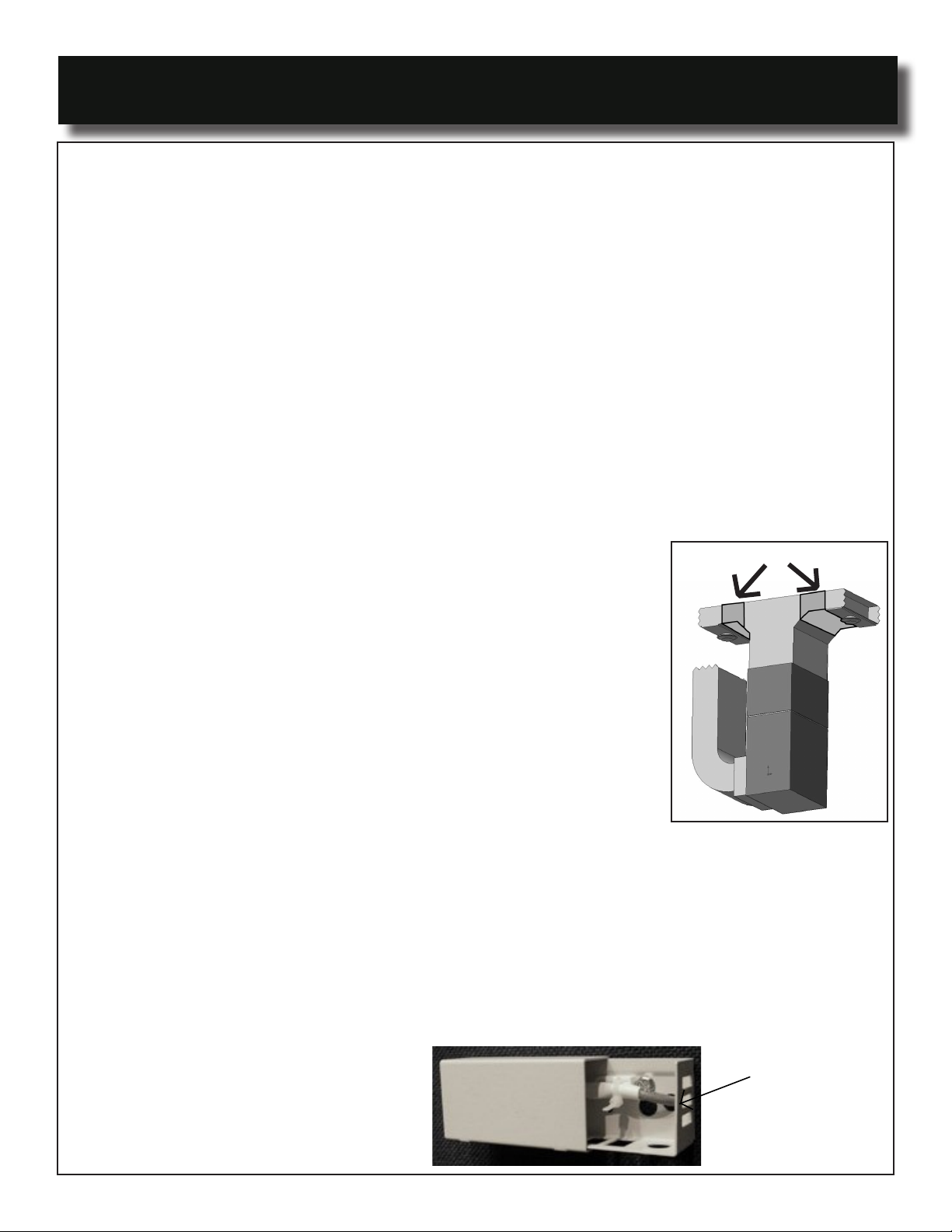
6. Connect Sensors
1. Install the leaving air temperature sensor in the supply duct 12 to 18 inches from the plenum and
before any dampers.
2. Install the Outdoor Air Temperature sensor outdoors, preferably on the north side of the house,
not in direct sunlight.
3. Wires must be connected to corresponding terminals, R-red, W-white and B-black.
7. Turn on Panel and Run the Set-Up Wizard

8

9

10
OAT Sensor Installation
1. Choose a location:
• Out of direct sunlight
• Above maximum snow level
• That is accessible should service be required
•Preferably on the north side of the house is preferable
2. Drill a 5/16” access hole through the exterior wall aligned with one of
the pre-drilled holes on the back of the enclosure body. If the sensor
wire is to run along the outside of the structure, use opening located
at the bottom of the enclosure.
3. Mount the sensor enclosure level over the access hole with the
sensor opening on the back plate aligned with the 5/16” opening.
Fasten with appropriate screws being cautious not to over tighten,
flexing the box out of square.
4. Route the sensor lead into the sensor enclosure and fasten with the provided wire tie.
5. ALTERNATIVE SENSOR MOUNTING
• Sensor can be mounted inside the control section of the outdoor condensing unit.
• Ensure sensor is mounted in a location where its temperature reading will not be
influenced by the equipment
An OAT sensor enclosure is provided to protect the outdoor sensor from physical damage as well as snow,
ice and solar heat inuence.
LAT & OAT Sensor Installation
Installation Notes
• Both sensors are identical and can be used as either the Leaving Air Temperature (LAT) or Outside Air
Temperature (OAT).
• Both sensors must be connected to the board for proper functionality, non-heat pump applications do not
require the OAT sensor to be located outside.
• If additional wire length is required on a sensor, up to 50 ft of 18-3 thermostat wire can be added.
• Keep panel power “off” while connecting sensors to the board.
• The sensors have three conductors, (red, white, black) and must be wired to the appropriate (R, W, B)
terminals of the respective sensor terminals.
LAT Sensor Installation
• The sensor must be located in the supply trunk, downstream of the heat exchanger and cooling coil and
before any trunk dampers.
• Do not locate the sensor in an area that is in the direct line of site of the heat exchanger, cooling coil or UV
Lights. These locations can cause false readings.
Sensor location here
Cover
Outdoor
Air Sensor
<--slide -->

11
Zone Weight Calculation
A H Threshold Set-Point Stage-up occurs when:
100% All 4 Zones call together
80% Zones 1, 2 & 4 call together
70% Any 3 Zones call together
55% Zone 2 with either 1 or 4 call together
Zone weight settings should provide maximum airflow to zones calling, without creating objectionable air noise
at the registers. Since many systems serve a single zone the majority of the time, low stage energy savings
will be achieved.
Y2 (High Stage) blower and W2 (High Stage) FF Furnace capacity will be engaged any time the
accumulated, served zone weight is equal to or greater than the AH Threshold setting in the Set-
Up Wizard.
Alternate “AH Threshold” setting for the above example:
The following is an example of “Zone Weight” and “Air Handler Threshold” set-up to demonstrate the functionality
behind the settings you choose.
The application below is a two story home being served by four independent zones. The zone
weights are determined by simply dividing the number of runs in each zone by the total number of
runs in the system. Total zone weight does not need to add up to 100% and may, in fact, be over
or under weighted to produce the desired results.
Zone 1 Living area, 1st Fl (5-6” runs/20 = 25%)
Zone 2 Living area, 1st Fl (6-6” runs/20 = 30%)
Zone 3 Master Bdrm Suite, 2nd Fl (4-6” runs/20 = 20%)
Zone 4 Bedrooms, 2nd Fl (5-6” runs/20 = 25%)
Total: 20-6” runs

12
LAT & OAT Sensors
The HeatPumPro uses both Leaving Air Temperature (LAT) and Outside Air Temperature (OAT) sensors to protect
the HVAC equipment and proactively choose the most appropriate mode of operation.
BOTH SENSORS MUST BE INSTALLED FOR PROPER SYSTEM OPERATION
High and Low limit protection:
There are individual high end set-points for Heat Pump heating, auxiliary heat (or FF furnace) and low temperature
operating limits for cooling.
The LAT ensures that the HVAC equipment will always be operated inside the OEM specifications.
The LAT functions in a staged-manner:
As soon as the LAT exceeds the operative limit the equipment is staged down.
If the LAT stays outside acceptable limits for three (3) minutes then it will cycle off the equipment, leaving only
the fan running.
Proactive Staging:
The HeatPumPro can handle up to four stages of heating (two-stage heat pump with two stages of electric heat
strips or two stages of gas furnace operation). It handles two stages of cooling. The HeatPumPro manages all
staging with single stage inputs from all thermostats.
Staging is managed by continually comparing the Leaving Air Temperature to field adjustable heating and cooling
thresholds. If the system is not maintaining the appropriate temperature then it will automatically stage up. If it
starts to move to the extremes then it will stage down. The table below outlines how the system stages.
The Decision Points (HST, CST, and AHST) are all adjustable through the Setup Wizard. The contractor is
responsible for choosing appropriate staging settings. Multistage thermostats are not required. The HeatPumPro
will stage up as required to maintain the amount of cooling or heating that is required by the space based on the
Leaving Air Temperature and the Outdoor Air Temperature. It will stage the blower (Multi/Variable Speed Motors)
according to the Zone Weight of the ductwork being served.
HVAC
Equipment
Decision Point Function
HeatPump
Heating
Heat Stage
Threshold (HST) at
or above 30oF OAT
Minimum acceptable temperature in the plenum. If the system cannot
maintain HST then it will automatically stage up.
Note: If the OAT drops below 30ºF, the HST rises 1/2 ºF for every 1ºF
below 30ºF. So the system will stage more aggressively on colder
days.
Fossil Fuel
Furnace
Auxiliary Heat
Strips
Multi/Variable
Speed Blowers
Air Handler
Staging
Threshold (AHST)
For Aux heat or Furnace Operations, the system Stages up and down
based upon the AHST. If the system is serving more zone weight
than the AHST it will stage up. If it is serving less than AHST then it will
stage down.
Airflow with multi/variable speed systems is controlled in the same
manner.
HeatPump A/C
Cooling
Cool Stage
Threshold (CST)
Maximum acceptable temperature in the plenum. If the system
cannot maintain CST then it will stage up to high stage automatically.

13
AIR PUMP OPERATION
Both pumps will start and position up to 30 dampers any time there is a call for heating, cooling or
fan operation. Both pumps will stop three minutes after the last thermostat is satisfied. Pumps
will restart for any call for heating, cooling or fan from any thermostat. Both pumps are delayed
one minute on a call for heat (fossil fuel) to allow the blower to start before any dampers close.
Pumps are designed for continuous duty.
MANUAL PUMP SWITCH (MPS™)
The Manual Pump Switch (MPS) (Fig. 12b) is provided to test the damper system and to bypass
the zoning system in case of a board emergency. This switch will start the pumps manually
and with the “Power” switch in the OFF position, all the zone dampers will open. This will aid in
troubleshooting by allowing the operation of the HVAC system independent of the Arzel panel, if
you suspect a PC board failure.
YOU CAN BYPASS THE ZONING SYSTEM BY FOLLOWING STEPS BELOW:
1. Turn the Arzel PWR switch off. You must keep this switch in Off position to block ALL
zone thermostats from calling for service and placing all the zone dampers in the
normally open position.
2. Disconnect the wires from any one zone thermostat terminal and connect them to the
HVAC Output terminals.
3. Turn the MPS switch to manual position.
The HVAC equipment will now be controlled by the one thermostat connected to the Output
terminals. The pumps will run continuously, holding ALL the zone dampers open.
Fig. 12b
Arzel Panel
Pump Operation

14
The Liquid Crystal Display (LCD) on the HeatPumPro is your portal to customizing your zoning installations.
The set-up options allow you to design the control sequence in the best interest of your customer, balancing
energy usage with comfort delivery while maintaining safe equipment operation. These options can give energy
cost priority over comfort, maximum air delivery over noise suppression or fossil fuel priority over heat pump
operation. To access the Set-Up Wizard screen push the red “Reset” button just beneath the LCD,
then press the blue “Enter” button.
The LCD screen on the HeatPumPro provides a simple way to view system operations. Once the operating
parameters are set in the Set-Up Wizard, the LCD display will default to the “Main Operations” screen shown
below.
LCD Display Description
Sum of “Zone Weight(s)” for served
zone(s)
Leaving air temp. in
supply duct
Operating software version
Pressing the blue “Enter” button accesses the “Set-Up Wizard”
1.27b
CON A H
OUT W1 W2 Y1 Y2 Y1 Y2 G O D
OAT 65 LAT 72
COMP
LOCK 1 2
ZONES
1 3 WT% 70 - - : - -
HVAC
PURGE TIME
BLUE BTN : NXT SCRN
Outputs to condenser
Energized output(s) to
equipment
Outdoor ambient
temperature
Zone(s) being served
Outputs to air handler
Compressor stages in a
4 min timed off cycle
Time remaining for the
“Post Purge” cycles
The HeatPumPro has the ability to detect input signals from zone thermostats that do not make sense
and provide a visual “ILL” (illegal) call indicator on the LCD screen. By pushing the blue “Enter” button on the
board you can see what each zone is calling for and if that signal falls into the illegal category. Pushing the blue
“Enter” button past the last zone will show you any “Messages” regarding staging occurrences, Balance Point
status and LAT limit functions.
Status Message Menu
Below Balance Point - OAT is below the set “Balance Point”, back-up heat will be utilized
Capacity Stage-Up - Board logic has staged up to the next level of capacity
Resistance Lockout OAT - OAT is above the “Aux Lock” temperature setting, Aux Heat is locked out
LAT Stage Down - LAT above “HP LAT Htg Limit”, staged down one level of capacity
Dehum Off Cycle - Dehumidification cycle is in a “timed off period” to prevent overcooling of space

15
On a Call for Heat:
1. The thermostat will send the appropriate signal to the circuit board.
Zone 1= Y1, G or W
Zone 2,3,4=W
2. The control panel pump will start and de-energize the solenoid for the zone that is calling.
3. The HeatPumPro will consider the Balance Point (BP) setting if auxiliary heat is fossil fuel or Aux
Balance Point is set to True:
a. If the OAT is above the BP setting the Y1 and G signal will be sent to the air handler and a Y1
signal will be sent to the condenser (O/B will also be energized if set for Rev Valve Energized
in Htg mode).
b. If the OAT is below the BP setting then W1 will be energized to initiate back-up fuel operation,
W2 will be controlled by the zone weight logic.
c. If the BP setting is set for “Lock in Backup Heat” then all heat calls will be served with a W1
output (fossil fuel) regardless of the OAT. W2 will be controlled by the zone weight logic.
4. The LAT sensor will start to monitor the air in the supply plenum. The sensor will be looking for the
temperature set for the "Heat Stage Threshold" in the Set-Up Wizard plus an OAT adjustment. The
threshold temperature will raise 1˚ for every 2˚ drop in OAT below 30˚F.
Ex. HST = 100˚F in Set-up Wizard:
30˚F OAT 100˚F LAT threshold
20˚F OAT 105˚F LAT threshold
5. The LAT sensor will continue to monitor the supply air temperature. If the temperature levels off below the
heat stage threshold setting for more than three minutes, the HeatPumPro will send a signal to Y2 on the
condenser.
6. The LAT sensor will continue to monitor the supply air temperature and continue to stage up until all stages
of heat are on or the heat stage threshold temperature is met. With an all electric system the HeatPumPro
will stage the electric heat on with the heat pump running, with a fossil fuel backup it will turn off the heat
pump and run the back-up heat only when a W1 or W2 signal is sent.
7. If the temperature in the supply plenum reaches the auxiliary high limit it will begin to stage down the
equipment while still maintaining a temperature above the Heat Stage Threshold.
8. When the zone is satisfied the equipment will turn off, the zone will stay open for two minutes and then run
the pump for the time set in the secondary purge time in the Set-Up Wizard to open the rest of the dampers
and allow for a “soft-start” on the next cycle.
On a Call for Cooling:
1. The thermostat will send the appropriate signal to the circuit board: Y1, G, O or Y1, G for zone 1
depending on the thermostat type; Y, G for zones 2, 3, or 4.
2. The pump will start and de-energize the solenoid for the zone that is calling.
3. The Y1, Y2, G signal will be sent to the air handler if the "Air Handler Stage Threshold%" (AHST) is met.
Otherwise, only Y1, G will be sent to the air handler. A Y1 signal will be sent to the condenser, and an O/B
will be sent if set for Rev Valve Energized in Cooling.
4. The LAT sensor will monitor the supply air temperature in the plenum and look for the temperature set in the
cool stage threshold in the Set-Up Wizard. If the LAT sensor senses a continuous decrease in temperature
it will leave the system in first stage cooling.
5. If the LAT sensor senses the supply air temperature leveling off below the setting it will start a three minute
timer. If the supply temperature does not reach the setting in three minutes it will send a Y2 signal to the
condenser.
6. If the supply air temperature reaches the cooling low limit setting the signal to Y2 will be removed.
7. When the zone is satisfied the equipment will turn off, the zone will stay open for 30 seconds and run the
pump for the time set in the secondary purge time in the Set-Up Wizard to open the rest of the dampers
and allow for a “soft-start” on the next cycle.
Sequence of Operation

16
Set-Up Wizard
To access the Set-Up Wizard for the HeatPumPro conrm that the Power Switch is “ON”, then press the red
“RESET” button and immediately press the blue “ENTER” button while the start up screen is active. Use the
white UP and DOWN buttons to change Options within each Category. Below are the setup categories in the
order they appear in the software. The Setup Worksheet in the back on the manual can be used to document
your settings.
All settings are held in memory even when power is interrupted. To view options or make changes after initial
setup, simply press the red “RESET” button and proceed through the setup categories, making any necessary
changes, using the white “UP” and “Down” buttons.
Parameter Description Options Factory
Default
Show Temperature in Determines the temperature display scale on the HeatPumPro. Fahrenheit
Centigrade
Fahrenheit
Priority Allows specified mode to interrupt active cycle. Priority options
include- Automatic, Heating, Cooling, or Zone Weight Priority.
In Automatic Priority: Auto priority will allow the first call
(either heating and cooling) to establish the priority
sequence for this cycle. A heating or cooling call will
always override fan-only operation. Any zone can initiate
constant fan if no other zone has a demand for either heating
or cooling.
In Zone Weight Priority: Zone Weight priority allows the
call in the largest weighted zone(s) to have priority over any
opposing calls in the smaller zones. The board continues
that call until the largest weight zone is satisfied or the
opposing call becomes the larger zone.
In Heating Priority: Heating priority allows heating to
have priority over cooling. Any zone calling for heating
will be served immediately; if a cooling cycle is in process
it will be terminated. The mode being served will be limited to
a 20 min. cycle.
In Cooling Priority: Cooling priority allows cooling to have
priority over heating. Any zone calling for cooling will be
served immediately if no other zone wants cooling. Any
zone can have constant fan, if no other zone wants cooling
or heating.
Note: In Heating, Cooling and Automatic Priority the board
will serve the priority caller for 20 minutes then the opposing
call for 20 minutes and rotate until all calls are satisfied.
Automatic
Zone Weight
Heating
Cooling
Automatic

17
Zone 1 Stat Type Type of T-Stat used on Zone 1
Enter the type of thermostat you are connecting to Zone 1
of the HeatPumPro panel.
Heat Pump or
Heating/Cooling
Heat Cool
Zone 1 Weight % Zone 1 relative weight
Enter the percentage of available ductwork to system
capacity in each zone. Ex. Calculate nominal CFM for the
zone and divide by total system capacity. This can also be
used to set priority to a specific zone by giving it a larger
weight. Sum of zones does not need to equal 100%.
10-90%, 5% 50%
Zone 2 Weight % Zone 2 relative weight 10-90%, 5% 50%
Zone 3 Weight % Zone 3 relative weight 10-90%, 5% 50%
Zone 4 Weight % Zone 4 relative weight 10-90%, 5% 50%
AH Stage-up
Threshold %
Air handler Stage-up threshold, Y2 output to Air Handler or
W2 to FF Furnace engaged when threshold % is reached
Set the percentage of ductwork you would want to be
open before the HeatPumPro panel will send a Y2 signal
to the air handler to increase capacity or W2 signal to
furnace to increase output capacity.
30-100%, 5% 50%
Heat Stage Threshold Min leaving air temp (LAT) required for comfort at 30º F outside air
temperature (OAT). This set-point adjusts by 1º for every 2º change
in OAT.
Sets the minimum supply air temp in the heating mode. At the
factory default the HeatPumPro will maintain a 88º supply air temp
at 30º F outdoor temperature. The supply air temperature will raise
or lower a 1º F for every 2º F change in outdoor temperature.
80-130 degrees F,
1 degree increments
88 degrees F
Cool Stage Threshold Max cooling supply air temp, Y2 is energized if this LAT is not
reached with Y1 output
Sets the maximum supply air temperature allowable before
bringing on second stage cooling. Does not reset with OAT.
20-60 degrees F,
1 degree increments
55 degrees F
Balance Point OAT
Set to “Lock in
Back-Up” for
Non-Heatpump
applications
Heat pump operates above BP set point and FF furnace operates
below set-point
Set the outdoor temperature at which you want to lock the
heat pump out and have the fossil fuel back up to take over
on a call for heat. This setting is overridden by the “Heat
Stage Threshold” function.
0-50 degrees F,
1 degree increments
or “Lock in Back-up
Heat” for
non-Heat Pump
applications
Lock-in Back
Up Heat
Resistance Lockout
OAT
Aux Heat (Elect Resistance) will be locked out when OAT exceeds
this setting
Set the outdoor temperature at which you want to lock out
the electric resistance heat.
0-40 degrees F,
or “Lock in Aux”
To allow elect aux
heat staging
regardless of OAT
30 degrees F
HP LAT High Limit High limit of heat pump leaving air temperature
Set the maximum allowable supply air temperature in heat
pump mode.
100-125 degree F,
1 degree F steps
120 degree F
AUX.LAT High Limit Aux “W” output leaving air temp high limit
Set the maximum allowable supply air temperature in fossil
fuel or electric resistance heat operation.
130-180 degrees F,
1 degree F steps
140 degree F
Parameter Description Options Factory
Default

18
Cooling LAT Low Limit Cooling leaving air temp low limit
Set the minimum supply air temperature in the cooling
cycle to prevent the coil from freezing.
34-46 degrees F,
1 degree F steps
42 degrees F
Type of back-up Specify type of Aux “Back-Up” heat
Select the type of heat that will be initiated when the heat
pump can no longer maintain the setting of the heat stage
threshold.
Electric or Fossil
Fuel
Fossil Fuel
Back-up controls fan G output for fossil fuel heat operation True=”W” False=”W”, “G”
Select true if the back-up heat source controls the fan
internally or false ifthe Heat PumPro needs to initiate the
fan.
True or False True
Dehum Caller
Voltage
Required voltage to energize a dehumidification call. (Note:
Leave setting at 24v when not used.)
Set to the dehumidifcation control voltage out put on the
dehumidistat control, Y
0 Volt or 24 Volt 24 Volt
Secondary Purge Time End-of-cycle purge time to diffuse residual heating or cooling
Set the amount of time in seconds to run the pump after a
cycle to open all the dampers. Typically 5 seconds per
damper.
0-180 seconds, 10
sec increments
60 seconds
Dehumid Cycle Time Dehumidification “On Cycle” time limit to prevent over-cooling of
space once cooling set-points are reached (off cycle is fixed at
10 min)
Set the maximum “ON” time for the dehumidification cycle to
prevent over cooling of the space. The “OFF” cycle is set at
a fixed time of 10 minutes.
5-15 minutes, 5
minute increments
10 mintues
CLG Low Ambient
Lock
Minimum OAT that mechanical cooling is allowed to operate (locks
out Y output)
Set the outdoor temperature at which the cooling will no
longer come on.
20-60, 1 degree F
increments
50 degrees F
Rev Valve Energized Heat pump rev valve energize in heating or cooling (Zone 1 HP
stat always callls “O” for clg call”)
Set the mode in which the reversing valve is energized.
Note: If the heat pump thermostat has a setting for
reversing valve in the configuration mode, set the
thermostat to energize the reversing valve in cooling.
Cooling or Heating Cooling
Use Bal Pt for Elec Allow Balance Point to be used on all electric system. True heat
pump will shut down when ODT is below Balance Point setting.
True or False False
Demo Mode EnabledDemo mode speeds up all timing sequences by a factor of 12.
Used for demonstrations and for initial system commissioning.
True or False False
Parameter Description Options Factory
Default

System Type System Type System Type System Type System Type System Type
HPP Options Single Stage FF/C Multi Stage FF/AC Multi Stage Dual Fuel Single Stage HP W/Elec Multi Stage HP W/Elec Duel Fuel /w Inverter HP
F or C Fahrenheit Fahrenheit Fahrenheit Fahrenheit Fahrenheit Fahrenheit
Priority Automatic Automatic Automatic Automatic Automatic Automatic
Zone 1 Stat Type Heat/Cool Heat/Cool HP or H/C HP or H/C HP or H/C HP or H/C
Zone 1 Weight Default N/A set as needed set as needed Default N/A set as needed set as needed
Zone 2 Weight Default N/A set as needed set as needed Default N/A set as needed set as needed
Zone 3 Weight Default N/A set as needed set as needed Default N/A set as needed set as needed
Zone 4 Weight Default N/A set as needed set as needed Default N/A set as needed set as needed
AH Stage Threshold Default N/A set as needed set as needed Default N/A set as needed set as needed
Heat Stage Default N/A Default N/A 88 88 88 80
Cooling Stage Default N/A 55 55 Default N/A 55 55
Balance Point Lock-in Lock-in 30 Default N/A Default N/A *Set as required*
Resistance Lockout Default N/A Default N/A Default N/A Lock In Lock In *Set Equal to Balance Point*
HP High Limit Default N/A Default N/A 120 120 120 120
Aux High Limit 140 140 140 140 140 140
Cooling Low Limit 42 42 42 42 42 42
Backup Fuel Type Fossil Fuel Fossil Fuel Fossil Fuel Electric Electric Electric
Backup Control Fan TRUE TRUE TRUE FALSE FALSE TRUE
Dehum Voltage 24 24 24 24 24 24
Secondary Purge 60 60 60 60 60 0
Dehum Cycle Time set as needed set as needed set as needed set as needed set as needed set as needed
CON Lockout Temp 50 50 50 50 50 50
Rev Valve Energized Default N/A Default N/A set as needed set as needed set as needed set as needed
Balance Point for Elec FALSE FALSE FALSE set as needed set as needed TRUE
Demo Mode FALSE FALSE FALSE FALSE FALSE FALSE
Color Legend
Must Be Set To
Suggested Set As Needed
Leave at Default, N/A
Inverter Heat Pumps are designed to run for an extended period and often lower supply temperatures, the HPP upstages to fossil fuel after 9 min run cycle if the "Heat Stage Threshold" is not met. Non standard
settings are needed to overcome this, the HPP needs to think there is an electric heater providing an OAT lock-out on W1 while still changing from heat pump to fossil fuel when meeting balance point where the heat
Balance point OAT and Resistance Lockout must be set to *same temperature*, Back-up Fuel Type Electric, and Balance Point for Electric True. This will keep the gas furnace from engaging during extended run
cycles but also provide an OAT change-over from heat pump to fossil fuel.
Suggested HeatPumPro Settings

20
To ensure the Arzel HeatPumPro zoning system operates properly after completing all installation and
system conguration steps, please follow the procedures below for commissioning the system.
Damper Verication
1. Set all thermostats to the OFF mode and all thermostat fan switches to AUTO.
2. Turn the HVAC system and the HeatPumPro system PWR switches to ON.
3. Verify proper LAT and OAT temperature readings on the display screen.
4. Turn the Zone 1 thermostat fan switch ON. The fan in the HVAC system will turn on. Check the
air ow at all registers to determine that only Zone 1 dampers are open and all other dampers
are closed.
5. Follow the above procedure for all other zones.
Bypass Adjustment and Checkout
1. Raise the “Zone Weight %” of the smallest zone above the “AH Threshold %.”
2. Initiate a call for heat or cool in only that zone.
3. A Y2-AH signal will appear on the HVAC Output display screen and a call for High-CFM will be
initiated.
4. Adjust the bypass closed and have the customer determine if the air delivery noise is
objectionable. The customer must be informed that elevated air delivery into the smallest zone
is critical to effective system operation when a single zone calls. Adjust the bypass in small
increments until the objectionable noise is eliminated. Bypass CFM is only done to eliminate
“Objectionable” air noise. Consult the homeowner to determine their requirements.
5. Initiate a similar call at a larger zone to verify that the bypass closes with additional duct
capacity.
6. Reset the “Zone Weight %” to its original setting and return thermostats to normal settings.
Air Handler Stage Threshold and Heat Threshold Checkout
1. Set all thermostats to the OFF position. Set the demo mode to true in the Set-Up Wizard.
2. Remove the leaving air temperature (LAT) sensor from the supply ductwork.
3. Initiate a call for heat on Zone 1, a Y1 and G signal to the air handler and a Y1 signal to the
condenser will appear on the display screen.
4. Initiate a call in a second zone that will raise the zone weight threshold above its setting. A Y2
signal to the air handler will appear on the display screen and blower will ramp up to second
stage.
5. Allow the unit to run in heating mode, a Y2 signal will appear and the second stage on the
condenser will energize.
6. Allow the unit to continue to operate and a W1 signal will appear on the display screen and
energize the irst stage back-up heat.
7. Allow the unit to continue to operate and a W2 signal will appear on the display screen and
energize the second stage back-up heat.
8. Turn thermostats to off and allow system to cycle off, do not reinstall LAT sensor at this time.
9. Reset the demo mode to false in the Set-up Wizard.
Note: With electric resistance backup heat the outdoor air temperature must be below the temperature set
for the resistance lockout temperature.
Cooling Stage threshold checkout
1. With the LAT sensor removed from the ductwork initiate a call for cooling from any zone.
2. The Y1, G and O signal will appear on the display screen and send a first stage cooling signal to the air
handler and the condenser.
System Commissioning
Table of contents
Other Arzel Fire And Smoke Damper manuals