U.S and Foreign Patents & patents pending © Copyright 2004 by Arzel®Zoning Technology, Inc.
2
Rev 2.1.5
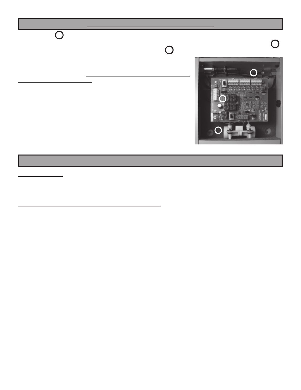
FEATURES
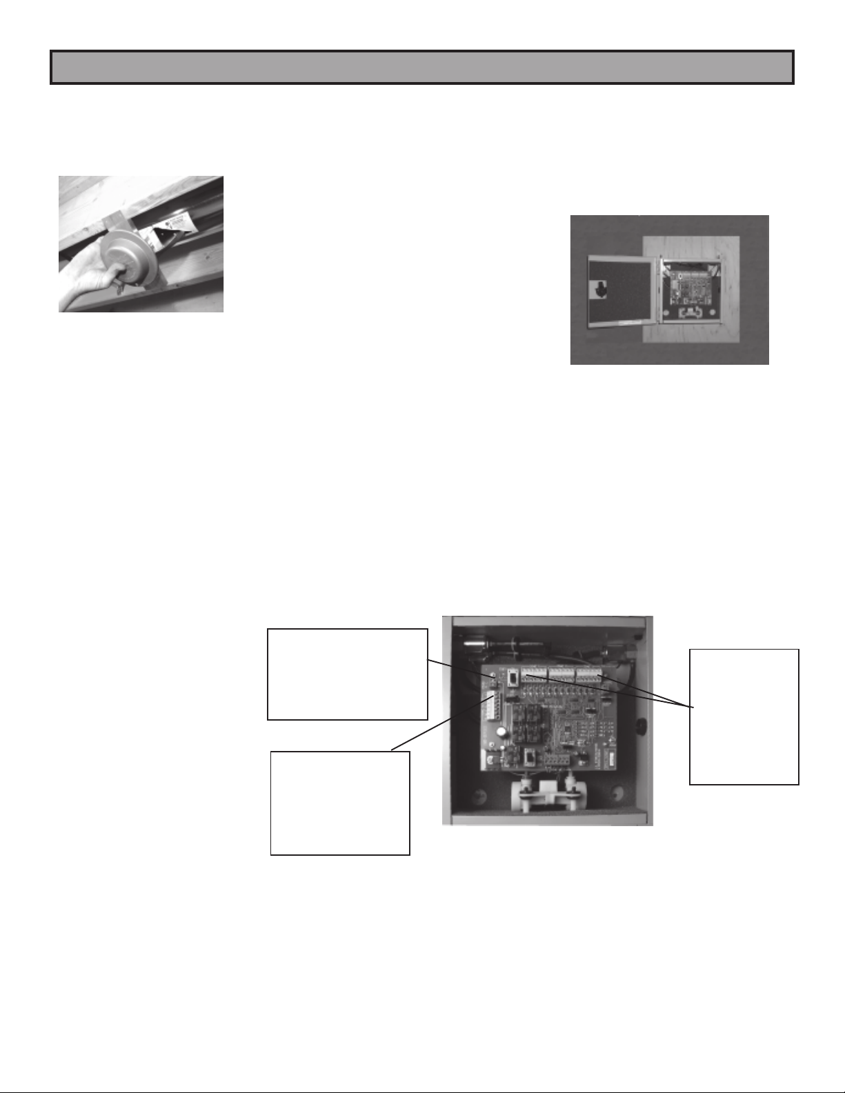
CONTROL PANEL
This Zoning System must be installed by a qualified HVAC Contractor!
Package Contents
1 pc Zonocity™ Series Control Panel (2 or 3 Zone)
1 pc 24VAC self-resetting transformer
1 pc Installation Instructions
WHEN INSTALLING THIS PRODUCT...
1. Read these instructions carefully. Failure to follow
them could damage the Arzel®Zoning System
and/or cause a hazardous condition.
2. Disconnect power supply to the HVAC system and the
Arzel®system before making any wiring
connections to prevent danger, electrical shock, and
equipment damage.
3. The Arzel®System is designed for indoor use only.
4. You must touch a grounded metal object before
handling the Arzel®Control Panel to avoid potential
loss of internal programs, due to electrostatic
discharge.
5. Install in ambient temperature between 40° and 150°F,
in a non-condensing area.
6. Complete the Commissioning Checks (p. 8) after
installation is complete.
7. The Arzel®Zoning System controls the HVAC
equipment via a set of dry-contact relays. Be sure that
this is compatible with the equipment operating
specifications.
8. All wiring must comply with all applicable electrical codes,
ordinances, and regulations.
9. Use properly grounded tools. Wear safety glasses and
gloves when drilling or cutting sheet metal ducts, fiber
glass, or any hard objects.
10. Panel contains both AC and DC Terminals.
See Equipment Notes (pp. 6 and 7) for more details.
11. Leave these instructions with installed system for future
use.
1. The Arzel® Zoning System uses a
self-contained, low-pressure air pump to
actuate dampers.
2. All zones have full-function, single-stage,
heating,cooling, and fan capability from all
thermostats.
3. All Zonocity™ systems are both furnace and
heat pump compatible.
4. Use any standard 24VAC thermostat,
Programmable / Non-programmable,
auto/manual changeover/Wireless.
5. Built-in heating, cooling, fan priority system.
6. Emergency heat changeover (manual switch or
remote outdoor thermostat) for heat pump
balance point changeover from heat pump to
backup heat functions.
7. Compressor timed off control (delay on break).
When the compressor is turned off, it cannot
restart for four (4) minutes. This feature allows
the refrigerant pressure to balance before
restarting.
8. “FAN ON HEAT” switch generates fan call
anytimethere is a call for heat: typically used
with hydronic coils or electric heat.
9. Manual Pump Switch (MPS™) is provided to start
the pump manually and open all the zone dampers.
10. Dampers remain open in the last zone that called
for service to take advantage of additional energy
savings from blower timed-off cycles that exist on
all heating and some cooling equipment.
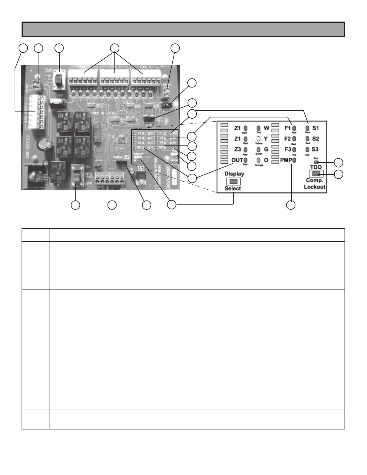
11. LEDs indicate all system operations.
12. A 40VA, 24VAC, self-resetting, plug-in type
transformer is provided to power this Zonocity™
equipment and thermostats.
Caution - Electrical Hazard
Can cause personal injury or equipment damage. Disconnect power to all systems before beginning installation.