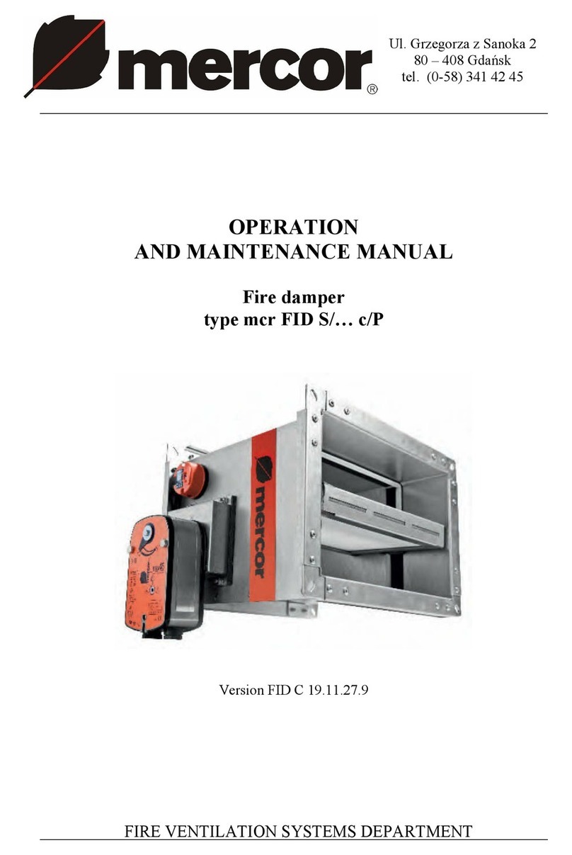
mercor mcr FID S User manual

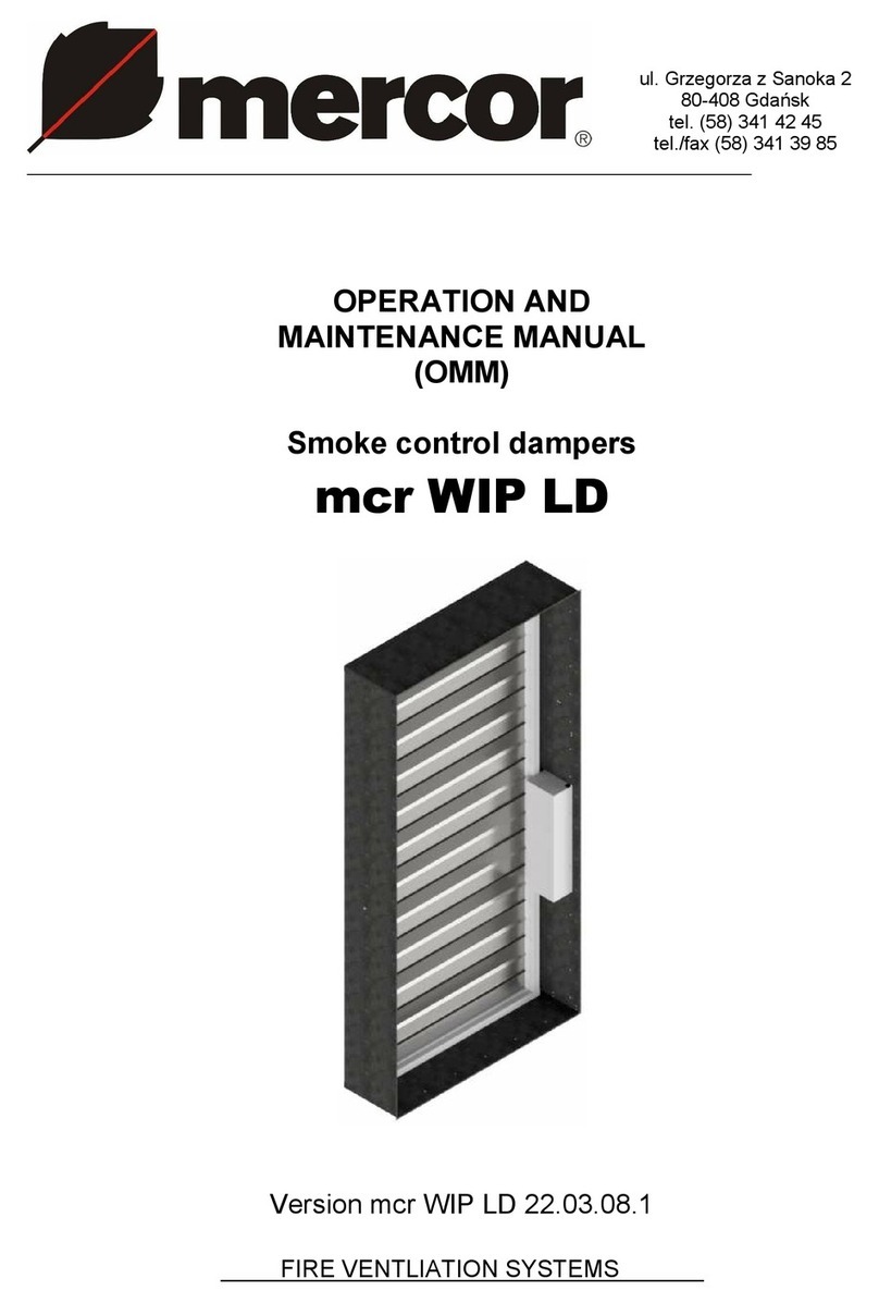
Ul. Grzegorza z Sanoka 2
80-408 Gdańsk
tel. (0-58) 341 42 45
tel./fax +48 58 341 39 85
OPERATION AND
MAINTENANCE MANUAL
(OMM)
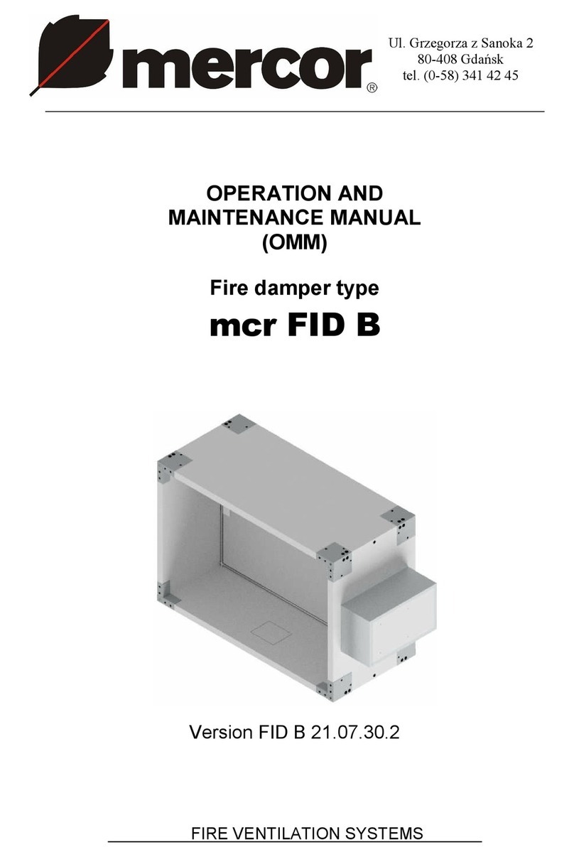
Fire damper type
mcr FID S
Version FID S 22.02.02.18
FIRE VENTILATION SYSTEMS

mcr FID S/... p/...single-plane fire dampers
“MERCOR”SA –The company reserves the right to modify and change the document. Version FID S 22.02.02.18 2/28
TABLE OF CONTENTS:
1. INTRODUCTION ......................................................................................................................................................3
2. SUBJECT..................................................................................................................................................................3
3. DEVICE INTENDED USE.........................................................................................................................................3
4. DESIGN AND OPERATING PRINCIPLE.................................................................................................................4
5. DEVICE IDENTIFICATION.......................................................................................................................................8
6. INSTALLATION ........................................................................................................................................................8
6.1. PRE-ASSEMBLY INSPECTION.....................................................................................................................9
6.2. INSTALLATION OPENING.............................................................................................................................9
6.3. EMBEDDING...................................................................................................................................................9
6.4. ELECTRICAL CONNECTIONS ....................................................................................................................15
7. TRANSPORT & STORAGE CONDITIONS............................................................................................................21
8. MAINTENANCE AND SERVICING........................................................................................................................21
9. WARRANTY TERMS & CONDITIONS ..................................................................................................................21
Technical Manual designations
Option available
Option unavailable
CAUTION
All previous issues of this Technical Manual expire on the date of issue hereof.
The Technical Manual does not apply to the fire dampers manufactured before its date of
issue.

mcr FID S/... p/...single-plane fire dampers
“MERCOR”SA –The company reserves the right to modify and change the document. Version FID S 22.02.02.18 3/28
CAUTION
The product should be stored and used in rooms where:
• there is no access to dust, gases, caustic vapors and other aggressive chemical
vapors that can destroy the insulating elements and structural elements;
• the dampers are not affected by direct sunlight and UV radiation;
• the maximum relative humidity does not exceed 80% at the temperature of +20 ºC;
• the ambient temperature is between - 20 ºC and + 40 ºC;
• there are no vibrations.
In the case of cut-off and transfer fire dampers, the device is equipped with a thermal release containing
one-time temperature fuses. During normal operation, the above mentioned element should be protected
against the affect of the permissible temperature Tmax (see the table below). When it is exceeded, the
temperature fuses may operate, which is a normal operation and is not covered by the guarantee or
warranty.
A thermal release for a damper equipped with an electric actuator:
Thermal fuse for temperature
72 ºC
95 ºC
Temperature fuse inside the duct
Tmax 40 ºC
Tmax 60 ºC
Outdoor temperature fuse
Tmax 40 ºC
Tmax 40 ºC
A thermal release for a damper equipped with KW1 or RST mechanism:
Thermal fuse for temperature
72 ºC
95 ºC
Temperature fuse inside the duct
Tmax 40 ºC
Tmax 60 ºC

mcr FID S/... p/...single-plane fire dampers
“MERCOR”SA –The company reserves the right to modify and change the document. Version FID S 22.02.02.18 4/28
1. INTRODUCTION
The purpose of this operation and maintenance manual is to get the user acquainted with the intended use, design,
the principle of operation, correct installation and operation of the product.
The manual also includes additional information about the operating conditions, maintenance and warranty conditions
of the product.
2. SUBJECT
This manual concerns the entire group of single-plane fire dampers type mcr FID S/... p/... . Compliance with the Manual
guidelines ensures correct functioning of the device in terms of fire protection of rooms as well as safety of the system users.
3. DEVICE INTENDED USE
Application
Single-plane fire dampers type mcr FID S/... p/... (square cross-section) may be used as:
shut-off fire dampers –mcr FID S/S p/P
shut-off fire dampers for fire ventilation systems –mcr FID S/V p/P
shut-off fire dampers for mixed fire ventilation systems –mcr FID S/V-M p/P
transfer dampers –mcr FID S/T p/P
relief dampers –mcr FID S/T p/P
Single-plane fire dampers type mcr FID S/X p/O (circular) may be used as:
shut-off fire dampers –mcr FID S/S p/O
shut-off fire dampers for fire ventilation systems –mcr FID S/V p/O
shut-off fire dampers for mixed fire ventilation systems –mcr FID S/V-M p/O
transfer dampers –mcr FID S/T p/O
relief dampers –mcr FID S/T p/O
Caution:
Shut-off fire dampers for fire ventilation systems the mcr FID S/V p/P and fire dampers for mixed fire ventilation
systems the mcr FID S/V-M p/P, have one declaration of performance in accordance with the requirements of law.
The marker -M and the word "mixed" used in the document are trademarks used by the manufacturer.
The construction and execution of the above dampers is the same regardless of the commercial mark.
The dampers cannot be operated in systems exposed to dust, except for when they are included in a special,
individually developed programme of service and technical inspections.
Fire resistance
The damper type mcr FID S/... p/P has the following fire resistance:
EI60S
/S
/V
/V-M
/T
/G
EI120S
/S
/V
/V-M
/T
/G
EI60
/S
/V
/V-M
/T
/G
EI120
/S
/V
/V-M
/T
/G
E60S
/S
/V
/V-M
/T
/G
E120S
/S
/V
/V-M
/T
/G
E60
/S
/V
/V-M
/T
/G
E120
/S
/V
/V-M
/T
/G
The damper type mcr FID S/... p/O has the following fire resistance:
EI60S
/S
/V
/V-M
/T
/G
EI120S
/S
/V
/V-M
/T
/G
EI60
/S
/V
/V-M
/T
/G
EI120
/S
/V
/V-M
/T
/G
E60S
/S
/V
/V-M
/T
/G
E120S
/S
/V
/V-M
/T
/G
E60
/S
/V
/V-M
/T
/G
E120
/S
/V
/V-M
/T
/G
depending on application, method and place of installation of the damper.
Form versions
The available mcr FID S/... p/... fire damper form versions include:
Rectangular dampers –FID S/... p/P
Rectangular dampers –FID S/... p/P with round connections (diameter range 630 < D < 1000)
Round dampers –FID S/... p/O

mcr FID S/... p/...single-plane fire dampers
“MERCOR”SA –The company reserves the right to modify and change the document. Version FID S 22.02.02.18 5/28
Dimension type series
mcr FID S/... p/P fire dampers are manufactured in the following size ranges:
Width: 200 to 1500 mm
Height: 200 to 1500 mm
Width: 296 to 390 mm
Aside from the standard dimensions, the fire dampers may also be manufactured in intermediate sizes. The damper
casing can be made longer on request. Maximum surface area of type mcr FID S/[S,T,G] p/P dampers: 1.8 m2.
Maximum surface area of type mcr FID S/V p/P dampers: 1.5 m2. Maximum surface area of type mcr FID S/V-M p/P
dampers: 1.25 m2. The minimum damper surface area is 0.04 m2.
The mcr FID S/... p/O fire dampers are manufactured in the following size ranges:
Diameter: 125 to 630 mm
Width: 296 to 390 mm
Aside from the standard dimensions, the fire dampers may also be manufactured in intermediate sizes. The damper
casing can be made longer on request. Maximum surface area of type mcr FID S/… p/O dampers: 0.31 m2. The
minimum damper surface area is 0.01 m2.
The single dampers in multiple fire damper sets mcr FID S/V p/P and mcr FID S/V-M p/P are produced in the following
size ranges:
Width: 200 to 710mm
Height: 200 to 1500mm
Aside from the standard dimensions, the fire dampers may also be manufactured in intermediate sizes. Dampers in
batteries (sets) may only be installed with a vertical axis of rotation. The damper casing can be made longer on
request. The multiple fire dampers sets consists of a minimum of two dampers and a maksimum of three dampers
assembled together connected by the side B . Fire dampers can by only mounted with a vertical axis of rotation.
Release and control mechanisms can be located at the top or bottom of the damper.
4. DESIGN AND OPERATING PRINCIPLE
Design
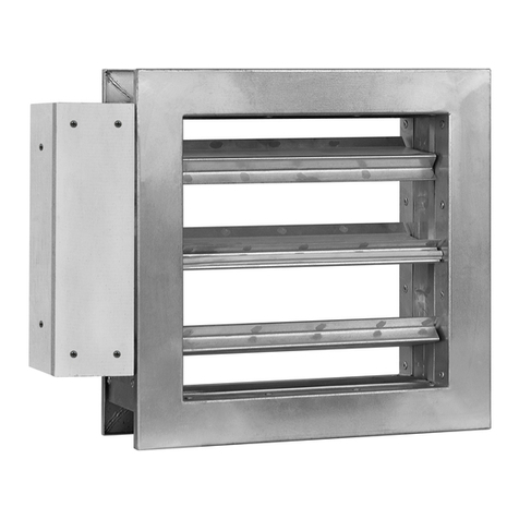
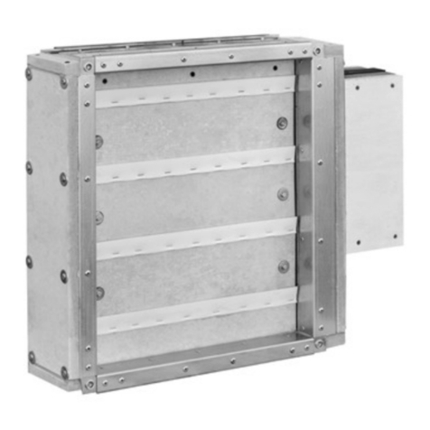
The mcr FID S/… p/… single-plane fire dampers comprise a casing with a rectangular or circular cross-section
(depending on the form version), a moving isolation partition, made of two segments separated by a fire-proof panel,
and a trigger control gear which is tripped remotely or automatically by tripping a thermal trigger. The damper casing
is made of steel sheet, galvanized steel sheet or stainless steel sheet. The isolation partition is made of a fire-proof
panel set in a reinforcement profile made of metal sheet. The inner side of the fire damper casing features a
intumescent gasket. There are stop shapes fastened to the inner casing surface and made of steel, galvanized steel
or stainless steel sheet, which limit the rotating motion of the isolation partition. The stop shapes are lined with a
ventilation-grade seal. The rectangular form version has both ends of the fire damper body with flanged connections,
whereas the circular form version features nipple connections (øD-2). The circular form version can also be
manufactured with flanged ends.
Function
The operating principle and behaviour of the mcr FID S/... p/... single-plane dampers depend on their application
versions:
shut-off fire dampers –mcr FID S/S p/P
In the normal operating position the dampers are open. The dampers are closed (to the safety position) as
follows:
automatically, by tripping the thermoelectric trigger
manually, by pressing the control button on the thermoelectric trigger
remotely, by tripping an electric axial actuator with a return spring caused by isolation from the supply
voltage
automatically, by tripping the thermal trigger and the driving spring
shut-off fire dampers for fire ventilation systems –mcr FID S/V p/P
In the normal operating position the dampers are closed. The dampers are opened (to the safety position) as
follows:
remotely, by tripping an electric axial actuator without a return spring, as a result of applying the supply
voltage to the actuator in the right manner
remotely, by tripping the electromagnetic release and a spring as a result of applying the voltage
shut-off fire dampers for mixed fire ventilation systems –mcr FID S/V-M p/P
In normal operation the dampers are closed or open, depending on the function carried out. The dampers are
opened/closed (to the safety position) as follows:

mcr FID S/... p/...single-plane fire dampers
“MERCOR”SA –The company reserves the right to modify and change the document. Version FID S 22.02.02.18 6/28
remotely, by tripping the electrical axial actuator without a return spring in order to apply supply voltage to
the actuator in the right manner
remotely, by tripping the electromagnetic release and a spring as a result of applying the voltage
transfer fire dampers –mcr FID S/T p/P
In the normal operating position the dampers are open or closed. The dampers are switched to the safety
position as follows:
automatically, by tripping the thermoelectric trigger
manually, by pressing the control button on the thermoelectric trigger
remotely, by tripping an electric axial actuator with a return spring caused by isolation from the supply
voltage
automatically, by tripping the thermal trigger and the driving spring
relief fire dampers –mcr FID S/G p/P
In normal operation the dampers are closed or open, depending on the function carried out. The dampers
are opened/closed (to the safety position) as follows:
remotely, by tripping an electric axial actuator with a return spring caused by isolation from the supply
voltage The actuator has no thermoelectric trigger.
The operating principle and behaviour of the mcr FID S/... p/... single-plane dampers depend on their application
versions:
shut-off fire dampers –mcr FID S/S p/O
In the normal operating position the dampers are open. The dampers are closed (to the safety position) as
follows:
automatically, by tripping the thermoelectric trigger
manually, by pressing the control button on the thermoelectric trigger
remotely, by tripping an electric axial actuator with a return spring caused by isolation from the supply
voltage
automatically, by tripping the thermal trigger and the driving spring
shut-off fire dampers for fire ventilation systems –mcr FID S/V p/O
In the normal operating position the dampers are closed. The dampers are opened (to the safety position) as
follows:
remotely, by tripping an electric axial actuator without a return spring, as a result of applying the supply
voltage to the actuator in the right manner
remotely, by tripping the electromagnetic release and a spring as a result of applying the voltage
shut-off fire dampers for mixed fire ventilation systems –mcr FID S/M p/O
In normal operation the dampers are closed or open, depending on the function carried out. The dampers
are opened/closed (to the safety position) as follows:
remotely, by tripping the electrical axial actuator without a return spring in order to apply supply voltage to
the actuator in the right manner
remotely, by tripping the electromagnetic release and a spring as a result of applying the voltage
transfer fire dampers –mcr FID S/T p/O
In the normal operating position the dampers are open or closed. The dampers are switched to the safety
position as follows:
automatically, by tripping the thermoelectric trigger
manually, by pressing the control button on the thermoelectric trigger
remotely, by tripping an electric axial actuator with a return spring caused by isolation from the supply
voltage
automatically, by tripping the thermal trigger and the driving spring
relief fire dampers –mcr FID S/G p/O
In normal operation the dampers are closed or open, depending on the function carried out. The dampers
are opened/closed (to the safety position) as follows:
remotely, by tripping an electric axial actuator with a return spring caused by isolation from the supply
voltage. The actuator has no thermoelectric trigger.
It is possible to manually service check the proper performance of the dampers with electrical actuators by placing a
special hex wrench in the socket marked on the actuator and rotating it to set the damper isolating partition in the
relevant position. Rotate the wrench slowly, smoothly and carefully. Rotating the wrench too fast or too rapidly may
damage the internal actuator gear or the drive transmission system.
It is possible to manually service check the proper performance of the integrated damper with the trigger control gear
by pressing the lever on the gear.
The mcr T2 tester is recommended to check the proper performance of dampers with electric actuators.
CAUTION
mcr FID S/... p/...single-plane fire dampers
“MERCOR”SA –The company reserves the right to modify and change the document. Version FID S 22.02.02.18 7/28
Never pull directly on the damper isolation partition to open or close the device. This may result in
damage of the self-locking driving gear of the damper that is not covered by warranty. It is
recommended that the fire damper were opened and closed when the ventilation system is turned
off.
Trigger control gears
The following trigger control gears are available for the mcr FID S/… p/… fire dampers:
Electric actuator:
BF 230-T
/S
/V
/V-M
/T
/G
BE 230
/S
/V
/V-M
/T
/G
BF 24-T (-ST)
/S
/V
/V-M
/T
/G
BE 24 (-ST)
/S
/V
/V-M
/T
/G
BF 24-T-TL
/S
/V
/V-M
/T
/G
BLE 230
/S
/V
/V-M
/T
/G
BFL 230-T
/S
/V
/V-M
/T
/G
BLE 24 (-ST)
/S
/V
/V-M
/T
/G
BFL 24-T (-ST)
/S
/V
/V-M
/T
/G
EXBF 230
/S
/V
/V-M
/T
/G
BFN 230-T
/S
/V
/V-M
/T
/G
EXBF 24
/S
/V
/V-M
/T
/G
BFN 24-T (-ST)
/S
/V
/V-M
/T
/G
BF 230-TN
/S
/V
/V-M
/T
/G
BF 24-TN (-ST)
/S
/V
/V-M
/T
/G
BF 24-TN-TL
/S
/V
/V-M
/T
/G
BEE 230
/S
/V
/V-M
/T
/G
BEE 24 (-ST)
/S
/V
/V-M
/T
/G
BEN 230
/S
/V
/V-M
/T
/G
BEN 24 (-ST)
/S
/V
/V-M
/T
/G
MF 230-T
/S
/V
/V-M
/T
/G
MF 24-T
/S
/V
/V-M
/T
/G
MLF 230-T
/S
/V
/V-M
/T
/G
MLF 24-T
/S
/V
/V-M
/T
/G
Spring gear:
RST
/S
/V
/V-M
/T
/G
RST/KW1/S
/S
/V
/V-M
/T
/G
RST/KW1/24P
/S
/V
/V-M
/T
/G
RST/KW1/24I
/S
/V
/V-M
/T
/G
RST/KW1/230P
/S
/V
/V-M
/T
/G
RST/KW1/230I
/S
/V
/V-M
/T
/G
Basic dimensions
Gear
A
C
D
E
BF
198
10
75
70
BFN
157
30
75
62
BFL
138
30
75
58
BF 24TL-ST
198
10
75
70
EXBF
225
55
75
175
* embedding border
mcr FID S/… p/P fire damper with actuator
Gear
A
C
D
E
F
BE
198
10
75
70
345
BLE
157
30
75
62
305
BEE
149
28
75
52
305
BEN
130
20
75
48
305
* embedding border
mcr FID S/… p/P fire damper with actuator

mcr FID S/... p/...single-plane fire dampers
“MERCOR”SA –The company reserves the right to modify and change the document. Version FID S 22.02.02.18 8/28
Gear
A
C
D
E
BF
198
10
75
50
BFN
157
30
75
42
BFL
138
30
75
38
BF 24TL-ST
198
10
75
50
EXBF
225
55
75
160
* embedding border
mcr FID S/… p/O fire damper with actuator
Gear
A
C
D
E
RST
50
30
75
75
* embedding border
mcr FID S/… p/P fire damper with RST
Gear
A
C
D
E
RST
40
30
75
55
* embedding border
mcr FID S/… p/O fire damper with RST
Gear
A
C
D
E
RST/KW1
130
30
75
85
* embedding border
mcr FID S/… p/P fire damper with RST/KW1

mcr FID S/... p/...single-plane fire dampers
“MERCOR”SA –The company reserves the right to modify and change the document. Version FID S 22.02.02.18 9/28
Gear
A
C
D
E
RST/KW1
130
30
75
65
* embedding border
mcr FID S/… p/O fire damper with RST/KW1
5. DEVICE IDENTIFICATION
mcr FID S/... p/P
B x H
/1
/2
/3
6. DEVICE ASSEMBLY
CAUTION
During the assembly of the damper and installation finish, future access to the device and removal
of the trigger control gear must be considered to enable servicing and inspection.
The mcr FID S/... p/P dampers can be installed in the following building partitions (i.e. walls or ceilings):
masonry and concrete walls min. 110 mm thick
masonry walls of bricks or blocks min. 110 mm thick
panel walls min. 125 mm
floor slabs min. 150 mm thick
Additionally, the dampers can be installed:
outside of walls*
in modules (multiple damper sets)**
in batteries (multiple damper sets)***
*available for the mcr FID S/S p/P and mcr FID S/V p/P damper
** available for the, mcr FID S/S p/P the mcr FID S/V p/P and mcr FID S/V-M p/P damper
***available for the mcr FID S/V p/P and mcr FID S/V-M p/P damper
The mcr FID S/... p/O dampers can be installed in the following building partitions (i.e. walls or ceilings):
masonry and concrete walls min. 110 mm thick
masonry walls of bricks or blocks min. 110 mm thick
panel walls min. 125 mm
floor slabs min. 150 mm thick
Additionally, the dampers can be installed:
outside of walls
in modules (multiple damper sets)
The mcr FID S/... p/... fire dampers may also be installed in partitions with a lower class of fire resistance. In this case
the damper fire resistance is equal to the partition fire resistance if the smoke tightness is met. When installing the
Optional fittings
Material
Trigger control gear
Width x height / diameter (nominal)
Damper type

mcr FID S/... p/...single-plane fire dampers
“MERCOR”SA –The company reserves the right to modify and change the document. Version FID S 22.02.02.18 10/28
fire damper in a wall the thickness of which is below the required minimum, increase the thickness at the installation
location e.g. by adding an extra slab or other suitable construction material around the damper circumference.
6.1. PRE-ASSEMBLY INSPECTION
Each fire damper is factory inspected by the manufacturer prior to packing and shipping. Upon unpacking the
delivered fire damper, visually examine it for any damage in transport or casing deformation.
6.2. INSTALLATION OPENING
The minimum dimensions of the installation opening that permits correct installation of the rectangular
damper is (B+90)x(H+90) mm. The minimum dimensionsof the installationopeningfor thecircular damper
is (D+90) mm.
Preparation of the installation opening
6.3. EMBEDDING / FIXING THE DAMPER
Protecting the damper against buckling
The mcr FID S/... p/.. fire damper will work properly if the isolation partition rotation axis is horizontal. If the fire damper
must have the axis in the vertical, state this when ordering. In this case the manufacturer adds optional accessories
with keep clearance between the damper body and the partition at the damper bottom. If the fire damper must be
installed with the rotation axis vertical when the device has already been delivered on site, follow Section 6.5.
The trigger control gear may be located on the right or on the left hand side of the damper at any direction of air flow.
Before embedding/fixing, place the damper axially aligned within the partition (the wall or ceiling which separates the
fire zones) in the finished installation opening. Level the device and secure in place. Next, actuate the damper
isolation partition by hand to verify that the rotation is correct (i.e. there is no collision with the damper casing parts,
etc.). Close the damper isolation partition. Install the bracing as shown in the figure. Carefully fill the gap between
the damper casing and the wall with a proper mortar formula that ensures proper wall and damper fire resistance,
and do not let the mortar get into the damper actuation components (i.e. the trigger control gear, the isolation partition,
gaskets and stops). To do this, the fire damper must be covered with plastic film or other suitable material and remain
so until the embedding and finishing is done. The damper must remain closed until the mortar has cured. Once the
mortar has cured, remove the temporary supports and open and close the fire damper to verify its performance.
When installing the fire damper in a panel wall, fill the space between the damper casing and the wall with mineral
wool certified for A1 fire protection rating; the mineral wool density and thickness must ensure fire resistance no less
than the fire resistance of the wall in which the fire damper is installed. The filled space must additionally be sealed
with a proper mortar or putty that has the fire resistance required for the wall.
WRONG!
Brace with wooden blocks

mcr FID S/... p/...single-plane fire dampers
“MERCOR”SA –The company reserves the right to modify and change the document. Version FID S 22.02.02.18 11/28
In order to ensure the fire resistance of the fire separation element, it is mandatory to keep the embedding envelope
boundary: the damper isolation partition rotation axis must be within the wall envelope.
The embedded fire damper must be coaxially connected to the ventilation duct. Protect the fire damper casing from
damage, and specifically from straining the casing during the installation process. The fire damper cannot bear the
load of the ventilation duct or the ventilation system in which it is installed. Drilling the damper enclosure or driving
screws, bolts or other elements that pierce through the casing to the inside of the damper is prohibited. Once
connected to the ventilation ducts, re-verify the fire damper performance.
During the installation of the mcr FID S/... p/... fire damper mind specifically that the thermal trigger (a fusible element)
must not be damaged or exposed to high temperature (from fire, and welding/soldering equipment), which might
trigger it (it is a single use element and not subject to warranty replacement). Do not expose the intumescent gaskets
installed in the fire damper casing to high temperature. Swollen gaskets make it impossible to close the damper. With
the installation finished, carefully clean the fire damper and make sure that there is no debris which could influence
proper performance of the device.
CAUTION
It is crucial to keep the device embedding envelope so that the trigger control gear is outside of
the wall envelope and easily accessible.
1 –Ventilation duct
2 –Sheet-metal screw, ST4.2x16
3 –mcr FID S/... p/P fire damper,
BxH.
4 –Cement mortar (or other as
suitable)
5 –Masonry wall
6 –Ventilation-grade seal
X –wall thickness
Installation of the mcr FID S/... p/P fire damper in masonry and concrete walls
1 –Ventilation duct
2 –mcr FID S/… p/O fire
damper, ØD
3 –Cement mortar (or other as
suitable)
4 –Masonry wall
X –wall thickness
Installation of the mcr FID S/... p/O fire damper in masonry and concrete walls

mcr FID S/... p/...single-plane fire dampers
“MERCOR”SA –The company reserves the right to modify and change the document. Version FID S 22.02.02.18 12/28
1 –Ventilation duct
2 –Sheet-metal screw,
ST4.2x16
3 –mcr FID S/... p/P fire
damper, BxH.
4 –Cement mortar (or other as
suitable)
5 –Wall of concrete
blocks or solid bricks
6 –Ventilation-grade seal
X –wall thickness
Installation of the mcr FID S/... p/P fire damper in concrete block or solid brick walls
1 –Ventilation duct.
2 –mcr FID S/… p/O fire damper,
ØD
3 –Cement mortar (or other as
suitable)
4 –Wall of concrete blocks
or solid bricks
X –wall thickness
Installation of the mcr FID S/... p/O fire damper in concrete block or solid brick walls

mcr FID S/... p/...single-plane fire dampers
“MERCOR”SA –The company reserves the right to modify and change the document. Version FID S 22.02.02.18 13/28
1 –Ventilation duct
2 –Sheet-metal screw, ST4.2x16
3 –mcr FID S/... p/P fire damper, BxH.
4 –Cement mortar (or other as suitable)
5 –Floor slab
6 –High temperature gasket
7 –Installation profile
8 –Steel expanded plug
M8 metal screw
X –wall thickness
Installation of the mcr FID S/... p/P fire damper in a floor slab, cont'd
Steel expanded plug
hole

mcr FID S/... p/...single-plane fire dampers
“MERCOR”SA –The company reserves the right to modify and change the document. Version FID S 22.02.02.18 14/28
1 –Ventilation duct.
2 –mcr FID S/… p/O fire
damper, ØD
3 –Cement mortar (or other as
suitable)
4 –Floor slab
X –wall thickness
Installation of the mcr FID S/... p/O fire damper in a floor slab
1 –Ventilation duct.
2 –Sheet-metal screw, ST4.2x16
3 –mcr FID S/... p/P fire damper, BxH.
4 –Cement mortar (or other as suitable)
5 –Mineral wool, min. density = 80 kg/m3.
6 –High temperature gasket
7 –Panel wall
8 –Screw, ST5.5x35
9 –Structural profile
X –wall thickness
Installation of the mcr FID S/... p/P fire damper in a panel wall

mcr FID S/... p/...single-plane fire dampers
“MERCOR”SA –The company reserves the right to modify and change the document. Version FID S 22.02.02.18 15/28
1 –Ventilation duct.
2 –mcr FID S/… p/O fire damper, ØD
3 –E.g. cement mortar.
4 –Panel wall
5 –Mineral wool, min. density = 80 kg/m3.
6 –Structural profile
7 –Screw, ST5.5x35
X –wall thickness
Installation of the mcr FID S/... p/O fire damper in a panel wall
1 –mcr FID S/... p/P fire damper, BxH.
2 –Threaded rod
3 -Fire protective board that provides fire
resistance in class EIS 120
4 –solid wall
5 –masonry mortar (or other as suitable)
6 –Fire protective band
Installation of the mcr FID S/... p/P outside of walls

mcr FID S/... p/...single-plane fire dampers
“MERCOR”SA –The company reserves the right to modify and change the document. Version FID S 22.02.02.18 16/28
1 –mcr FID S/V p/P BxH damper
4 –M8 dowel
7 –Building partition
2 –Cover grille with ventilation duct
5 –Frame from fireproof board 20mm thick
8 –Smoke extraction duct*
3 –M10 fixing screw
6 –Eg gypsum mortar
9 -Suspension system
Installation of the mcr FID S/V p/P damper in fire ventilation systems (building partitions / horizontal
fire ventilation ducts)
1 –mcr FID S/V p/P BxH damper
4 –M8 dowel
7 –Building partition
2 –Cover grille
5 –Frame from fireproof board 20mm thick
8 –Smoke extraction duct*
3 –M10 fixing screw
6 –Eg gypsum mortar
Installation of the mcr FID S/V p/P damper in fire ventilation systems (building shafts for fire
ventilation)

mcr FID S/... p/...single-plane fire dampers
“MERCOR”SA –The company reserves the right to modify and change the document. Version FID S 22.02.02.18 17/28
1 –Floor slab
2 –Smoke extraction duct*
3 –Eg gypsum mortar
4 –mcr FID S/V p/P BxH damper
5 - Cover grille with ventilation duct
Installation of the mcr FID S / V p / P damper in fire ventilation systems (building partitions /
vertical fire ventilation ducts)
CAUTION
* Smoke extraction duct should be made in accordance with the duct manufacturer's guidelines. The ducts must have
adequate fire resistance in accordance with the fire resistance provided for the entire solution. Seal all connections
between the damper and the ducts with appropriate mortar / glue / gaskets, ensuring fire resistance. The shut-off
damper in vertical position fire ventilation systems may be mounted across the horizontal smoke extract duct or on
the sides of the horizontal smoke extract duct or on the surface of any side of the vertical smoke extract duct.
1 –e.g. a masonry wall
2 –A building element with fire resistance equal or higher
to the building envelope resistance
3 –mcr FID S/... p/P fire damper, BxH.
4 –A building element with fire resistance equal or higher to
the building envelope resistance. For example, a brick wall.
5 –e.g. mortar
Installation of the mcr FID S/... p/P fire damper as a module (multiple damper set of 4 dampers)
Other configurations of the mcr FID S /... p/P dampers modules can be made, consisting of two or more dampers, while
maintaining the minimum distances between the dampers according to the drawing above

mcr FID S/... p/...single-plane fire dampers
“MERCOR”SA –The company reserves the right to modify and change the document. Version FID S 22.02.02.18 18/28
1 –e.g. a masonry wall
2 –mcr FID S/V p/P or mcr FID S/V-M BxH.
3 –fire protective band from from GKF boards, width
min. 50mm
4 –mineral wool with density min. 100kg/m3
5 –angle U50, thickness 2mm, fastened with St4,6 screws,
alternating every 100mm
6 –e.g. mortar
Installation of the FID S/V p/P or mcr FID S/V-M p/P fire damper in batteries consisting 3 single
dampers.
Seal the connections with fireproof silicone. Other configurations of mcr FID S/V p/P and mcr FID S/V-M p/P fire
dampers sets can be made, consisting of two or three dampers, while maintaining assembly rules acc. Drawing
above. Installation of control and release mechanisms from the bottom or from the top of damper.
1 –e.g. a masonry wall
2 –mcr FID S/V p/P or mcr FID S/V-M BxH.
3 –Fire protective band from from GKF boards,
width min. 50mm
5 –angle U50, thickness 2mm, fastened with St4,6 screws,
alternating every 100mm
7 - a building element with fire resistance equal or higher to the
building envelope resistance
Modular installation of the mcr FID S/V p/P or mcr FID S/V-M p/P fire damper in 4 batteries
(multiple damper set)

mcr FID S/... p/...single-plane fire dampers
“MERCOR”SA –The company reserves the right to modify and change the document. Version FID S 22.02.02.18 19/28
Seal the connections with fireproof silicone. Other configurations of mcr FID S/V p/P and mcr FID S/V-M p/P fire
dampers sets can be made, consisting of two or three dampers, while maintaining assembly rules acc. drawing
above. Keep a distance of 10mm between the individual batteries of the damper. Batteries can be vertically and
horizontally next to each other. Installation of control and release mechanisms from the bottom or from the top of
damper.
1 –e.g. a masonry wall
2 –damper mcr FID S/S p/P BxH.
3 –fire protective band from from GKF
boards, width min. 50mm
Modular installation of the mcr FID S/S p/P damper consisting of two or more dampers
Configurations consisting of two or more mcr FID S/S p/P fire dampers with maximum dimensions of a single fire damper
BxH: 1500x1105 mm are allowed, while maintaining the installation rules according to the figure above. L = 60 ÷200mm.
Installation of power and control mechanisms from the bottom or top of the damper. Joints should be sealed with fire-
retardant silicone.
1 –e.g. a masonry wall
2 –damper mcr FID S/S p/P BxH.
3 –fire protective band from from GKF
boards, width min. 50mm
Modular installation of the mcr FID S/S p/P damper consisting of two or more dampers

mcr FID S/... p/...single-plane fire dampers
“MERCOR”SA –The company reserves the right to modify and change the document. Version FID S 22.02.02.18 20/28
Configurations consisting of two or more mcr FID S/S p/P fire dampers with maximum dimensions of a single fire damper
BxH: 1500x1105 mm are allowed, while maintaining the installation rules according to the figure above. Installation of
power and controlmechanismsfrom the bottom or top of the damper. Joints should be sealed with fire-retardant silicone.
6.4. ELECTRICAL CONNECTIONS
With the fire damper properly installed and embedded connect the electrical system wiring to the fire damper, if the
device features controls or other parts that require electric power supply. The following shows the connection
diagrams and basic electrical data for the trigger control gears supplied with the mcr FID S/... p/... fire dampers.
Electric actuators –electrical specification
Actuator type
Location of the damper isolation partition
- Belimo BFL series
- Belimo BFN series
- Belimo BF series
- Mercor MLF series
- Mercor MF series
Open isolation partition –actuator indication: 90
Closed isolation partition –actuator indication: 0
- Belimo serii BE
- Belimo serii BLE
- Belimo serii BEE
- Belimo serii BEN
Open isolation partition –actuator indication: 0
Closed isolation partition –actuator indication: 90
Technical specifications
BF 24, BF24-T, BF24-TN, MF 24T
BF230, BF230-T, BF230-TN, MF 230T
Power supply
AC 24V 50/60Hz DC 24V
AC 220-240V 50/60 Hz
Power demand:
- for spring tensioning
- for spring holding
7 W
2 W
8,5 W
3 W
Sizing (apparent power)
10 VA
11 VA
Appliance class
III
II
Ingress protection rating
IP 54
IP 54
Auxiliary circuit breaker:
2xSPDT
6 (3) A, 250V
2xSPDT
3 A, 250V~
- activation position [degrees]
5°, 80°
5°, 80°
Torque:
- motor
18 Nm
18 Nm
- spring
12 Nm
12 Nm
Cable connection:
- motor (L = 0.9 m)
2x0,75 mm2
2x0,75 mm2
- auxiliary circuit breaker
6x0,75 mm2
6x0,75 mm2
Movement time: (0-90°)
- motor
120 s
120 s
- return spring
16 s
16 s
Operating temperature range
- 30 ...+50°C
- 30 ...+50°C
Sound pressure level:
- motor
max 45 dB (A)
max 45 dB (A)
- spring
~ 63 dB (A)
~ 63 dB (A)
Technical specifications
BE24, BE24-ST
BE230
BLE24, BLE24-ST
BLE230
Power supply
AC 24V 50/60Hz
DC 24 V
AC 220-240V 50/60 Hz
AC 24V 50/60Hz
DC 24V
AC 220-240V 50/60 Hz
Power demand:
- for spring tensioning
12 W
8 W
7.5 W
5 W
- for spring holding
0,5W
0,5 W
0,5 W
1 W
Sizing (apparent power)
18 VA
15 VA
9 VA
12 VA
Appliance class
III
II
III
II
Ingress protection rating
IP 54
IP 54
IP 54
IP 54
Auxiliary circuit breaker:
2xSPDT
6(3) A, 250V
2xSPDT
6(3) A, 250V
2xSPDT
3A, AC 250V
2xSPDT
3A, AC 250V
- activation position [degrees]
3°, 87°
3°, 87°
3°, 87°
3°, 87°
Torque:
- motor
40 Nm
40 Nm
15 Nm
15 Nm
- locking
50 Nm
50 Nm
20 Nm
20 Nm
Cable connection:
- motor (L = 0.9 m)
3x0,75 mm2
3x0,75 mm2
3x0,75 mm2
3x0,75 mm2
- auxiliary circuit breaker
6x0,75 mm2
6x0,75 mm2
6x0,75 mm2
6x0,75 mm2
Movement time: (0-90°)
60s
60 s
30 s
30 s
- motor
Operating temperature range
- 30 ...+50°C
- 30 ...+50°C
- 30 ...+50°C
- 30 ...+50°C
Sound pressure level:
- motor
max 62 dB (A)
max 62 dB (A)
max 62 dB (A)
max 62 dB (A)
Table of contents
Other mercor Fire And Smoke Damper manuals

mercor
mercor mcr FID PRO Series User manual

mercor
mercor mcr DOR User manual

mercor
mercor mcr LAM User manual

mercor
mercor mcr FID 240 User manual

mercor
mercor mcr ZIPP User manual

mercor
mercor mcr WIP LD User manual

mercor
mercor mcr PL1 Operator's manual

mercor
mercor mcr WIP EI60S User manual

mercor
mercor mcr Prosmoke FS User manual

mercor
mercor mcr WIP PRO Series User manual
Popular Fire And Smoke Damper manuals by other brands

SMAY
SMAY WKP-P installation manual

Arzel
Arzel Heat PumPro Installation & operation instructions

AEROPRODUKT
AEROPRODUKT BSK-J/EI90 manual

Ace
Ace FDT Operating and mounting instructions

ATI Technologies
ATI Technologies LS1 Installation instruction

LUCOMA
LUCOMA RGK-10 Series Installation, operation and maintenance instructions