SIOX TELEFRANG R40 Series User manual

TELEFRANG AB
SIOX Modem Expander R40
General Description
R40 is an interface unit be-
tween a GSM modem and
several serial devices using
RS232, RS485 and a SIOX
bus. It is powered from mains
or a DC supply, 10..48 V.
In addition, it includes 2 ana-
log inputs which also may be
used for alarms etc. Its en-
hanced PLC programmability
permits it to work standalone,
as a protocol converter or as
the multiplexer for a modem.
Versions: R40-3, 12V powered SIOX Modem Expander.
Order number: 6R40-3
R40-4, Mains powered SIOX Modem Expander.
Order number: 6R40-4
R40-5, 24V powered SIOX Modem Expander with power Relay.
Order number: 6R40-5
R40man.wpd/090513/TF
R40 MODEM EXPANDER MODULE p 2
Contents
General Description .......................................1
Versions .................................................1
Power Supply ............................................3
Installation and Start-Up ...................................3
Terminal Blocks ..........................................4
SIOX Address Setup .......................................5
RS485 Soft Handshaking ...................................5
Ports’ Multiplexing ........................................6
Modem ..................................................7
Modem-to-SIOX LINK Mode .................................7
Modem-to-Serial LINK Mode ................................8
SIOX Text-to-Serial LINK Mode ..............................8
PLC .....................................................8
Digital/Analog Inputs ......................................9
Power Relay .............................................9
SIOX Message Transfer for R40 .............................9
Parameter Setup .........................................11
Safety Precautions .......................................17
Electrical Specifications ..................................18
Environmental Specifications ..............................18
Mechanical Specifications .................................18
R40 MODEM EXPANDER MODULE p 3
Power Supply
All R40 versions may be powered from a 10 - 50 V DC supply, nominally 24 V,
delivering minimum 4 W. An internal switching regulator consumes less current
when the voltage increases. An extra 1 W is required if the SIOX bus is supp-
lied from the unit via the jumpers on the left side. The relay in R40-5 requires
minimum a 20V supply to operate.
The R40-4 version can alternatively be supplied with 230 V AC via the two
terminals marked 230 VAC on the printed circuit board. A 63 mA, Time Lag
(Anti Surge), HRC (High Rupture Capacity) fuse protects the circuit. For fixed
installation, an external 2-pole mains switch must be provided externally.
The transformer has two separate secondaries. The rectified output from the
first operates in parallel with the ordinary DC supply. The other supplies up to
20 mA of current to the SIOX bus, which thus can be fully isolated from the rest
of the module. It may also supply max 50 mA to external devices. In this case,
the load is connected in parallel with the jumper pins from “24V” to “Sx”.
Installation and Start-Up
The R40 is typically wall mounted using the four corner holes. This mounting
does not affect the IP 65 case sealing. Cables must be entered via cable
glands which are adequately tightened to prohibit the cords from being pushed
into/pulled out of the unit. The unit is a Class II equipment intended for
Installation Category II. Please follow the instructions described under “Safety
Precautions” on page 17.
Typically, a two-wire, low capacitance twisted pair is used for the SIOX com-
munication bus. Shielded cables may be used, but unless a correct strategy for
shield grounding is adopted, they may prove to be of little benefit. The total
resistance of the bus must be low, typically below 2 * 50 Ω. Note, that this SIOX
connection must be polarised correctly, or the bus will be short-circuited.
A mains supplied R40 always generates a moderate SIOX bus current. In order
to allow isolation between the bus and the R40 when using a DC supply, the
bus current is generated only if two connecting jumpers are installed from “24V”
to “Sx”. The SIOX bus will then output up to 20mA at 17 - 30 V for DC supplies
from 10 - 50 V.
Polarity of the bus is normally not important since most connected slave
modules don’t care. When used together with e.g. a K32, polarity of the bus
wires must be observed, since both R40 and K32 have their bus minus wired
to the negative supply. If the polarity is wrong, the two units will short out one
another. The K32 should, in most cases, be jumpered to generate 0 mA.
R40 MODEM EXPANDER MODULE p 4
A green LED marked “X” indicates when there is voltage on the SIOX bus.
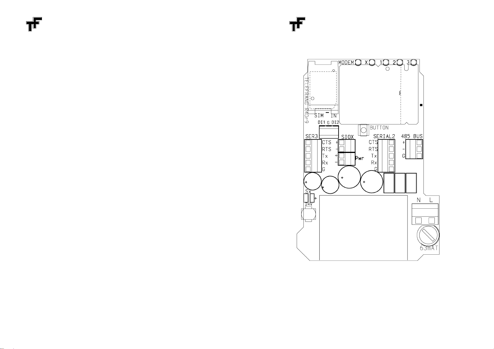
Terminal Blocks
When a proper supply and the SIOX bus have been connected, the com-
munication can be tested and operating modes and application PLC program
entered. Unless otherwise requested, the module is preset at the factory to
communicate as a slave at 4800 bits/s using address 01. General principles for
the SIOX bus and communications are described in a separate manual, the
"SIOX System Description". Changes in operation modes are brought about by
Parameter Setup Strings communicated over the SIOX bus, see page 9.

R40 MODEM EXPANDER MODULE p 5
SIOX Address Setup
When using the SIOX bus, the R40 can be used as a Master, calling other units
on the SIOX bus, or as a Slave, capable of setting up or answering to a GSM
call and linking to the bus after connection. As a Slave, R40 must have a
specified address, which is set in the internal EEPROM in the module. Slave
mode is also used for setting up the module for a specific application. At
delivery, the address is set to 01. It is best changed by connecting the R40 to
a SIOX bus and using the R40SETUP.dff program. This is loaded from the
www.siox.com. The same program allows all other relevant settings.
A special feature is added to help recover "lost" modules, i.e. when an
unknown bit rate and/or address is selected or the PLC runs a program that
erroneously alters parameters affecting the communication. To recover such
a module, a pushbutton is available on the PCB. Carry out the following steps:
1. Press the button close to the modem and apply power. The module will now
communicate at 4800 bits/s using address 63 with the PLC, Links and any
options disabled.
2. Check and reconfigure the EEPROM of the module for proper operation.
3. Restart the module without pressing the button.
RS485 Communication
R40 features one two-wire RS485 port available at a 3-pole screw terminal in
the module. The port is opto isolated from the rest of the module, and the third
terminal is intended for the cable screen. The R40 includes a 220 Ωtermination
resistor and and two 5 kΩto float an unconnected bus to an idle (1) state.
This serial port, as well as the other two below, permit asynchronous communi-
cations at 2400 to 19200 bps using 7 or 8 data bits, even/odd/no parity bit and
one or two stop bits. 19200 bps may generate problems due to the limited
length of the internal buffers and is not recommended. The format is set in
parameter 0/5 (and 0/6/0/7for the RS232 ports), as described in page 13. To
permit handling in a similar way as the RS232 ports, a virtual CTS signal is
provided for this port in the same parameter.
RS485 Soft Handshaking
To stop the receive buffer or the device at the other end of the RS485 bus from
overrunning, special characters in the text can be reserved for Soft Hand-
shaking, often the two ASCII characters DC1 and DC3, called X-ON and X-
OFF. The RS485 port handles this protocol if the reserved characters are set
in parameter 0/3.0/0/0/0/ means no soft handshaking. When the port or the device
R40 MODEM EXPANDER MODULE p 6
face an overrun risk, an X-OFF character is sent. This is not buffered. When
more space is available, an X-ON is sent. Correspondingly, R40 will stop trans-
mitting if the X-OFF character is received and start again at an X-ON.
RS232 Communication
R40 features two standard RS232 ports for connection to a PC, a printer or
similar via one of the 5-pole screw terminals in the module. The ports are indi-
vidually opto isolated from the rest of the module. The signals are described
with R40 used as a DCE, ready for connection to a PC. Typical interface cables
are shown below:
Terminal Function 9p socket 25p plug
to a PC to a modem
Signal Ground 5 7
RD Transmit from R40 2 2 (TD)
TD Receive to R40 3 3 (RD)
CTS Output from R40 (=buffer free) 8 4 (RTS)
RTS Input to R40, with 10 kΩpullup 7 5 (CTS)
RTS and CTS are used for hardware handshaking and can be checked in par-
ameters 0/6 and 0/ 7. The bit rate, parity and number of data and stop bits can
be set up in here too, see page 13.
Ports’ Multiplexing
Characters received from either port are stored in a 128 character ring buffer,
where they can be linked to the modem or fetched, either automatically by the
firmware in R40 or by an application specific PLC program. Correspondingly
there exists a 128 character buffer which empties into the transmit pin. This
buffer is filled by a link from the modem, firmware or by a PLC program.
Since the three possible serial ports use the same buffers, messages must use
the intended serial port. For this purpose, the first port to send a character to
the receive buffer will deactivate the CTS lines of the other two, preventing
them from transmitting. The yellow LED for the receiving port will light. Any data
intended for the ports is transmitted on the active port.
20 seconds after last character in either direction, the priority is cleared and all
channels are allowed to communicate. A PLC program in R40 can reactivate
the CTS lines in advance if necessary.
When text is stored in the transmit buffer without any recent priority, two bits in
parameter 0/4 are checked to define 1, 2 or 3 as the preferred port to send the
message. When such a message is received from the modem, it can be

R40 MODEM EXPANDER MODULE p 7
preceded by a Receive Code, namely the letters “SIOX” and a digit from 1 to
3. This automatically selects the corresponding port number. Other trailing
digits are stored in parameter 10/ to let the PLC read it for other special
conditions. Refer to page 8, PLC.
Modem
The R40-3 includes a GSM/GPRS wireless modem of the type Siemens TC65.
Depending on the version, it uses either an internal antenna or an SMA con-
nector for an external GSM antenna of any standard type. The R45 board
includes a SIM card holder. Press gently on the top surface of the holder and
push upwards. The top flap can now be raised and a SIM card be inserted.
Make sure that the diagonal edge of the card is in the lower right corner of the
holder. Press again on the surface and push down to lock the card.
The modem communicates at 9600 bps with the R40 via one transmit and one
receive buffer, each 128 bytes. These same buffers are also used for Text calls
over the SIOX bus in R40. In this way, an external station on the SIOX bus can
send texts to the TC65 modem and collect answers from the modem. If not
applicable, Text calls to the R40 should be avoided. Normal Data Mode and
Setup Mode calls will not interfere with the buffers. There is also a link mode
where Text Mode talks directly with either serial port without colliding with the
modem buffers.
The two buffers can also be handled by a PLC application in the R40. “DX”
instructions transfer EEPROM or RAM via the output buffer to the modem, and
“KX” instructions fetch text from the modem via the input buffer. So, for
example, an initialising message can be sent to the modem, a call identified
and one of the ports subsequently linked to the modem. Note that the “S” flag
in the accumulator parameter hex 13 must be off during these operations,
otherwise the PLC text instructions will operate on the serial receive/transmit
buffers.
In order to avoid any lock-ups, either connected or in stand-by, the Modem is
automatically restarted after 18 hours and the signal strength and connection
are re-arbitrated. The result, available in parameter 21, is also rechecked after
a finished call. If not desired, the 18h timer can be repeatedly set in parameter
20/ to above 0/0/24 for eternal operation.
Modem-to-SIOX LINK Mode
One standard firmware function in R40 is a LINK mode, where all characters
received from the GSM modem are copied to the SIOX bus, independent of the
bit rates and format. All characters received on the SIOX bus are copied to the
R40 MODEM EXPANDER MODULE p 8
modem. Hereby, a PC with a modem can make direct contact with the SIOX
bus. The SIOX communication firmware operates as usual, but with 1 character
delay in either message direction.
This LINK mode is enabled by setting xx8x in parameter 0/ 4, see page 12. For
extended buses with multiple SIOX nets chained via modem links, only the first
SIOX bus can be allowed to echo characters from TD via SIOX back to RD. In
the other positions, parameter 0/4 should be set to xxAx, which cancels the
echo without disturbing characters originating from modules on the SIOX bus.
After a disconnect of a call, this Link as well as the two below and the preferred
port number stored in the second half of parameter 0/4, are reloaded from
EEPROM to restore the original settings for next call.
Modem-to-Serial LINK Mode
Another LINK flag connects the serial buffers with the modem buffers. In-
dependent of the serial speed and format, the combination buffers 256 bytes
in either direction without changing the contents. This link is enabled by setting
xx4x in parameter 0/4, see page 12.
SIOX Text-to-Serial LINK Mode
A third LINK flag lets SIOX Text messages operate directly on the buffers for
the serial ports in order to output or receive texts from a SIOX external master
to the selected serial port. The Modem is then not disturbed. Setup messages
are not affected. This link is enabled by setting xx2x in parameter 0/4, see page
12.
PLC
R40 includes PLC programmability, which can be used for accessing modules
on the SIOX bus, communicating with the serial ports, communicating with the
modem and setting up connections. It has full control over the Links and other
controlling flags such as the three serial CTS flags to redirect serial output.
The “DX” instructions permit characters, values and text strings, fetched from
either RAM or EEPROM to be transmitted, in most cases to the modem or the
connected remote station. An “S” flag in parameter hex 13 permits redirecting
the text to the current serial port, using their serial buffer.
“KX” and “KCASE” fetch single characters from the receive buffer of the modem

R40 MODEM EXPANDER MODULE p 9
to identify particular parts of the incoming messages. As above, the “S” flag
redirects the fetch to the serial buffer.
In order to identify a typical start sentinel from a serial port or the modem, a
more efficient option is available in the firmware. When the modem signals a
new call via a Data Carrier Detect, during 20 seconds, R40 looks for the fixed
code “SIOX” and a digit from 0 to 3 to select the corresponding port. If found,
a virtual output Q1 is cleared and an input I1 is activated in parameter 10/. The
PLC may also set Q1 to repeat the detection at any time. The trailing character
is saved in parameter 25 and other values than 0 to 3 may be used by the PLC
to trigger other actions.
In the other direction a similar check can be activated. If the virtual output Q2
is set and the receive buffer from the current Serial port collects a 1 - 4 letter
code defined in parameter 22-23 plus an arbitrary character, this character will
be saved in parameter 24. The Input I2 is set and Q2 is cleared. The PLC can
collect the arbitrary character and dial up a remote station or any other action.
Digital/Analog Inputs
Two external inputs are available on a terminal block marked DI1-G-DI2. Their
(inverted) digital status can be checked by the PLC as I6/I7 or read in
parameter 10/ and their analog values in parameter 39 as 00..FF for 0..10 VDC.
Normally they are equipped with 10 kΩpull-ups to +4 V to permit digital
activation when the input is connected to “G”.
Via an option pulses on I6 can be counted in an otherwise free parameter.
Refer to pages 12 and 15.
The “default” Button, described in page 5, is normally readable as I5.
Power Relay
R40-5 includes a power relay, able to switch 8 A at 230VAC. The contact
closure is connected to the screw terminals at the right bottom corner and is
protected by a Time Lag (Anti Surge), HRC (High Rupture Capacity) fuse.
Note that the supply voltage must be above 20 V for the relay to pull. Higher
voltages are regulated to prevent excessive heat in the relay.
SIOX Message Transfer for R40
R40 MODEM EXPANDER MODULE p 10
For details about the communication types it is recommended to read the
"SIOX System Description".
A Data Mode Communication is only used for compatibility with older SIOX
systems and contains status information.
Example single data communication when R40's address is 0/9:
From central (hex notation): C9 0/0/
Address 9
Answer from R40: 0/1 0/3
Status read
String Setup Mode Communications use the same address as Data Mode but
permit a broader scope of information. Any 16-bit parameter value in the
module may be read or written with a choice of RAM or EEPROM. In this case,
the message must contain a parameter number. A typical communication for
reading the digital inputs, parameter 0/9, in String Mode will be:
From central: C0/ 0/9 31 30/BE4F
Address 9 | read 10/ | Sign-off/Checksum
Answer from R40: 30/30/3130/BE 70/
0/ 0/ 1 0/ | Sign-off/Checksum
I5 is active
To permanently change a serial bit rate to 9600, a write data = 0/0/0/9 to
EEPROM parameter number 0/4 (or 0/5) must be done:
From central:
C0/ 0/9 43 34 30/30/30/39BF77
Address 9 | C 4 | 0/0/ 0/ 9 | Sign-off/Chksm
EEPROM write Value 0/0/0/ 9 (hex)
Answer from R40: 30/30/30/39BF 77
0/ 0/ 0/ 9 | Sign-off/Checksum
Value 0/0/0/9 (hex)
String Text Mode Communications are similar to Setup Mode but can handle
an arbitrary text of max 80 characters in either direction. They are distinguished
by hex 40/ being added to the second character in the message address. The
texts use the same buffers as the Modem and should therefore not be used
when a link from the Modem is enabled. When the link SioxText-to-Serial is
activated, the texts are transferred directly via the serial buffers and do not
affect the modem operations.

R40 MODEM EXPANDER MODULE p 11
Parameter Setup
The R40 contains two types of memory: RAM for temporary storage for as long
as the module is connected to a power supply, and EEPROM for long-term
storage of working modes, parameters and initialization values after a power
disconnect. At power-up, the EEPROM variables are automatically copied to
the RAM, and the information is used to control the module. All EEPROM setup
values may be copied again if data = FFFF is written to the first parameter
(number 0/0/ ). This initiates a full soft reset, using previous EEPROM value for
this parameter.
By using String Mode commands, any variable may be read or modified at any
time, either temporarily in RAM or permanently in EEPROM. In the latter case,
the corresponding RAM cell is modified as well. Information in controlling
parameters immediately affect the function of the module.
Below follows a description of each parameter number. All parameter values
are shown in hexadecimal notation.
Pos. Value Function
hex hex
0/0/ FFFF Soft Reset copies EEPROM to RAM.
8xxx Permit Write to all reserved RAM cells.
4xxx Inhibit String Text Mode, where the PLC can submit text answers
which otherwise might empty the Modem Receive Buffer.
x3xx- SIOX Transmission Speed 3 - 9 = 300 - 19200 bits/s.
-x9xx Other values are invalid and revert to 4800 bits/s. To change, a
write to EEPROM must be made, followed by a power-
down/power-up or a Soft Reset.
xx0/ 1-xx3F Group Address if parameter 0/2 is set to x8xx.
0/10/1xx-3Fxx Module Address (1 - 63), EEPROM or temporary value
8xxx Master Flag is set by the PLC program when the R40 is to start
communications over the SIOX bus on its own.
xx8x Inhibit Spy permitting PLC use of Par. 4 /0 - 4F.
R40 MODEM EXPANDER MODULE p 12
Pos. Value Function
hex hex
0/1 xx2x Allow Serial Errors Is useful when the format of the serial port is
uncertain. Received characters with incorrect parity or number
of bits will then be buffered instead of just being scrapped.
xx1x Compress multiple equal text characters in SIOX String Mode
answers. Received compressed texts can always be resolved.
Compressed texts cannot be interpreted by the modem.
0/2 0/0/0/0/ Options reserved for customer specific functions.
x8xx enables Group addresses in parameter 0/0/.
xx1x enables I5 pulse counting in parameter 25.
0/3 XXYY X-ON / X-OFF Characters for software handshaking on RS485.
Typically 1113 (or 0/0/0/0/ if no handshaking).
0/4 8xxx Modem Reset can restart the modem before the default 18
houirs defined in parameter 20/.
4xxx Data Carrier Detect is submitted by the modem when connection
is established over the GSM net.
2xxx Request To Send submitted by the modem when it can collect
buffered characters.
1xxx Clear To Send signals to the modem that the buffer is available.
x8xx Flush Modem Receive Buffer The flag clears automatically.
x4xx Flush Modem Transmit Buffer The flag clears automatically.
x2xx Flush Serial Receive Buffer The flag clears automatically.
x1xx Flush Serial Transmit Buffer The flag clears automatically.
xx8x SIOX Link to Modem of all messages on the SIOX bus.
xxAx Link, No Echo. When SIOX Link is active, characters received
from the modem and transmitted on the SIOX bus will not be
echoed back to the modem again.

R40 MODEM EXPANDER MODULE p 13
Pos. Value Function
hex hex
0/4 xx4x Serial Link to Modem between current serial port and modem.
xx2x SIOX Text Link for Text messages on the SIOX port to the
current serial port and back.
xx1x SIOX Break indicates when the SIOX bus is lacking supply or is
short-circuited. SIOX calls from the modem are then not sent to
the bus but only processed internally.
xxx3 Preferred Serial Port defines which port 1..3 that is to transmit
when no recent communication has been carried out. CTS must
be active and the port signals RTS or X-ON.
The Links and the Preferred Port are fetched from EEPROM and
set in RAM when a GSM call is terminated.
0/5 Hxxx RS485 Status. 8=Receive permitted (X-ON sent)
2=Transmit permitted (X-ON received) ; 1=CTS (virtual)
x8xx RS485 Mode, 8 Data Bits , else 7 Data Bits.
x4xx RS485 Mode, 2 Stop Bits , else 1 Stop Bit.
x2xx RS485 Mode, Parity Enable
x1xx RS485 Mode, Odd Parity
xxx6-xxx9 RS485 Bit Rate set-up: 2400-19200 or default 4800.
0/6-7 Hxxx RS232 Hardware Status. 2=RTS; 1=CTS.
x8xx RS232 Mode, 8 Data Bits , else 7 Data Bits.
x4xx RS232 Mode, 2 Stop Bits , else 1 Stop Bit.
x2xx RS232 Mode, Parity Enable
0/6-7 x1xx RS232 Mode, Odd Parity
xxx6-xxx9 RS232 Bit Rate set-up: 2400-19200 or default 4800.
R40 MODEM EXPANDER MODULE p 14
0/8 IIOO Buffer Pointers In/Out for Modem receive, automatic.
0/9 Buffer Help Pointers for Modem and SIOX Text.
0/A IIOO Buffer Pointers In/Out for Modem transmit, automatic.
0/B IIOO Buffer Pointers In/Out for RS232/485 receive, automatic.
0/C Buffer Help Pointers for SIOX Text and RS232/485.
0/D IIOO Buffer Pointers In/Out for RS232/485 transmit, automatic.
0/E TTxx CTS Timeout counts from 0 to hex 14 = 20 seconds before a
general enabling of all three serial ports after a session.
0/F R40 help cell, do not change.
10/ OOxx DO Register for PLC bits Q8 - Q1. Setting Q1 active enables
receiving the code “SIOX” and a letter from the modem.
Setting Q2 active enables receiving a code sequence of max 4
characters and a letter from the current serial port.
Q8 controls the Relay in R40-5.
xxII DI Register for PLC help bits and digital inputs.
Bit 0, called I1, is set when modem text matches the SIOX letters
and Q1 is cleared.
Bit 1 (I2) is set active when serial port text matches the four
letters in parameters 22-23 and Q2 is cleared.
Bit 4 (I5) is set when the the Button on the board is pressed.
Bit 5 (I6) is set when DI1 is shorted to GND.
Bit 6 (I7) is set when DI2 is shorted to GND.
11 MMxx PLC Mask for Q8 - Q1. Refer to PLC manual.
xxPP PLC Program Counter.

R40 MODEM EXPANDER MODULE p 15
Pos. Value Function
hex hex
12 TTxx PLC Timer Tick 1/1200-256/1200.
xxRR PLC Run Flags.
13 XXXX PLC Flag/Accumulator Bits. Setting the “S” bit = xxx2 redirects
PLC texts from the modem to either serial port.
14 VVVV PLC 16-bit Accumulator .
15 TTTT PLC 16-bit Timer .
16 E0/xx- Real Time Clock fine tuning. 0/0/ xx = no adjustment.
-1Fxx
xx0/0/- Real Time Clock 10 ms counter, reset at 99*10 ms.
-xx63
17 0/0/0/0/- Real Time Clock seconds counter. Running a PLC DATE
-FFFF instruction changes it to a minutes+seconds counter.
18-1F R40 help cells, do not change.
20/ 18 h Timer FFF0/ = Modem restart
0/0/0/0/ = Recheck Signal
0/0/ 24 = No timeout
21 8xxx No Connect to SIM card operator.
0/0/ xx- Signal Strength
-1Fxx
22-23 Serial Port Select Code, four characters when Q2=1.
24 MMxx Modem Code Fifth Letter, trailing a valid code.
xxSS Serial Port Code Fifth Letter, trailing a valid code.
R40 MODEM EXPANDER MODULE p 16
Pos. Value Function
hex hex
25 XXXX Optional Pulse Counter, incrementing on I5 negative edges.
26-37 Free memory for PLC use.
38 Supply Voltage Level, 80..500 ~ 8,0..50,0V.
39 0/0/ xx- Analogue Input Value for I5 for 0 - 10 V. Refer to page 9.
-FFxx Normally with a pullup to 4 V.
xx0/0/- Analogue Input Value for I6 for 0 - 10 V.
-xxFF Normally with a pullup to 4 V.
3A-3F R40 help cells, do not change.
40/-4F Communication Parameter Pairs for SIOX Spy or PLC use.
50/-7F R40 help cells, do not change.
80/-FF PLC Program Area, refer to PLC manual.
10/0/-13F Modem Receive Buffer (EEPROM=free user area)
140/-17F Modem Transmit Buffer (EEPROM=free user area)
180/-1BF Serial Ports Receive Buffer (EEPROM=free user area)
1C0/-1FF Serial Ports Transmit Buffer (EEPROM=free user area)
20/0/-7FF User Area (EEPROM only)

R40 MODEM EXPANDER MODULE p 17
Safety Precautions
The R40 module is a Class II equipment, i.e. the use of a protective earthing
is not required because of the insulation provided between the primary circuit
(mains/relay contacts) and the secondary circuit.
The R40 module is intended for Installation Category II (Overvoltage Category)
which defines the impulse withstand voltage. Installation Category II cor-
responds to normal local distribution level, or “Mains Plug” level.
Before anyservice of the unit is undertaken, the disconnect devices must
be operated to disconnect power to the unit.
All cables must be entered via cable glands that are adequately tightened to
prohibit the cords from being pushed into/pulled out of the unit. Glands must be
in compliance with the UL94 flame class 94V-0.
Cables connected to the mains supply must use dedicated cable glands in
order to prohibit mixing of signal and power cords.
Due to electric shock hazard, the cover must always be mounted during
normal operation.
R40 MODEM EXPANDER MODULE p 18
Electrical Specifications
Min Typ Max Unit
Primary Supply Voltage 210 230 250 V AC
Primary Power Rating 9 VA
Secondary Supply Voltage 9 60 V DC
Internal 24 V Consumption 60 mA
SIOX Bus Current 20 mA
Analog Input Level (version dependant) 0 10 V
Resolution 40 mV
Accuracy 25 EC1%
Environmental Specifications
Operating/Storage Temperature -20 +55 EC
Mechanical Specifications
Case Size 130 x 94 x 58 mm
Weight 220 g
230V version 540 g
This manual suits for next models
3
Table of contents


