1 Preface and Safety
6YASKAWA ELECTRIC TOBP C730600 49A V1000 Option MECHATROLINK-II Installation Manual
◆Applicable Documentation
The following manuals are available for the MECHATROLINK-II Option:
◆Terms
Note: Indicates supplementary information that Yaskawa highly recommends be followed, even
though equipment may not be at risk.
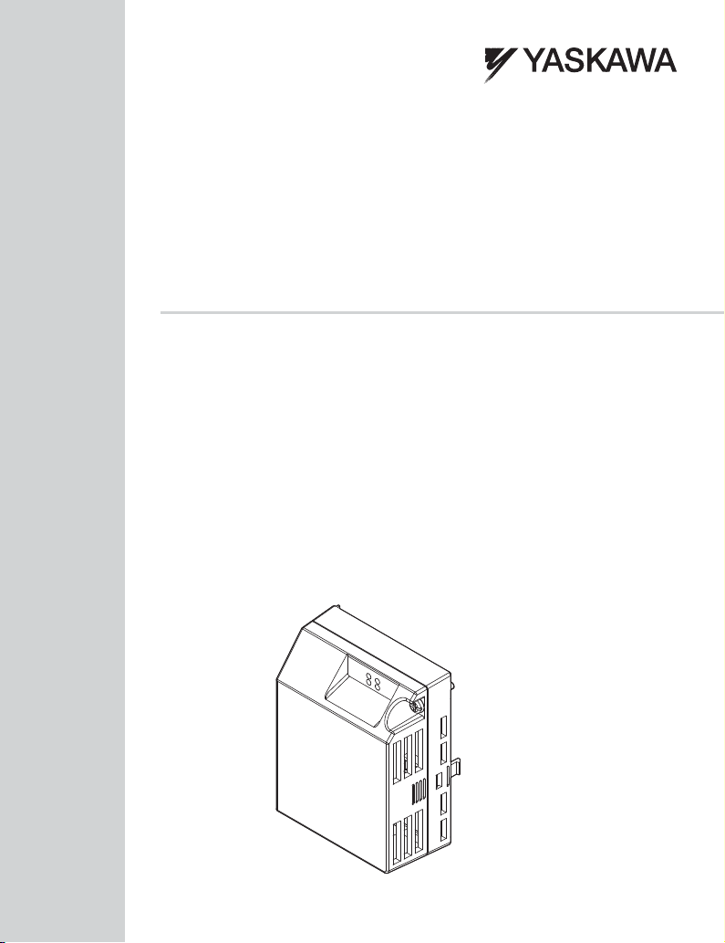
Option Unit
V1000 Option MECHATROLINK-II Installation Manual (this book)
Manual No. : TOBPC73060049
Read this manual first.
The installation manual is packaged with the MECHATROLINK-II Option and
contains a basic overview of wiring, settings, functions, and fault diagnoses.
V1000 Option MECHATROLINK-II Technical Manual
Manual No. : SIEPC73060049
The technical manual contains detailed information and command registers.
To obtain the technical manual access the site below:
http://www.e-mechatronics.com
Yaskawa Drive
V1000 Series AC Drive Technical Manual
This manual describes installation, wiring, operation procedures, functions,
troubleshooting, maintenance, and inspections to perform before operation.
To obtain instruction manuals for Yaskawa products access the site below:
http//www.e-mechatronics.com
V1000 Series AC Drive Quick Start Guide
This guide is packaged together with the product. It contains basic information
required to install and wire the drive. This guide provides basic programming and
simple set-up and adjustment.
Drive: Yaskawa AC Drive-V1000 Series
MECHATROLINK-II Option: Yaskawa AC Drive-V1000 Option MECHATROLINK-II
≥1016: Indicates a drive feature or function that is only available in drive software version
1016 or later.
RUN
ERR
TX
RX
STOP
(Hz)
(Hz)
(A)
(V)
Freq Reference
FWD / REV Sel
Output Freq
Output Current
Selected Monitor
Monitor
Verify
SetUpGuide
Parameter Set
Auto-Tuning
V1000
:
:
:
:
:
:
:
:
:
:
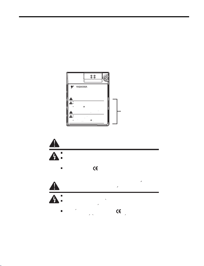
Risque de décharge
électrique.
Lire le manuel avant l'installation.
Attendre 5 minutes après la coupure de l'alimentation,
pour permettre la décharge des condensateurs.
Pour répondre aux exigences , s assurer que le
neutre soit relié à la terre, pour la série 400V.
Read manual before installing.
Wait 5 minutes for capacitor discharge after
disconnecting power supply.
To conform to requirements, make sure
to ground the supply neutral for 400V class.
Risk of electric shock.
WARNING
AVERTISSEMENT